To avoid these ads, REGISTER NOW!

Hoist Braking issue

paddymalta

New member
Joined
Sep 25, 2019
Messages
4
Location
MALTA Europe
Hi,
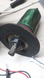
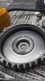
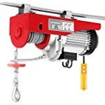
Can anyone know how the brake shown in the picture works? The brake is part of a Hoist which is not working , seems to be stuck when pressing the up or down buttons.
 

Attachments

  • 20190924_172443.jpg
    20190924_172443.jpg
    47.9 KB · Views: 36
  • 20190924_172445.jpg
    20190924_172445.jpg
    50.3 KB · Views: 36
  • 20190924_172451.jpg
    20190924_172451.jpg
    53.7 KB · Views: 33
  • 20190924_172455.jpg
    20190924_172455.jpg
    93.1 KB · Views: 34
  • 712QqPhFWtL._AC_SX679_.jpg
    712QqPhFWtL._AC_SX679_.jpg
    59.4 KB · Views: 39
  • 51vXlh2mNtL._AC_SR160,160_.jpg
    51vXlh2mNtL._AC_SR160,160_.jpg
    6 KB · Views: 140
To avoid these ads, REGISTER NOW!

RPH

Well-known member
Joined
Dec 17, 2006
Messages
4,190
Location
Michigan Thumb
Most brakes I have seen on hoists are deadman brakes. If it’s not releasing then make sure that current is flowing in the brake windings. No power to windings, no release.
 
OP
P

paddymalta

New member
Joined
Sep 25, 2019
Messages
4
Location
MALTA Europe
Most brakes I have seen on hoists are deadman brakes. If it’s not releasing then make sure that current is flowing in the brake windings. No power to windings, no release.

But as shown in the pictures the brake does not have any winding ... It is just connected to the motor rotor.
 

OccupantRJ

Well-known member
Joined
May 15, 2009
Messages
11,555
Location
Eastern North Carolina
The rotor core segments looks like an electromagnet. Does the clutch plate slide freely on the shaft so it can be drawn away from the friction area when energized? It may be spring loaded to clamp the friction area when de-energized.
 

Fasthotrod

Well-known member
Joined
Dec 14, 2015
Messages
218
Location
Oklahoma
I could be mistaken, but the one end of that rotor that goes into the front cover looks to have a helical gear on it. (Opposite of the brake.) Can you post a picture of the inside of the front cover? Does it have a spring in there that applies pressure to the motor/rotor assembly that pushes it back towards the back cover?

If I had to guess, the rotor is supposed to be able to move laterally along the length of the shaft so that when you apply power to the motor, the rotor assembly moves and disengages the brake from the back cover. When power is turned off, the assembly moves back towards the back cover and engages the brake disk against the back over, engaging the brake.

But I really have no idea... I'm just guessing by what I see in the pics.

Mark
 
To avoid these ads, REGISTER NOW!

walta

Well-known member
Joined
Jan 13, 2017
Messages
2,322
Location
Dutzow Missouri
Wild guess the motor armature is spring loaded so when no power is applied to the motor the spring pushes the in the direction of the blue arrow pressing the brake into a matting surface stopping the rotor. When power is applied the rotor is pulled toward the stator and then begins spinning.

I have seen this system on 1/32 HP gear motors buy no reason it would not scale up.


Walta
 

Attachments

  • 8.jpg
    8.jpg
    78.2 KB · Views: 14
OP
P

paddymalta

New member
Joined
Sep 25, 2019
Messages
4
Location
MALTA Europe
Update -

The Rotor has an internal Spring which the brake moves to the rotor as show in the picture attached. I have reassembled the motor, and cleaned the contacts of the up/down switch,but without success, it seams that the brake is moving but not strong enough to disengage and let the rotor turn free. I have bypassed the up/down switch so this will eliminate any doubt that current is passing full and check that the capacitor is good. Made another test but without any result, the motor still not turning .

The Stator winding has the same resistance 4 ohm

Note ; the gearbox is just a set of gears, no springs ecc ..

Any other suggestions ? thanks
 

Attachments

  • Rotor.jpg
    Rotor.jpg
    120.7 KB · Views: 21
  • Switch (1).jpg
    Switch (1).jpg
    144 KB · Views: 14
  • Switch (2).jpg
    Switch (2).jpg
    80.1 KB · Views: 16

walta

Well-known member
Joined
Jan 13, 2017
Messages
2,322
Location
Dutzow Missouri
It seems to me you would need 2 stator winding to change rotation. Winding A gets the full 120V and winding B get the cap in series with the winding for clock wise rotation, for CCW winding A gets the cap and B does not.

Is one of the winding open?

When the motor is not turning it should pull a lot of current 10 maybe 15 amps, you need that to pull in the brake. You are testing this at a good outlet not at the end of a long 16 gage extension cord correct?

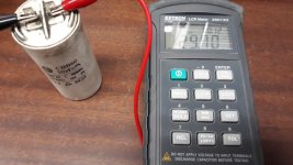
How did you test the cap?

Walta
 
OP
P

paddymalta

New member
Joined
Sep 25, 2019
Messages
4
Location
MALTA Europe
It seems to me you would need 2 stator winding to change rotation. Winding A gets the full 120V and winding B get the cap in series with the winding for clock wise rotation, for CCW winding A gets the cap and B does not.

Is one of the winding open?

When the motor is not turning it should pull a lot of current 10 maybe 15 amps, you need that to pull in the brake. You are testing this at a good outlet not at the end of a long 16 gage extension cord correct?

How did you test the cap?

Walta


Is one of the winding open?
No Each winding has 4 ohnms

When the motor is not turning it should pull a lot of current 10 maybe 15 amps, you need that to pull in the brake. You are testing this at a good outlet not at the end of a long 16 gage extension cord correct?
I will check the current.
Outlet is good.


How did you test the cap?
Old School - short it out with a screw driver and with an Lcr Meter .
 

Attachments

  • Winding (1).jpg
    Winding (1).jpg
    50.5 KB · Views: 8
  • wiring.jpg
    wiring.jpg
    43.4 KB · Views: 13
  • Winding (2).jpg
    Winding (2).jpg
    119.2 KB · Views: 9
To avoid these ads, REGISTER NOW!
Top Bottom