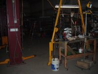
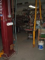
hello garage journal. I'm entertaining the idea of attaching a boom to the side of my 8000lb two post lift cable over top auto lift. This is just an idea I'm clearly not an engineer or i would not be on a forum asking about this idea. This boom would be a frame design and around 10-12ft in length attached with the lowest point being around seven feet off of the ground. It would be used for pulling engines from my race car. They weigh right around 500# . The picks would take place in the adjacent bay with the boom in line or less than 30 degrees from the axis of the two post . I have a general understanding of a free standing jib crane and the associated forces involved in that scenario. I know enough to build the boom frame and connection points to the lift post. I don't know how to figure the loads on the post or how they would or wouldn't transfer between the lift post. This is an idea not something im set on doing so please only constructive or informative replies.i don't need to be told I'm in over my head and I'm gonna kill myself. If you think that and you know what you are talking about please inform me of your reasons. Thanks in advance


You are using an out of date browser. It may not display this or other websites correctly.
You should upgrade or use an alternative browser.
You should upgrade or use an alternative browser.
Hoist/ crane
- Thread starter Jking24
- Start date
rockettgpw
Well-known member
I wouldn't be keen on mounting to a car lift but really don't know the pros and cons but I have built a jib crane that bolted to a 8x3 c section post in my shed frame. I made it so the vertical of the crane sat in a thrust bearing in a plate on the slab next to the post, thinking this set up would reduce the load on the post and there would just be tipping forces to worry about. The horizontal was about 9' long.
It didn't take much load to hear the shed post twisting and oil can noises from the steel cladding, not to destruction but it was clear a stiffer post would have been good.
Probably the heaviest thing I lifted was about 5-600lb, would be confidant to do a V8 engine swap with it.
It didn't take much load to hear the shed post twisting and oil can noises from the steel cladding, not to destruction but it was clear a stiffer post would have been good.
Probably the heaviest thing I lifted was about 5-600lb, would be confidant to do a V8 engine swap with it.
cvairwerks
Well-known member
The columns are not designed for that kind of load, and by the time you have the engineering done and the necessary reinforcements installed, you could have bought a gantry and been done. 500 lbs at 12 feet, with the boom structure, has a moment arm in excess of 6000 lbs....Add in it being a dynamic load and the numbers are even larger.
Last edited:
matt_i
Well-known member
Three things I think are important...
One is the deflection of the load beam, I think it should be something like an S8 or better for a 1/4t x 12' stickout...happen to be putting that size in my shop currently....you can consult jib crane catalogs for sizing the beam for 12' arm.
Two is the connections to the columns, especially the "back" column experiencing the uplift. Assume with steelwork and machine work, you have this part OK.
Three are the connections to the concrete. If a lift installed with common wedge anchors, I would remove them on the "back" column. The 500# on the end has to have a safety factor and be multiplied by the "lever action" of columns I am going to guess are 8ft apart. Could be up to 1 ton of uplift and nobody is allowed to install a jib crane (a machine built on reliability of the uplift connections) with a wedge anchor. They are built from as-cast anchor bolts or epoxied connections. Typically a jib crane can't be installed with epoxy anchors with a concrete depth less than 6" but the forces are also a lot higher.
For example, in the crane I'm installing its a 24" round base vs the ~96" base I envision in your setup. Easy to expect 6000# of uplift in my setup whereas yours should be 2000# or less.
If you did happen to drill-thru the slab when installing the wedges, it would be easy to hammer them thru, clean clean clean the holes with brushing and blowing compressed air from a metal pipette, and use Grade B7 threaded rod (mCMaster Carr, possibly Fasten-All). 24 hour cure on the epoxy before final torque at 68F so you might have to allow one more day if your shop is more in the 50F range. I like Sika AnchorFix2 which one can buy at Home D around here. Hilti also makes excellent products.
I would keep the overhead beam aligned with the set of columns as much as possible. To get the 30 deg of freedom I'm envisioning a pinned + rolling setup (sliding possible but more difficult to move) and a structure that could handle the load on the arc without deflection. It does put some misaligned load into the "front" column" but keeping it to 6" or 8" of centerline would seem very reasonable with the existing setup.
Last edited:
I will be doing all work and have all the material. So it's labor only and a gantry or bridge crane or anything else of the sort is out of the question. The lift post are already tied together and reinforcing them or even adding a removable tie bar or cable to help distribute the load would not be a problem. The foot print of the lift is just under 12ft center to center.The columns are not designed for that kind of load, and by the time you have the engineering done and the necessary reinforcements installed, you could have bought a gantry and been done. 500 lbs at 12 feet, with the boom structure, has a moment arm in excess of 6000 lbs....
thanks for the info. The 500# number is already on the conservative side engines are probably 10-15%lighter than that. The lift post are nearly 12' apart. Lessening the angle and keeping it dead in line is doable and if it's the only safe way it would probably lessen the boom to around 10' i was not gonna use a beam. But instead a aframe with a single attachment point for rigging. The lift is in the process of being moved from the old shop to the new so anchoring can be done however is appropriate. I believe we have that epoxy at my work. The slab is 5+inches #3 rebar 16 on center. And it will be pinned so that when it's not in use it can be swung 90° for storageThree things I think are important...
One is the deflection of the load beam, I think it should be something like an S8 or better for a 1/4t x 12' stickout...happen to be putting that size in my shop currently....you can consult jib crane catalogs for sizing the beam for 12' arm.
Two is the connections to the columns, especially the "back" column experiencing the uplift. Assume with steelwork and machine work, you have this part OK.
Three are the connections to the concrete. If a lift installed with common wedge anchors, I would remove them on the "back" column. The 500# on the end has to have a safety factor and be multiplied by the "lever action" of columns I am going to guess are 8ft apart. Could be up to 1 ton of uplift and nobody is allowed to install a jib crane (a machine built on reliability of the uplift connections) with a wedge anchor. They are built from as-cast anchor bolts or epoxied connections. Typically a jib crane can't be installed with epoxy anchors with a concrete depth less than 6" but the forces are also a lot higher.
For example, in the crane I'm installing its a 24" round base vs the ~96" base I envision in your setup. Easy to expect 6000# of uplift in my setup whereas yours should be 2000# or less.
If you did happen to drill-thru the slab when installing the wedges, it would be easy to hammer them thru, clean clean clean the holes with brushing and blowing compressed air from a metal pipette, and use Grade B7 threaded rod (mCMaster Carr, possibly Fasten-All). 24 hour cure on the epoxy before final torque at 68F so you might have to allow one more day if your shop is more in the 50F range. I like Sika AnchorFix2 which one can buy at Home D around here. Hilti also makes excellent products.
I would keep the overhead beam aligned with the set of columns as much as possible. To get the 30 deg of freedom I'm envisioning a pinned + rolling setup (sliding possible but more difficult to move) and a structure that could handle the load on the arc without deflection. It does put some misaligned load into the "front" column" but keeping it to 6" or 8" of centerline would seem very reasonable with the existing setup.
Innovate1
Well-known member
Not that familiar with lifts but the moment arm is big on this as others have pointed out. I may be missing something but why not just put the car/engine under the lift and attach the engine to the lift base (positioned above the car)? Load is centered and way under the limit of the lift. That ties up the lift bay but that's the only down side I see... Maybe the lift won't go high enough to make this work...
sberry
Banned
cvairwerks
Well-known member
You lift columns are not designed for the type of load that you want to impose on them. To get them to the capability you want, would require sheathing the entire column with additional steel, as well as digging up the foundation and installing new, much larger and significantly deeper piers.
Attaching a jib to a column significantly changes the side loading, as well as the ability for it to resist twisting along the vertical axis as well as the horizontal axis at the base.
Bridging over to the other column only changes the numbers a little bit, but now imparts loads on the second column that were not part of the original installation, and may interfere with the safety bar, if your lift has one.
I'd suggest taking the time to download and read one of the guides on jib crane design, and one of the analysis documents for real world design. Lastly, call your lift manufacturer and query their engineering staff on their thoughts, before you do something Darwin worthy.
Cougar
Well-known member
The columns are not designed for that kind of load, and by the time you have the engineering done and the necessary reinforcements installed, you could have bought a gantry and been done. 500 lbs at 12 feet, with the boom structure, has a moment arm in excess of 6000 lbs....Add in it being a dynamic load and the numbers are even larger.
X2.....
X2.....
Plus the anchors. In a lift with a car, its basically a balanced load, thus not too much tension on the bolts.
matt_i
Well-known member
I went back and re-read...and have to qualify my opinion above some.
What I had in mind is spanning both columns over the top and then the beam sticks out the side, Letter F pushed over on its side and so you have a total beam of around 20 ft. Forces are roughly as above.
BUT: if its trying to make one column do all of the work...then I would not do that. The open cross section "C" shape isn't conducive to that kind of loading nor is the reinforcement to the baseplate.
I went back and re-read...and have to qualify my opinion above some.
What I had in mind is spanning both columns over the top and then the beam sticks out the side, Letter F pushed over on its side and so you have a total beam of around 20 ft. Forces are roughly as above.
BUT: if its trying to make one column do all of the work...then I would not do that. The open cross section "C" shape isn't conducive to that kind of loading nor is the reinforcement to the baseplate.
I understand what your saying and really hadn't thought of that scenario. If it was that high the pivot would not be necessary a single beam would suffice I'll have to look at everything and see if that is a feasible option. I could possibly do somthing similar to one of the suggestions above like a gantry type setup with one side stationary but the span would need to be about 30' anyone have an idea of how big that beam would need to be ?
cvairwerks
Well-known member
If you are space limited, the easiest would be to set a jib with a movable outer support like sberry's, but make your outer support capable of moving down the beam or being removed.
JamesW84
Well-known member
Is there some reason why you can't use a engine/shop crane that can be broken down? I got one off Craigslist for a hundred bucks. It has the legs that go out under the load when in use, but you can stand them up and it would take up very little space.
https://www.oreillyauto.com/detail/b/acdelco-2734/tools---equipment-16488/shop-equipment-16634/lift-equipment-16815/engine-hoist-stand-18044/37ace89d5f92/acdelco-4000-lbs-engine-hoist/34786/2494215?q=Shop+crane&pos=2
https://www.oreillyauto.com/detail/b/acdelco-2734/tools---equipment-16488/shop-equipment-16634/lift-equipment-16815/engine-hoist-stand-18044/37ace89d5f92/acdelco-4000-lbs-engine-hoist/34786/2494215?q=Shop+crane&pos=2
Last edited:
Is there some reason why you can't use a engine/shop crane that can be broken down? I got one off Craigslist for a hundred bucks. It has the legs that go out under the load when in use, but you can stand them up and it would take up very little space.
Yes that's what we use now and have used for years but they are a pain because of the configuration of the car you have to come in from the side and that makes it harder to line things up. This would be much more practical
matt_i
Well-known member
This has got a pretty good chart about capacities of single bridge beams.
https://www.harringtonhoists.com/tech_support/edocs/EDOC 0367 rev02.pdf
https://www.harringtonhoists.com/tech_support/edocs/EDOC 0367 rev02.pdf
sberry
Banned
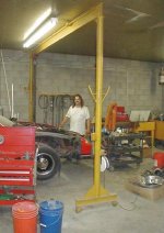
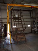
The one I show is only 1 way of doing it. I can see using a hoist post as one end of this design could design it as to almost go full circle. Reverse my design and bear one end on a post, would be a small load compared to a car. Wheels in an arc. The gussets a bit of overkill here but we had them.
Attachments
Last edited:
sberry
Banned
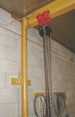
It makes it so strong, easy to over build it if a guy uses a 1/2 ton chain fall on it and this one is good for a ton. Gets past a bunch of fussy and expensive foundation, design, all of the problems.
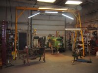
This was for a bud, I had thought about it but at the time an A frame was as practical and I can actually move it but did it once in 25 years when I built it. It had been in 2 buildings and thru a couple mods, upgrades. I custom cut the beam length for this, I really fussed with the geometry. The ergonomics are really good and used the end of the A for a tool station. Same equipment/tools used at the hoist and in the tractor bay.
This was for a bud, I had thought about it but at the time an A frame was as practical and I can actually move it but did it once in 25 years when I built it. It had been in 2 buildings and thru a couple mods, upgrades. I custom cut the beam length for this, I really fussed with the geometry. The ergonomics are really good and used the end of the A for a tool station. Same equipment/tools used at the hoist and in the tractor bay.
Attachments
Last edited:
The one I show is only 1 way of doing it. I can see using a hoist post as one end of this design could design it as to almost go full circle. Reverse my design and bear one end on a post, would be a small load compared to a car. Wheels in an arc. The gussets a bit of overkill here but we had them.
Yes i agree had a chance to take a long look at everything today and i think if i shift my lift towards the door about 1' i can build a 26' gantry setup using the lift post as one end and a rolling a frame on the other end it will cover the other two bays and probably 75% of my open floor space. This will be a safer more practical solution and i think it will be considerably less money and work
sberry
Banned
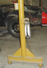
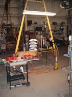
You could use an A frame on one end, I used a 1/4 wall pipe, won't bend with wheels on it.
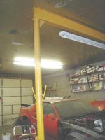
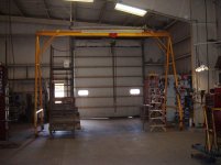
This is with my own. I have 19 ft, I fussed over it with limits, beam I had I took the crane out to work on it, paint,. At 19 could park the truck to the side, pick and trolly out sideways. I have a 2t chainfall. It was 2500# or so, all this wanted to do. 2 trollies would have been better and spread the load vs single point but it worked with care.
This is with my own. I have 19 ft, I fussed over it with limits, beam I had I took the crane out to work on it, paint,. At 19 could park the truck to the side, pick and trolly out sideways. I have a 2t chainfall. It was 2500# or so, all this wanted to do. 2 trollies would have been better and spread the load vs single point but it worked with care.
Attachments


Last edited:
so I'm gonna do swinging gantry setup pivoting off my lift post and a T post with wheels on the opposite end similar to sberry's wall mounted deal. I did a little digging around my yard at work and have acquired a beam to use i have referenced some of the lift company charts to get a idea of if it would fit my needs and I'm pretty sure it's about perfect. The beam is a w8x21 it will span a little under 26'. From the charts of I'm reading them correctly this beam is good for 2000# at 20' span. Is their any charts available or does anyone know a little more on the subject to figure the # it should be safe for at 26'.i couldn't imagine me using it for over 1000# but it would be nice to know a little more accurate number to avoid bending it should the need ever arise to lift more weight. Thanks again for all the help
matt_i
Well-known member
This is a good resource for sizing a beam.
https://www.harringtonhoists.com/tech_support/edocs/EDOC 0367 rev02.pdf
So they don't have your size. You should scale it by the Ixx values vs. those sections posted in my opinion.
For example Harrington specs a S10x25.4 for 25' span and 1 ton. The Ixx value you look up is 124 in^4 for that cross-section. For your beam W8x21 the Ixx value is 75.3 in^4.
So rating it for 1/2 ton would be acceptable in my estimation.
One of the more challenging tasks is to lift the ~550# beam up into the air so it can all be assembled.