What should the voltage meter read coming out of the LED Driver? I am getting just over 7 volts and the label on the driver says it should be .3 to 4 volts. Is this what I should be checking? I bought a replacement led chip (https://www.amazon.com/dp/B0B35TTSXX?tag=atomicindus08-20) but I am not sure that bulb Is bad, I read that it is more commonly the driver. I connected the multimeter probes directly to the outputs of the driver after disconnecting the bulb. Thanks for any help you can offer.

You are using an out of date browser. It may not display this or other websites correctly.
You should upgrade or use an alternative browser.
You should upgrade or use an alternative browser.
How do you test LED Drivers?
- Thread starter Tedison
- Start date

walta
Well-known member
Your LED driver is a constant current device. It will vary it output voltage in an effort to make 600 mA flow. 7 V unloaded sounds about right.
What is the voltage with the LED connected? More interesting is how much current is flowing.
The LEDs you linked to might work with that driver but you may need to put a jumper across the resister on the LED.
Walta
What is the voltage with the LED connected? More interesting is how much current is flowing.
The LEDs you linked to might work with that driver but you may need to put a jumper across the resister on the LED.
Walta
I agree.Your LED driver is a constant current device. It will vary it output voltage in an effort to make 600 mA flow. 7 V unloaded sounds about right.
What is the voltage with the LED connected? More interesting is how much current is flowing.
The LEDs you linked to might work with that driver but you may need to put a jumper across the resister on the LED.
Walta
Two additional notes:
1. The driver is rated at 600 mA and the LED is 700 mA. The LED may not reach full brightness in the best case.
2. The LED may require heat sinking to run indefinitely.
It looks like the driver is fully encapsulated in plastic. Which is good as it will almost certainly not have a transformer inside and you would be exposed to the full line voltage.
sounds like I bought the wrong LED replacement bulb.I agree.
Two additional notes:
1. The driver is rated at 600 mA and the LED is 700 mA. The LED may not reach full brightness in the best case.
2. The LED may require heat sinking to run indefinitely.
It looks like the driver is fully encapsulated in plastic. Which is good as it will almost certainly not have a transformer inside and you would be exposed to the full line voltage.
I should note that I will only be using 1 LED chip - even though I bought a 5 pack as this is an attempt to repair a small reading light. I know they are cheap but it is a good learning experience to fix this.What should the voltage meter read coming out of the LED Driver? I am getting just over 7 volts and the label on the driver says it should be .3 to 4 volts. Is this what I should be checking? I bought a replacement led chip (https://www.amazon.com/dp/B0B35TTSXX?tag=atomicindus08-20) but I am not sure that bulb Is bad, I read that it is more commonly the driver. I connected the multimeter probes directly to the outputs of the driver after disconnecting the bulb. Thanks for any help you can offer.
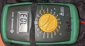
From the replies, it seems that I need to also test the mA output of the driver and if so I believe with a multimeter like the one I pictured, I need to be inline and have load going through the multimeter - can anyone explain how to do this or point me to a good video or other educational site? I have sites that reference being in line but they don't explain this very well.
American Locomotive
Well-known member
Your multimeter is unfortunately not capable of measuring the maximum current that driver can put out. It looks like only 200mA max according to the dial.
As mentioned, the way the drivers work is they try to maintain their rated current - in this case 600mA. The dataplate is saying that in normal operation, when it's outputting 600mA, the voltage will be around 3-4v.
As another person mentioned, those LEDs aren't really right for your driver. They have a built in resistor and are meant to be directly across 5v.
I think you are fine. just go for it, worse case you blew one LED or burn the driver. unless you do something really out of the ordinary.
. its a 700ma LED, 600ma will drive it at ? 85%? which is fine for LED. live longer as well... but can't say anything about the driver since its running 100%.")
2R4 is --> 2.4Ω
. its a 700ma LED, 600ma will drive it at ? 85%? which is fine for LED. live longer as well... but can't say anything about the driver since its running 100%.
resistor on led are always inline acting as current limiting. want a video here is the video... if you are into these things... just google up current limiting resistor, OHMs law, KVL, KCL and have your mind entertained.I have sites that reference being in line but they don't explain this very well.
2R4 is --> 2.4Ω
It's close on current ratings, and at this point I'd try it and see.sounds like I bought the wrong LED replacement bulb.
Edited to add: As @walta noted you'll want to short out that resistor as well.
walta
Well-known member
If the power supply is working correctly, it will never allow more than 600mA to flow thru the LED with or without the resistor. The LEDs have an on-board resistor to flow the correct current when 5 volts is applied. When using the constant current power supply the resistors presents will raise the power supplies output voltage but the current thru the LEDs and the voltage across the LEDs should be unaffected. The resistor will make some heat is the only down side to leaving it in the circuit.do not short out the resistor inline.
Walta
I am not sure what current limiting vs voltage dropping means. 3.7v is a typical forward voltage of diodes. Or what current limiting does. If it was me, I would just leave that resistor on the chip even if the driver is current mode or not.If the power supply is working correctly, it will never allow more than 600mA to flow thru the LED with or without the resistor. The LEDs have an on-board resistor to flow the correct current when 5 volts is applied. When using the constant current power supply the resistors presents will raise the power supplies output voltage but the current thru the LEDs and the voltage across the LEDs should be unaffected. The resistor will make some heat is the only down side to leaving it in the circuit.
Walta
American Locomotive
Well-known member
The LED driver has an upper voltage limit. It will attempt to drive 600mA through that LED, even with the resistor in place. That may cause the driver's output voltage to go beyond its design threshold.I am not sure what current limiting vs voltage dropping means. 3.7v is a typical forward voltage of diodes. Or what current limiting does. If it was me, I would just leave that resistor on the chip even if the driver is current mode or not.
Ok…The LED driver has an upper voltage limit. It will attempt to drive 600mA through that LED, even with the resistor in place. That may cause the driver's output voltage to go beyond its design threshold.
I am waiting for that science challenged guy from the other thread to chime in…
walta
Well-known member
The label on the drivers says the max voltage is 4 Volts at 600mA but the OP has measured 7 volts at zero amps. Maybe it will work with the resister but maybe not.
I never saw an answer to this question I asked in post #2 “What is the voltage with the LED connected?”
We might as well let this thread die as the OP has not be back to this sight for 3 days now.
Walta
I never saw an answer to this question I asked in post #2 “What is the voltage with the LED connected?”
We might as well let this thread die as the OP has not be back to this sight for 3 days now.
Walta
Hello - I have been meaning to update this thread with my results and finally have a chance to do so. In short, it worked. That is, I tested for continuity on the old led chip and it failed. I tested the new chip for continuity and it passed and lit up as I tested it. Soldered it in, applied some thermal paste to the back of it and my reading light is back in action. Now on to the next project - taking a floor reading/lamp that I stripped the non working fluorescent parts out of to make way for conversion to a dimmable LED light. Time to replay the videos from above and figure out whether I need constant voltage or current - I have 4 left over chips from the fix of the light in this thread. Thanks all for you help, if anyone has a reliable supplier for parts for led builds please share! Lots of inexpensive stuff on Amazon and AliExpress etc but who knows about the quality.
walta
Well-known member
The LEDs you bought were intended to work with a 5 volt DC power supply and I see no reason to reinvent the wheel. Almost an old USB phone charger should run your LEDs just fine.
Thanks for the update.
Walta
Thanks for the update.
Walta