To avoid these ads, REGISTER NOW!

How to choose a MOSFET

JackOfDiamonds

Well-known member
Joined
Jul 31, 2020
Messages
709
Location
Idaho (USA)
I don't do EE stuff enough to remember how to pick out the right MOSFET for a particular job. Plus when I go to a site like digikey, I get 48,945 options and can't tell any difference between them.

What I want to do is not fancy or high-speed. I could actually use an automotive relay, but I want to minimize the current draw, and figured a MOSFET would be better since they have very low / zero gate current.

I want to switch a 12V load, consisting of LED trailer lights, maybe 2-5 amps depending on the FET I can get. To switch it, I'm going to have pulsed 6-16V coming from a wheel dynamo. I will feed that into a capacitor to smooth it into DC and also act as a latch, so the MOSFET will stay switched on for a minute or so after the input stops pulsing, so the trailer lights stay on when I stop at a stoplight. That's the purpose of using a MOSFET; if I used a relay, I would need a pretty big capacitor because relay coils draw a few mA and the wheel dynamo might not actually keep it latched at all.

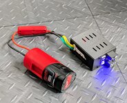
It needs to have radial leads so I can wire it up easy and other than that would something like this work?
 
To avoid these ads, REGISTER NOW!

LopezBart

Well-known member
Joined
Oct 13, 2023
Messages
2,577
Location
Lopez Island, WA
So this is on a bicycle, right? Self contained trailer lights that you want to shut off automatically? Powered from the wheel dynamo which charges a small battery?

You may wish to think about how the circuit will behave if you start w/ a dead battery. You may wish to think of this as a circuit that disconnects the battery from the connection after the pulses stop, and leave the dynamo always connected to the lights so it fails safe.
 
OP
J

JackOfDiamonds

Well-known member
Joined
Jul 31, 2020
Messages
709
Location
Idaho (USA)
The dynamo won't drive the lights or charge the battery. Not enough power. I love my dynamo; hate my dynamo lights. The idea is to get LED trailer lights from Harbor Freight, wire them to an M12 battery, and have the dynamo switch them on. But I still want to retain the normal lights on the bike, so the circuit has to not interfere with that.
 

Tactile

Well-known member
Joined
Sep 2, 2020
Messages
270
Location
Melbourne, AU
How about a solid state switch like the ones found here? This is an Australian site but I'm sure there will be something local to fit.
 

Innovate1

Well-known member
Joined
Jul 28, 2014
Messages
4,315
Location
Illinois near St. Louis, Missouri
I don't do EE stuff enough to remember how to pick out the right MOSFET for a particular job. Plus when I go to a site like digikey, I get 48,945 options and can't tell any difference between them.

What I want to do is not fancy or high-speed. I could actually use an automotive relay, but I want to minimize the current draw, and figured a MOSFET would be better since they have very low / zero gate current.

I want to switch a 12V load, consisting of LED trailer lights, maybe 2-5 amps depending on the FET I can get. To switch it, I'm going to have pulsed 6-16V coming from a wheel dynamo. I will feed that into a capacitor to smooth it into DC and also act as a latch, so the MOSFET will stay switched on for a minute or so after the input stops pulsing, so the trailer lights stay on when I stop at a stoplight. That's the purpose of using a MOSFET; if I used a relay, I would need a pretty big capacitor because relay coils draw a few mA and the wheel dynamo might not actually keep it latched at all.

It needs to have radial leads so I can wire it up easy and other than that would something like this work?

6V is a little low for typical MOSFETs. They do make some "logic level" ones that work on lower voltage and for the current you need to handle you should be able to find something. You don't need 200V devices - there are lots of 60V and lower parts and with lower voltage you can get higher current parts all other things being equal. As I recall bike generators put out AC so you could do a doubler rectifier to get higher voltage. I wouldn't just feed the FET with the filtered DC. The slow turn off will create heat in the device although at the low currents it might not be a problem. You could add a schmitt trigger or a comparator with positive feedback to get clean, fast turn on and off.
 
  • Like
Reactions: Max
OP
J

JackOfDiamonds

Well-known member
Joined
Jul 31, 2020
Messages
709
Location
Idaho (USA)
So I could feed the cap with the raw generator output. If I had another source of voltage like a VCC rail, which I don't, I could run that capacitor voltage into a comparator, and when it slowly rose up to the threshold, the comparotor would switch full Vcc to the MOSFET. But I don't have any VCC rail here with which to set up a comparator, unless I use my 12V as Vcc, which I guess would work.

For that matter, I could just use a comparator alone, then since some comparators can drive current, I don't even need a MOSFET anymore if my comparator can drive enough current for my lights.

I have some small 12V relays I could use instead of a MOSFET, which also wouldn't have any on resistance, but the coils are about 65 Ohms, which I calculate will waste about a half a Watt just keeping my relay on.
 
Last edited:

Innovate1

Well-known member
Joined
Jul 28, 2014
Messages
4,315
Location
Illinois near St. Louis, Missouri
Run the control that drives the MOSFET off the 12V supply. That's a good voltage for the gate. Just use the comparator to sense when to turn on. For sizing the MOSFET the main consideration will be heating rather than the data sheet current rating (that sometimes is at 25C which is totally unrealistic for most applications). If you aren't going to use an external heatsink then 1/2W loss would keep the part fairly cool. At 5A that would mean the resistance would need to be 20 milliohms. IRFZ44N has an on resistance of 17.5 milliohms at 25C which is about 1.8 times that at 100C but it shouldn't get that hot. That or a similar part should work ok for this. If you put this on a heatsink you can use a higher resistance part but these are cheap and lowering losses for battery power is always a good thing.
 
To avoid these ads, REGISTER NOW!

Max

ALLIANCE MEMBER
Joined
Jun 16, 2018
Messages
3,370
Location
Georgia
I don't do EE stuff enough to remember how to pick out the right MOSFET for a particular job. Plus when I go to a site like digikey, I get 48,945 options and can't tell any difference between them.

What I want to do is not fancy or high-speed. I could actually use an automotive relay, but I want to minimize the current draw, and figured a MOSFET would be better since they have very low / zero gate current.

I want to switch a 12V load, consisting of LED trailer lights, maybe 2-5 amps depending on the FET I can get. To switch it, I'm going to have pulsed 6-16V coming from a wheel dynamo. I will feed that into a capacitor to smooth it into DC and also act as a latch, so the MOSFET will stay switched on for a minute or so after the input stops pulsing, so the trailer lights stay on when I stop at a stoplight. That's the purpose of using a MOSFET; if I used a relay, I would need a pretty big capacitor because relay coils draw a few mA and the wheel dynamo might not actually keep it latched at all.

It needs to have radial leads so I can wire it up easy and other than that would something like this work?

I think that FET will work. Make sure that you heat sink it well. Rds on is .18 ohm, so at 4A you’ll be dropping less than a watt assuming that the dynamo is turning the FET fully on.

From your text, I expect that there is a battery feeding the LED lights that the FET will switch? And the cap is on the gate of the FET to smooth out the ”on” plus add some turn off delay?

I wonder about the Amazon part though. It’s some kind of copy or remark of an IR (International Rectifier) part, and I’ve got no idea how good “Bojack” is. I’d be worried about a cheap chinese part that doesn’t meet IR specs despite the reviews.
 

Max

ALLIANCE MEMBER
Joined
Jun 16, 2018
Messages
3,370
Location
Georgia
So I could feed the cap with the raw generator output. If I had another source of voltage like a VCC rail, which I don't, I could run that capacitor voltage into a comparator, and when it slowly rose up to the threshold, the comparotor would switch full Vcc to the MOSFET. But I don't have any VCC rail here with which to set up a comparator, unless I use my 12V as Vcc, which I guess would work.

For that matter, I could just use a comparator alone, then since some comparators can drive current, I don't even need a MOSFET anymore if my comparator can drive enough current for my lights.

I have some small 12V relays I could use instead of a MOSFET, which also wouldn't have any on resistance, but the coils are about 65 Ohms, which I calculate will waste about a half a Watt just keeping my relay on.
Never say never, but I’d be surprised if you could find a comparator that drives 4 Amps. Note that at 4A your FET is going to be dropping up to 2/3 of a watt.

I missed in my earlier answer that the generator provides only 6V. Use a doubler or comparator as @Innovate1 suggested. Note that you may have to adjust the gate cap size to get the delay that you want.
 

Innovate1

Well-known member
Joined
Jul 28, 2014
Messages
4,315
Location
Illinois near St. Louis, Missouri
I think that FET will work. Make sure that you heat sink it well. Rds on is .18 ohm, so at 4A you’ll be dropping less than a watt assuming that the dynamo is turning the FET fully on.

From your text, I expect that there is a battery feeding the LED lights that the FET will switch? And the cap is on the gate of the FET to smooth out the ”on” plus add some turn off delay?

I wonder about the Amazon part though. It’s some kind of copy or remark of an IR (International Rectifier) part, and I’ve got no idea how good “Bojack” is. I’d be worried about a cheap chinese part that doesn’t meet IR specs despite the reviews.
Better check your math. I squared x R for 0.18 ohms and 4 amps is 2.88 watts. It would work with a good heatsink but lower resistance parts aren't much more expensive and easy to find. Also, the resistance will be higher at operating temp so the power will be higher - probably about 30-50% higher.

BTW, IR is now part of Infineon. I agree with your suspicions that Bojack is likely a worse copy of the genuine part.
 
  • Like
Reactions: Max

Max

ALLIANCE MEMBER
Joined
Jun 16, 2018
Messages
3,370
Location
Georgia
Better check your math. I squared x R for 0.18 ohms and 4 amps is 2.88 watts. It would work with a good heatsink but lower resistance parts aren't much more expensive and easy to find. Also, the resistance will be higher at operating temp so the power will be higher - probably about 30-50% higher.

BTW, IR is now part of Infineon. I agree with your suspicions that Bojack is likely a worse copy of the genuine part.
Thanks for the catch - I was in too much of a hurry.
 

iron block

Well-known member
Joined
Jun 22, 2015
Messages
265
Location
Bay Area, CA
I want to switch a 12V load, consisting of LED trailer lights, maybe 2-5 amps depending on the FET I can get.

Just to confirm -- your LED trailer lights are turned on by pulling their negative lead to ground, right? Because if they need +12 applied to their positive lead to turn on, then you need a different kind of MOSFET/driver circuit. Just checking...
 
OP
J

JackOfDiamonds

Well-known member
Joined
Jul 31, 2020
Messages
709
Location
Idaho (USA)
Either kind of switch will work just as well (switching the hot or switching the ground).

My current plan is to use one of these modules that have a comparator driving a real automotive relay. The interface to the dynamo is then the comparator, which has very high input impedence so there won't be any load on the dynamo, plus adjustable voltage comparison threshold. And the output interface to the lights would be a normal 10A automotive relay.


The benefit of using a relay is no voltage drop, so I could also change course and use it to switch 5V USB if I want to, instead of 12V, if that turns out to be better (there are a lot of bicycle lights and stuff that run off USB-C nowadays). The power to drive the relay coil can come from the output circuit (M12 battery).

What remains to be tested is if adding a cap and diode to the front of this comparator module will have the desired operation of turning it on when the bike is in motion and leaving it on for a period of time afterward. Since the voltage from the dynamo could spike up higher than 12V, and definitely higher than 5V, I don't know if that's a problem for the comparator. I could put a zener diode across the input to clamp voltage spikes but I don't know if it's really needed.
 

Innovate1

Well-known member
Joined
Jul 28, 2014
Messages
4,315
Location
Illinois near St. Louis, Missouri
Just to confirm -- your LED trailer lights are turned on by pulling their negative lead to ground, right? Because if they need +12 applied to their positive lead to turn on, then you need a different kind of MOSFET/driver circuit. Just checking...
Good question! Most trailer lights switch the positive lead which would need a P channel MOSFET or a gate drive of about 24V (12V above the 12V supply. Not a huge issue but makes things slightly more complicated. And P channel devices are somewhat less common but still widely available. And the physics of the devices make the P channel parts have higher on resistance all other things being equal.

This sounds like a custom bike trailer so it could probably be set up to switch the negative lead with N channel parts.
 

LopezBart

Well-known member
Joined
Oct 13, 2023
Messages
2,577
Location
Lopez Island, WA
Since the voltage from the dynamo could spike up higher than 12V, and definitely higher than 5V, I don't know if that's a problem for the comparator. I could put a zener diode across the input to clamp voltage spikes but I don't know if it's really needed.
I would definitely condition the output of the dynamo; if for some reason the wire to the LED light comes loose, you'll have significant voltage spikes. It's easy enough as you note; add some resistance before the Zener of course...
 
OP
J

JackOfDiamonds

Well-known member
Joined
Jul 31, 2020
Messages
709
Location
Idaho (USA)
This is what I came up with. One of the comparator/relay boards works perfectly with just a doide and a cap on the input to make an adjustable delay circuit. It switches on with the slightest motion of the dynamo wheel and I have it adjusted to stay on about 3 mm minutes. It only draws about 20 microamps from the aux battery on standby.

To protect the batteries, I added a second comparator board in series as a low-voltage dropout. Both boards can be bypassed independently.

It should work with practically any batteries but I plan to use M12 batteries. Couldn't resist putting a USB charging port on while I was at.
 

Attachments

  • PXL_20241211_003121496~2.jpg
    PXL_20241211_003121496~2.jpg
    576.1 KB · Views: 16
To avoid these ads, REGISTER NOW!
Top Bottom