
To avoid these ads, REGISTER NOW!

How To Trick Your Athol Vise

steelkilt

Well-known member
Joined
Oct 28, 2011
Messages
56
user100140_pic45481_1417395073_zpssmt8ewjy.jpg

How to trick your Athol! Many of you know that I'm a big fan of utilizing the "spinner" handle function Parker incorporated on their later vises, (you know how you wondered what that threaded hole in the yoke was for!) so I decided to borrow that feature and incorporate it into these two Athols as well as a myriad of other upgrades that have been bouncing around my brain for a bunch of years! The work performed here will be on my two nearly identical Athol 614 1/2's. These have the typical Athol buttress threads and bushing-spring-bushing garter system. That said, I'm going to replace that system with a friction-less bushing system to take full advantage of the "spinner function". I'm not very good at documenting these, so I may have missed a few pics but you should be ok. Here goes...
Now, you know how you hate that bend in the handle. Yes, you straightened it to perform just fine, but still.... and since your tricking this out, you might as well do it right by going all the way.
So, as long as YOUR Athol (or whatever brand you are doing this to) handle ends have the typical "swagged" ends, you can simply grind off the very end to get the handle end off.
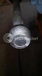
20140911_175819_zpsx5qxzhei.jpg

Otherwise, you'll need to cut depending on the manufacturer. I would grind the whole handle end off so you can still use the vise as well as get it repaired if things go bad, you never know...
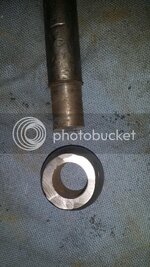
20140911_175930_zpsqqpmfoqy.jpg

The point is, you need to get the handle out of the yoke to be able to measure the hole diameter. I use sockets (yes, the ones that belong on a socket wrench) and a harbor freight vernier calipers. Why do you care about this step? Simply put, you are trying to remove the "bellying" that has developed to the yoke over the years from constant tightening and loosening. This action opens the outsides of the yoke more than the inside. Perhaps I'm not explaining very well but what we are trying to accomplish is getting a consistent hole diameter all the way thru the yoke to reduce back-and-forth handle flip-flip, essentially allowing the new handle to "slip" thru the yoke smoothly, that's all.
Now, I only have a drill and drill press so I had to increase drill bit diameters by 1/64" until I achieved the desired bore size for my new handle.

20140911_180050_zpszt2kuiif.jpg

WARNING, be very cautious NOT to overbore the hole. Keep in mind, when you are done with this step, it MUST look aesthetically pleasing! It may do you well to make a "mock up" using some turned down wood or something of very similar size into the handle hole and step back and make sure you are happy with it. If you must leave some "bellying" in the yoke, that's no big deal. I like the handle diameter to be about 2 or 3 thousandths smaller than the bore. WARNING... Keep in mind that you are going to need to have a groove in the middle of the new handle for the spring loaded ball bearing to pocket into. Mine are 5/32" Radius (not diameter!) Just keep this in mind for your handle specs.

January%201%202015%2084334%20AM%20PST_zps4dxhrd5l.png

Now, your handle ends. Much of this is subjective do to the difference in manufacture, so please be sure to think this thru because what I have done here to this vise does NOT apply to all vises. Here goes... there are more than two different profiles on screw-yokes out there but we are going to focus on these two: the ball-shaped and the cylinder-shaped screw-yoke. First, the cylinder shaped. While your welcome to pick whatever shape of handle end you want, you must keep in mind that the face that meets the yoke (the point at which you get your blood blisters from) will NOT interface quite correctly because of the two different profiles of the two parts. This seems to be best rectified by some good finger savers (I got mine from inspector house on eBay).
Next, the ball-shaped screw-yoke. These are the screw-yokes on the two Athols I'm discussing in this thread.
I truly loathe the interface relationship between the acorn-shaped handle ends and the screw-yoke on the L.S. Starretts because every time the handle slams down into the yoke, it acts like a driving wedge into the yoke (see pic of undeformed Athol). Thereby deforming the yoke into some kind of deburring nightmare!

ecember%2027%202014%2030539%20PM%20PST_zps3cdy7myb.png

As if that area wasn't dangerous enough. Much more to come.....


HOWEVER, the Starrett acorn ends are probably my favorite profile and would be TOTALLY at home on these two. (After all, Athols are the predecessors to Starrett) So I tried to get the best of both worlds, the updated acorn- shaped handle ends, but designed in such a way as to avoid deforming the screw-yokes. Here's what I came up with: I scaled up all the dimensions of the acorn handle end. This served three functions: first it better matched the new increased diameter handle so it pleased the eye and secondly, the heavier mass of the larger ends offered increased inertia for better spinning (more on that later). Lastly, the increased size allowed for the interior face to be increased so that any hard bumping is outboard of the edges of the eye yoke. So any contact is about in the red area.


Continued in next post...
 
Last edited:
To avoid these ads, REGISTER NOW!
OP
S

steelkilt

Well-known member
Joined
Oct 28, 2011
Messages
56


I measured the radius of the screw-yoke and transferred that dimension (actually I slightly decreased the radius on the end)to the interior face of the acorn handle end, thereby, eliminating any chance of "boogering" up the yoke because all contact is far outboard of the edges of the screw-yoke eye.

Now we turn our attention to the spring loaded ball bearing detent function. As you know, Athols do NOT come with threaded holes for this function to be utilized so....we incorporate it ourselves. Both my Athols already had dimples so centering the hole to be drilled was not much of an issue for me. You ask me "what size?" This will have to be your call. But keep in mind you will be tapping this hole and you'll need to obtain the largest ball bearing possible to fit inside this tapped hole. If your still concerned you'll have to consult with your machinist. Both of these Athols are 21/64" hole, 3/8-24 tap (and set screw), 5/16" ball bearing. Basically, the relationship between handle diameter and ball bearing diameter should please the eye and serve it's function properly. (Also, it should go without saying but all of this drilling is done with NO HANDLE IN IT) WARNING... use a drill press or any other machine that will allow you to drill this hole as straight and centered as possible! This is because the whole main screw is going to be spun later for polish....So drill straight! Now, tap the hole with the appropriate tap.


I included in the above picture the variety of different springs and length of set screws. Trips to a good hardware store is a necessity.
It seems best to work your way up by increasing drill bit diameters until you get to the appropriate size to run your tap.


Tap the thread all the way thru the yoke.


Now, this is the method I use to polish the yoke. Get the appropriate hardened steel bolt, make sure you get it threaded long enough to bottom out on the back side of the eye hole because you are going to be spinning it clockwise in a drill. Also make sure you have it long enough on the drive side to be chucked into a drill chuck. See pics. I use a piece of pvc pipe that (just) fits over the threaded part of the main screw and clamp the pvc horizontally in a vise to keep it stable....see pics...or whatever you want to use to keep it secure while spinning it. I hold sandpaper in one hand and run the drill with the other moving from 80 grit to 2000 grit. Give it a shot, this is not going to ruin anything on the yoke.


Continued....
 
Last edited:
OP
S

steelkilt

Well-known member
Joined
Oct 28, 2011
Messages
56


We now turn our attention to removing as much unnecessary friction as possible from the yoke/dynamic jaw relationship when closing the vise. "Why bother" you ask? Because you've hung in there and gone this far with that nice, shiny new handle and that mirror finished yoke, it's only a couple bucks more to complete your task in "Bristol fashion"!

The quickest way I thought of to remove the cotter pin from being under tension is to file a groove into a piece of pvc (slightly larger than the cotter pin diameter) with the side shoulder if a large file.

I recommend using the same piece of pvc that you utilized on the last step in allowing the main screw to spin inside of it to shine the yoke, remember? However, this piece has to be long enough to slip inside the dynamic jaw as well as over the main screw.


Now all you have to do is straighten the cotter pins legs (it's best to rock them back and forth to break them off for two reasons : First, it takes away any chance of gouging the inside of the dynamic jaw when you inevitably have to spin it 180° anyway to fully remove the pin. And second, when you do rotate the main screw it will be easier to remove because you won't be able to straighten the legs on the underside because you HAD JUST ROTATED THE SCREW to get to the "head" of the cotter pin. It's a vicious cycle, just break the legs off...). You are NOT re-using the cotter pin again, you are entering into some tighter-tolerance, finer workmanship here. You'll be most pleased that you spent the extra $2 for a package if 5. Now, disassemble to remove the two bushings and the spring.


I wouldn't throw it away or anything because you never know if the next vise owner might want it and I'm always more comfortable with being able to return everything to OEM standards. But that's just me, if you really want to, chuck um'!

My original intent was to introduce a very thin thrust bearing to install between the yoke and dynamic jaw, like some have done to our "split nut" Reeds. But there isn't a whole lot of room in these Athols to get a tb in there without making an ugly mess so I decided on the next best thing, to have a super slippery washer made out of some high-end bronze aluminum (More on these sources later). I had mine made to about half of the thickness of the "shelf" (.080") because I wanted to make sure there was plenty of "shelf" left after installing the washer for the yoke to index itself.


Otherwise, the main screw could ride on the interior edge of the washer bore instead of the shelf, particularly as the vise loosens up.


Your results will most certainly vary, but make sure to take this into consideration. DON'T let my thoughts deter you from a better solution. Your capabilities and resources probably far exceed mine, I'm just trying to utilize what's available to me while recognizing my tool limitations. But, I'm sure there is somebody out there that can incorporate a "better mouse trap" than me. By all means, I'd be very pleased to see a tb incorporated some how!

Please plan well here before any assembly. Consider the thickness of the new washer and bushing, as well as the correct size cotter pin (mine was somewhat uncommon). Your goal is to have very, very little "play" in there so as to insure a smooth, tight open and close action. Yes, yes we ALL dislike turning the handle and not seeing the jaw move! While we know that there are some vises out there that seem to have that play no matter what you do to take it out, they are the exception, not the rule. These Athols definitely fall into the "well made category", especially when the main nut is captivated correctly (more on THAT in a later step...). A note here: I was going to install a "wave washer" at this stage between the long bushing and wall of the dj to remove any slack from that area but I figured I would forego it for now because I could always utilize it later if I wanted. That said, I'm glad I didn't because the action is terrific without it.

For me, this assembly was the last area that I assembled before assembling the handle and ends but you may be different. I mock assembled the new washer and bushing several times. Then little by little ground down the bushing on my bench top grinder until I could BARELY sneak the cotter pin into the hole. After a couple three tries it slipped in great! I'm confident this will go fine for you, should you decide to go this route.


Sorry about the above picture, but if you look closely you can see the approximately 1" long bushing.

This completes the work I performed on the garter and yoke/handle/ends of these vises. I intend to move on to some other areas like illustrating how to eliminating the gaps when closing the jaws and improving the alignment between the main nut and screw and a few other "trick" items.

But let me say a few things about some of the folks that helped me out with these two vises (as well as a few other vises).

First up is my buddy Ritzblitz on this forum. Without his tenacity on returning emails and my constant badgering him with hair-brain, outlandish, over-the-top, and just plain silly ideas to incorporate on a couple pieces of old cast iron. Without his great attitude and desire to help me out, these beautifully machined bits would never have come to fruition. I can tell you this, if you saw and touched these handles, you'd want new ones on your vise. I, for one appreciate the fact that he helps us out on the "vises" thread.

Next up is KMScott, who also doesn't need any props. Nothing (and I mean nothing) has EVER come out of his shop "ok" or "good enough"! It won't happen. Go ahead and punch in his name under the search box and salivate while looking at his wares. He also makes time for us on the thread even though he's way busy with making more money elsewhere. Notice that beautiful flat washer with it's lubrication "troughs", I mean, how pretty can a washer be? ! ! If you need jaws for your vise, he's definitely the go to guy.

So go ahead and order some new pieces for your pincher! They're quite wonderful to behold in your hand. And no, I don't get anything from these folks for saying so...I'm just very appreciative. Now back to our program.....
 
Last edited:
OP
S

steelkilt

Well-known member
Joined
Oct 28, 2011
Messages
56
This now brings us to another area of the vise, the relationship between the main screw and the main nut.

You may ask, "Why would we want to bother messing around with this area? What is to be gained in fooling around here?" Simply put... much. I'll explain a little here. If you hadn't noticed, manufacturers only machine a few critical areas of the casts, leaving the rest of the parts in the casted state. I'm sure you don't need to be told each vise varies ever so slightly from each other. Sometimes there are large dis-similarities, sometimes they are nearly replicas. I'll let someone else who knows explain why this is, because I could only speculate. But what we are concerned with here is improving the relationship between the main screw/nut by first, assessing if/where improvement needs to be done, and how? Our desire is to have the screw/nut relationship, "true". Maybe it's best to think of it as sighting in a gun. That is, we want it co-planer, even left/right and up/down, in consistent relationship with the dynamic jaw through its full in/out range. As well as directly in line with itself ( the screw/nut should not be kinked left, right, up, down). I know this sounds like allot but all we're really going to do is shim certain areas to manipulate the screw/nut into proper alignment, that's all. I'm sorry to get long winded here but I'm limited on what I can do with pictures.

Now, that said, the manufacturers vary GREATLY on this. Your particular vise of manufacture may not need improvement here, or not even be designed as such ( Wilton bullets are incorporated with "tolerance" built into the design so there would be no need to try to benefit from this step on a bullet, only sliding dovetailed nut vises). These Athol's have very "loose" tolerances in the sliding dovetail pocket (where the main nut is located). But they make up for it in strength, this area is truly overbuilt in Athols.

It will take some very close attention and study of this picture to understand what's going on here. I apologize for this, simply put, its very difficult to get a 3D understanding of a 2D picture. These Athols have a "bolstered lip" on all the critical contact point areas of the sliding dovetail pocket (as represented by the red arrows)....except in two areas( the blue arrows).


I suspect the reason Athol didn't incorporate this lip on these two areas is because when the vise is in action, these areas are receiving more of a thrust load than anything else. But this I know for sure, it changes the shim dimensions considerably, making it more time consuming.

Our goal is to encapsulate the nut (by shimming it) in one or both of the "walls" and/or the "floor" of the sliding dovetail to isolate it in proper relationship with the main screw while maintaining that relationship through the dj's full range.


The advantage here is having the main screw in perfect alignment with the main nut, this in turn will always keep the threads appropriately engaged around the main screw, thereby, at least theoretically, we can expect the screw/nut to always be in its "strongest, threads fully engaged, position".


You may ask, "how do I know if the nut is in proper alignment with the screw"? I first try to look for a few tell-tale signs that immediately alert me to an issue. The first, and probably the most obvious, is binding. As the dj goes in and out, the screw/nut relationship changes, this will typically cause you to need to apply more pressure at either of the two extremes ( this was the case with both of these vises, however, one would bind in the almost closed position, the other, in the almost fully open position....go figure! ). So try to pay very close attention to the action through out the whole range. Incidentally, hence the name of the thread, if you are shimming a similar Athol, both of their main nuts needed to be shimmed at both "top walls", with no shimming on the forward floor (although the rear floor did get a thin shim for final tweaking). Next, I measure both the front and the rear part of the top of the nut to the interior upper edge of the vise to make sure it's consistent both front to rear. This immediately reveals any misalignment. Next, we remove the dj from the main screw and thread it a couple inches into the nut and try our best to eyeball correct alignment up/down and left/right. It seems like this is difficult, but really, much of these are a few minutes each step with the exception of obtaining the appropriate shim thickness material. At least it was for me.
I know that seems like allot but I'm just trying to be as thorough as I can. It really isn't difficult, albeit a little time consuming, and its quite cheap (maybe even free) but boy-o-boy will this step make a SILKY SMOOTH action when you do a good job. Trust me, I wouldn't have bothered with this step on my second Athol if I hadn't already learned the full benefit of what it did for the first! It truly is a necessity for these models of Athols and most of the other manufacturers!

The last item I incorporate into the screw/nut situation is a set screw adjustable main nut keeper. I like how some of the newer Reeds have a set screw threaded horizontally through the nut keeper to keep the main nut isolated. This keeps any play at bay. I was blessed with these two Athols to just tap the existing keeper hole with a 7/16" fine thread tap. I then obtained a bolt and a coupling nut, some loctite, and drilled a horizontal hole through the bolt/nut combo for a set screw. It's a cheapo copy cat way to go, but it works like a charm and is easily removed by being unscrewed (and it costs less than $5! ). I've first utilized this on a bunch of other vises like Parker's, simplex's, etc. I was so pleased with the result, I now try to utilize it everywhere I can!

 
Last edited:
OP
S

steelkilt

Well-known member
Joined
Oct 28, 2011
Messages
56
Our attention now turns to: Flattening The Bottom Of The Vise. This step might seem a little out of order, but hang in there and I think you'll see why I chose this step first.
Many an ear has been broken off of the base of our vises from this undesirable condition. You see, the bottom face (the area that contacts the bench top) is seldom flat which causes undo stress on the ears. I notice that many (maybe I would even stretch it to most, even swivelers can suffer from this condition) of the bottoms are convex, that is, bellied. So, an unsuspecting owner would just go ahead and bolt the vise down very tightly so it doesn't move and call it good, right? Bad move, if you don't grind out the belly, this introduces terrific force on the ears as well as the rest of the cast. So much so, though you might be ok when your vise is... fairly static, but what happens when you crank down on that heavy object and start beating on it with your 5 lb maul (and don't say you don't do this!? ) I'm sure you can imagine that your introducing forces on the base casting that with a little more forethought, could have been very much reduced or probably outright eliminated! So please, protect your ears!


Here is how: obtain a 40 to 80 grit flap disc chucked to your large drill or better yet angle grinder should suffice. Use a ruler/flat edge and stand it on edge, continually looking for high spots, low spots, and otherwise any other inconsistencies in the relationship between each of the ears. Go over and over many times with the straight edge and from all different ears/angles to see where you want to remove the high spots. Your goal is of course to have the bottom as consistently flat as possible with all the ears at the same "flatness" to each other. When you have your plan together, grind away at the high spots. TIP: never spend more than a couple seconds in one spot. This will reduce the chance of grinding a "low spot" in an area you didn't want to, especially if you have an aggressive wheel on. Keep the wheel moving and concentrate and you'll be fine. Give it a shot, if you follow these tips even if you have never attempted this before, there is very, very little chance of messing anything up.


Besides, this will give you a chance to see how your new flap disc skills are developing for a later step!


How do I get those jaws SO shiny without a buffer you ask? Here goes, I use a 1/4 sheet sander with sandpaper ranging from 80 grit to 2000 grit. The biggest difficulty and most time consuming part is changing the paper. Some jaws come out real shiny, some don't, but they all come out better than if you just left them alone, in my opinion.

This brings us to our final mod on these Athols. If your vise has anything OTHER than unreplaceable smooth jaws, your finished! Great job and LET'S SEE THOSE PICS!

But if your into it this far, you guessed it... you might as well finish it right! We are going to "match the jaws". Don't "qweez" out on me now, you'll be fine! !

If your just tuning in now, I highly recommend you complete one of our previous steps; Flattening The Bottom Of The Vise, before continuing. The goal here is to have the jaws meet at the exact time on both the left and right side of the vise with as little gap as possible. It's hard to express how valuable this is, especially after you have removed all play and slack from the other areas of the vise!

Now, the cast steel material portion of the vise is removed quicker ( performed on a previous step) than these jaws are because they are made of a hardened steel. The one advantage to this is that it allows you more time to concentrate on the area you are removing material from. First, get yourself the thinnest feeler gauge you can. Mine was .0025" I think? Now, open and close the vise several times, paying close attention to the area where the jaws touch first by sliding the feeler back and forth across the jaws. Then open the vise enough to get the flap disc in and grind away (a little at a time) at the offending area. Remember to keep moving (never stay in one place with the wheel spinning! ! )


and continue this pattern until the distance between the jaws is the same across the whole jaw width, sides, and bottom (best you can reach). This sounds difficult but if you take your time and concentrate, 20-30 minutes should get you close to where you want to be. It might be hard to imagine how valuable this step is until you do it. If I had to describe it, it reminds me of two magnets as they draw closer and closer together until they SLAM together at the last second! That's the best way I know how to illustrate it. It's quite a sensation!


This concludes the steps I took to "trick" my Athol vise. I know it dragged on but you've reached the end of our thread.

*** I do have the dark green Athol 614 1/2" vise (unmounted and stored indoors) available for trade for an Athol/Starrett 926/626-628 or a Reed 3C in good enough shape to be restored if anybody is interested, please pm/email me to work out details.*** continued...
 
Last edited:
OP
S

steelkilt

Well-known member
Joined
Oct 28, 2011
Messages
56
Thanks again to all for their help and encouragement! Many thanks! Oh, and don't give up until you can get YOUR spinner to do this! ! ! ! My user: 20 revs and 4 inches of travel, God bless, Tom

Athol 614 1/2 Spinner:


And one last special thanks to drivesitfar for all the help and support with how to post pics and illustrative support. He was instrumental in his encouragement with his 101 thread that got me to put the idea together to post my own thread! Thanku
 
Last edited:
To avoid these ads, REGISTER NOW!

drivesitfar

Well-known member
Joined
Oct 23, 2013
Messages
36,042
Location
Pacific Northwest
Steelkit is having problems posting pictures and when he figures out how to post them i think you'll see why he has reserved so many posts. i'm helping him with the issue so hopefully soon the pictures will arrive.
 

ritzblitz

Well-known member
Joined
May 5, 2013
Messages
239
Location
Quakertown, PA
Tom,

Awesome thread. Kudos for sharing your secrets with the community. The way you spin the screw to polish it is a unique and excellent idea. That picture with the NOS vise handle and screw yolk is a real teaser.
 

bwringer

Well-known member
Joined
Jan 1, 2013
Messages
10,317
Location
Indianapolis
Fantastic, informative post! Can't wait to see the rest. I love seeing how people make and improve things using relatively simple methods and tools.


But... eggs have yolks. Vises have yokes. :eyecrazy: :shocking: :willy_nil
 
OP
S

steelkilt

Well-known member
Joined
Oct 28, 2011
Messages
56
I went ahead and changed all those references bwringer, thanks all for the kind words
 

Dean3233

New member
Joined
Aug 13, 2019
Messages
4
Location
Forest VA
Wow what a great restore. I just purchased an Althol 614 and I’m just cleaning it up for use. I need the bushings and spring, does anyone supply them.
 

Leviton

Well-known member
Joined
Feb 25, 2019
Messages
921
Location
Oregon
steelkit, I know you haven't been on GJ for a while, but if you ever come back to this thread, I just wanted to thank you for the information you posted here. Good stuff for us Athol owners.
 
To avoid these ads, REGISTER NOW!
Top Bottom