To avoid these ads, REGISTER NOW!

HVAC question

MikeC55

Well-known member
Joined
Nov 1, 2020
Messages
430
Location
CT
If anyone is HVAC experienced, I'm hoping you can help with this question. I bought a single story house, 2000 squ ft (8' ceilings) and central AC had been installed about 20 years ago. However, they didn't include vents into the bathrooms (2) and a screened in porch was subsequently converted into a (150 sq ft) room and has no AC vent. The AC system is 3 ton and I'm trying to figure out what the CFM is based on the model number (a rule of thumb is 400 CMF per ton). As I understand it, I may be able to add outlets to the main trunk for these rooms (say 200 sq ft total) but need to have some minimum CFM per room. The house currently has 7 vents supplying the cool air and all are flexible 7" diameter ducts. So if total CFM is 1200, that's 171 CFM per vent. If I added 2 more vents (1/2 size for each bathroom), it would bring CFM down to 133 CFM. Is that asking for trouble? House is in SW CT.
The evaporator unit is an FCX3600C1 and the documentation is attached. I think pg. 3 is concerning airflow volume but I'm not sure what 'SP IN. WG.' means or what the voltage is referring to in the table. I know it's not garage-related but I can't seem to find a HVAC forum to ask the questions.
 

Attachments

  • AC Evap.pdf
    183.6 KB · Views: 14
To avoid these ads, REGISTER NOW!

jrsavoie

Well-known member
Joined
Jun 4, 2013
Messages
1,468
Location
North east Illinois
Check your duct size.

HVAC duct is notoriously minimally sized or undersized.

My daughter's huge house had ductwork sized for about 1300 sq ft. About half the size needed.

The furnace was sized correctly. About 150,000 but.

It short cycled itself to death.
 

Zeke

Well-known member
Joined
Aug 13, 2009
Messages
17,176
Location
Long Beach CA, the sewer by the sea.
I'm no expert either but 7 registers on a 3 T unit seems underutilized. I have a 3 T on 1500 sq ft with 8 registers, 2 of them being 5 x 8 in bathrooms and the other 6 are 6 x 12. Before the first branching off, the duct is 16". The air return is 16". I had to back the thing down a bit as it will do more, Long runs need to be upsized.

There are really only 2 ways to do this right. Create a plan following "Manual J" load calcs (not as difficult as some would make it) and then 'balance' the system using a velocity meter. You may be able to rent a sophisticated unit or you can half *** guess your way using a large cone over the register. How fast a toy fan will turn is your visual.

3LO8EUTkHdo5x9-yyB4V0VbHmK2Mg_PH62vGnXkvg&usqp=CAc.png
 
OP
M

MikeC55

Well-known member
Joined
Nov 1, 2020
Messages
430
Location
CT
Thanks for the responses guys. Comparing to what you have there Zeke, the 6 x 12 ducts are 72 in2 cross section and bathrooms ducts, 40 in2. My 7" round ducts are only 38 in2 cross section. Comparing total supply outlet area, you have (6 x 72) + (2 x 40) = 512 in2. Mine is 7 x 38 = 266 in2. Assuming the 3 ton units have similar CFM blowers, it would seem my set up does have undersized ducts and could support adding 2 or 3 more. Your Main duct and return ducts are 16" square? I'll check and see how those compare.
 

Zeke

Well-known member
Joined
Aug 13, 2009
Messages
17,176
Location
Long Beach CA, the sewer by the sea.
Not square. We don't do ridged metal ducting much here in CA residential. Don't forget the obstruction of the louvers in your math. You'd have a much more efficient system w/o registers.

And I didn't say anything about 6 x 12" ducts. All round flex. So a 7" is the normal formula for the area of a circle minus the drag of the spiral ribbing.
 

metlmunchr

Well-known member
Joined
Sep 10, 2011
Messages
1,280
Seven 7" rounds on 3 tons would create fairly high static pressure (the sp on pg 3, measured in inches water gauge). As you decrease the static, such as by adding more outlets, the air handler will move more air. So, you can likely add the 3 additional outlets still have adequate flow at the existing ones. In other words, the air quantity at the existing outlets won't decrease as much as your calculations might suggest. Unless you have abnormally large bathrooms, a 6" round will be adequate for either of those. On the 150 sq ft enclosed porch, I'd go with at least an 8" round.

I've got 3 tons on 2100 sq ft. Nine 8" rounds and two 6" rounds. Balancing dampers in each takeoff. After a bit of tweaking of the dampers at original installation, the system is well balanced.

Assuming your main trunk supply duct is sheet metal, you should check to see if the joints are sealed. Most are required by code to be sealed now but 20 years ago some were and some weren't. You can seal the joints with 3" wide aluminum tape. Around $20 for a roll large enough to seal the joints in an average 3 ton system. Just wipe off each joint with a damp rag to get rid of any dust and go over the tape with a tool like a plastic bondo squeegee, and the tape will be there forever. Don't use fabric type duct tape as it will deteriorate over time, and don't pay any attention to anyone who tells you that you need Hardcast or any similar glop for sealing. Unsealed joints will cause the loss of at least 20% of your conditioned air.
 

PoorUB

Well-known member
Joined
Mar 29, 2021
Messages
11,704
Location
Fargo, ND
When I would design duct work for a home I would always shoot for 1 CFM per square foot. It is more than needed, but better to be over than under sized.

Round 7" duct will get you about 160 CFM, flex will be less.

2-1/4x12 registers will flow around 90 CFM.

I have a 1-1/2 ton AC and eleven 6" runs and a couple 4" runs for a couple small rooms.

ADD,
Seven 7" registers at ~150 CFM each, 1050 CFM, you need 200 more. Plus I doubt you are getting 150 CFM out of the ones you have, probably 130 CFM, so 910 CFM so you need 300 more.
 

fitter30

Well-known member
Joined
Jun 23, 2019
Messages
2,992
Location
Peace Valley,mo
That a hair over 20% reduction in air flow per grill. How's the house cool now any flow problems? How long are the flex duct runs? Round metal duct is less restricted. Bathrooms probably get away with it. Screen porch room really needs its own unit either a ptac like a motel unit or a window unit cut into the wall.
 

firebirdparts

Well-known member
Joined
Jun 8, 2016
Messages
10,666
Location
Kingsport, TN
Also, "SP in WG" means pressure drop (pressure rise across the fan when it's running) in inches of water gauge. Ignore the S-is-for-static and also ignore the word gauge. That just makes people argue with me. If you hook up a water manometer you could measure this, but as you can see, it's a very very tiny amount of pressure. a tenth of an inch. You can do that with a little clear vinyl tubing but you'd need two holes to hook up to, probably not really worth the trouble. You live in the house and you can assess whether you have enough flow subjectively, and maybe you can also decide to speed the fan up.

Inches of water in a manometer is a traditional way to measure and specify these tiny tiny differential pressures.
 
OP
M

MikeC55

Well-known member
Joined
Nov 1, 2020
Messages
430
Location
CT
Thanks for the responses guys. Zeke, I now see you were talking register size, not duct size. So your system is pretty comparable to mine. PoorUB, I did find a chart that indicates 7" round flex duct would flow 110 CFM and my registers are square (w/ all direction louvers), so it sounds like I'd be in good shape there (assuming I'm starting with 1200 CFM). Metlmunchr, the main trunk is sheet metal and has some insulation covering but definitely worth checking for sealed edges/corners where possible. Fitter30, the screen porch room is properly insulated, double pane windows, etc. and has an opening to the rest of the house that is double door width (and on north side of house) so I'm hoping to do it with an added duct. Firebirdparts, how would I check what blower speed setting is? Would this be on control board somewhere? The install manual says it has a 3 speed PSC blower motor.
 

metlmunchr

Well-known member
Joined
Sep 10, 2011
Messages
1,280
There should be a connector at the fan motor that will be hard wired to the fan motor and capacitor. The opposite (incoming) side will normally have 4 terminals and wires will be plugged into 3 of the 4 locations. The wiring diagram for the unit will show which color wire is for the fan speed on cooling, which one for heat speed, and which is the common wire. If the unit is cooling only, you only need to check which terminal the cooling speed is plugged into. Since it runs now, the common connection is obviously correct. If it is heat and cool, like a heat pump for example, the cooling wire will normally be connected to high and the heat will be connected to medium.
 
To avoid these ads, REGISTER NOW!
OP
M

MikeC55

Well-known member
Joined
Nov 1, 2020
Messages
430
Location
CT
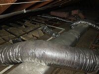
One thing I've discovered that probably should be fixed before adding anymore registers is the (single) return duct is very poorly spec'd and installed. It's only 14" diameter flexduct which, according to what I've found on line, will only flow around 700 cfm. It's also a poor installation with a sharp bend right where it connects to the blower housing (see photo). The return register is in a hallway in about the middle of the house (where I would expect it to be) and ceiling joist /hallway width limit how large the opening can be. It seems adding another return would be a good idea but I haven't been able to find a supply of large duct pieces like this that would allow me to 'Y' two returns to the blower. Any ideas on how to go about this? The sketch is a not-to-scale rough idea of the set up.

It would seem the easiest way to do this would be to install another 14" duct which would be installed seceral feet to the left of the first photo and maybe try to improve the original return so it doesn't have such a drastic bend. Or re-do the original with rigid ducting? I can't even find 14" flexduct for sale....
 

Attachments

  • IMG_1923.JPG
    IMG_1923.JPG
    862.8 KB · Views: 34
  • IMG_1917.JPG
    IMG_1917.JPG
    876.1 KB · Views: 37
  • AC Blower-Evap layout.pdf
    254.1 KB · Views: 9
Last edited:

CraigStu

Well-known member
Joined
May 22, 2014
Messages
4,053
Location
Blacksburg, Va
If you can find the ducting I am thinking remove the existing return duct from that box and run it into a new opening cut into the side of the box. (top of the box in your drawing). That will reduce the bend from a 180 to a 90 which should help. If you leave the return duct the same length it is now, your 90 bend could have a nice wide radius. Then you could use the existing hole, possibly w/ an adapter, to a more commonly available size ducting, for an additional return. If there is a reasonable spot in the house for another return somewhere to the left of your drawing that would make things easy.
 

yeldogt

Well-known member
Joined
Jan 2, 2012
Messages
18,184
Poor thing ...... and it looks like it's in an unconditioned space
 
OP
M

MikeC55

Well-known member
Joined
Nov 1, 2020
Messages
430
Location
CT
Thanks Craig, I like that idea! I know I've seen large take-offs that I could add to the existing box and route the new duct to the existing plenum (with adapter change or new plenum) and then move the existing 14" duct to a new return plenum (to the left in photo) which would result in a much straighter duct run.
It is in unconditioned space but I suspect it's pretty typical for the Northeast when adding AC to the 2nd floor of a house (as a separate system from 1st floor). In this case coming down from the ceiling was much easier (cheaper) than going up through the floor from basement, I suspect.
 

75gmck25

Well-known member
Joined
Jul 21, 2014
Messages
1,328
Location
Alexandria, VA
I have a similar setup in my Virginia house, with A/C in the attic and 12 ducts coming down (six to each floor). The only big difference is my attic is spray foamed so its conditioned space. I also have only one large return duct, but it is at least as big as the entire end of the A/C unit (maybe 20"x20") and it just makes a right angle turn and goes into the ceiling of the hallway at the top of the stairs. I have radiator hydronic heat, so the attic unit is A/C only.

When I owned a house in Texas it seemed to be really tuned for A/C. The one story house had a cold air return in each bedroom, and two large returns in the central part of the house. I am considering adding return ducts to the upstairs bedrooms in my Virginia house, feeding into the existing plenum. The house has relatively small undercuts at the bottom of each bedroom door and this reduces air circulation when the doors are shut. It may not be that difficult a job to add more returns, since with the conditioned attic I can use round metal duct for each return.
 
OP
M

MikeC55

Well-known member
Joined
Nov 1, 2020
Messages
430
Location
CT
So, I did add a 2nd return to the evaporator unit; another 14" round flex duct. I also added the enclosed porch and 2 batthrooms to the system; 7" duct going to a distribution box that splits off a 7" duct to enclosed porch and 5" flex going to the far bathroom (around 20'). A 5" flex was added to the main trunk and goes about 6 feet to the near bathroom. I also installed dampers for these and have them adjusted so everything seems to flow well. This is the first summer I've been able to see how the system performs and I must say on the hottest days, it does struggle to keep the house down to 71 (runs esentially full time). It is an old system (installed 2001), and who knows when it was last checked out thoroughly.

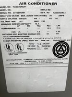
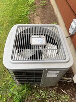
But one thing that bothers me is the seemingly small size of the condenser compared to what I see on other, similar sized houses in the neighborhood. I attached a photo of the label on it and I don't see anything that would indicate the tonnage. It measures roughly 25 x 25 x 25", which seems rather small for a 3 ton system. The evap unit label does translate to 36,000 BTU ( 3 ton), according to the manual I found on Google for the model number. I'm hoping to just make it through the summer as I know the system is on borrowed time and plan to install new equipment in the off season. I do plan to have a tech take a look in case it's low on refrigerant, etc. but would appreciate any input if this is a poor match up of evap and condesner.
 

Attachments

  • Condenser label.jpeg
    Condenser label.jpeg
    441.8 KB · Views: 17
  • Condenser.jpeg
    Condenser.jpeg
    831.1 KB · Views: 13
  • Evaporator.JPG
    Evaporator.JPG
    796.8 KB · Views: 8
  • 3 ton.jpg
    3 ton.jpg
    177.1 KB · Views: 14
OP
M

MikeC55

Well-known member
Joined
Nov 1, 2020
Messages
430
Location
CT
I thought I had posted this in HVAC section. Moderator, can you move it?
 
OP
M

MikeC55

Well-known member
Joined
Nov 1, 2020
Messages
430
Location
CT
Thanks! I guess this helps explain why the unit is struggling in a 2000 sq ft house. It must have been a relatively low budget install back in the day.
 

PoorUB

Well-known member
Joined
Mar 29, 2021
Messages
11,704
Location
Fargo, ND
Thanks! I guess this helps explain why the unit is struggling in a 2000 sq ft house. It must have been a relatively low budget install back in the day.
I agree that it should be 3 ton, maybe 3-1/2 ton.

Another thought, have you looked at your attic insulation? More insulation is rarely a bad deal.
 
OP
M

MikeC55

Well-known member
Joined
Nov 1, 2020
Messages
430
Location
CT
The insulation is fiberglass R30 batts. but flex duct is only R8. I do plan to add another layer of R18 or R30 but figured it would be best to wait until after replaing the system. Maybe the duct wrok is OK and adding a layer of fiberglass over it will help too. The roof does have proper ridge vent and soffit vents but it still gets quite warm up there. Manye it would be worth installing one of those powered attac fans?
 
To avoid these ads, REGISTER NOW!
Top Bottom