To avoid these ads, REGISTER NOW!

Hydraulic Fitting Wrench Sizes

InjectorService

Well-known member
Joined
Dec 11, 2019
Messages
266
Location
Canada
I've started a project on a Kubota skidsteer which has led me to want for some angle wrenches. I will be purchasing Tekton. But I need to know what sizes.

I think the best suited place for these is on hydraulics, which would be bigger sizes. Is there a reason I should buy the smaller sizes too? They have a 1/4 - 1" set but I can't think if why I'd ever need the smaller sizes in this style wrench.

Also do I need metric? Are the Kubota hydraulic fittings requiring metric sizing?
 
To avoid these ads, REGISTER NOW!

bigfunwmu

Well-known member
Joined
Oct 26, 2013
Messages
411
Location
S. MN
Typical sizes are inch, but newer stuff seems to be going to metric size wrenches on SAE fittings.

traditional inch JIC sizes for hose ends are:
-4 9/16
-6 11/16
-8 7/8
-10 1"
-12 1-1/4
-14 1-3/8
-16 1-1/2

It is worth having between sizes for jump size fittings or oddball stuff, more likely to see oddball stuff in tight places where some engineer used something goofy to make it fit.

For O-ring face, even with SAE threads many of the hex sizes have gone metric. These wrench sizes are from Gates

-4 17mm
-6 22mm
-8 24mm
-10 30mm
-12 36mm
-16 41mm
 
OP
I

InjectorService

Well-known member
Joined
Dec 11, 2019
Messages
266
Location
Canada
Typical sizes are inch, but newer stuff seems to be going to metric size wrenches on SAE fittings.

traditional inch JIC sizes for hose ends are:
-4 9/16
-6 11/16
-8 7/8
-10 1"
-12 1-1/4
-14 1-3/8
-16 1-1/2

It is worth having between sizes for jump size fittings or oddball stuff, more likely to see oddball stuff in tight places where some engineer used something goofy to make it fit.

For O-ring face, even with SAE threads many of the hex sizes have gone metric. These wrench sizes are from Gates

-4 17mm
-6 22mm
-8 24mm
-10 30mm
-12 36mm
-16 41mm
Fantastic information! That's exactly what I was looking for! Looks like I may need to buy metric eventually anyways.
 

AJHD

Well-known member
Joined
Jan 4, 2020
Messages
3,057
Location
AZ
Well, I just ordered SAE in 3/8-1 1/4" sizing. I hope that should do. I'm thinking there will be many other uses for these wrenches as well.

I can't speak for Kubota, but I assume like most other equipment (ie. CAT), all newer/modern versions are mostly (if not entirely) metric.
That said, I also bought a set of angle wrenches 3/8" to 1-1/4". Unfortunately I didn't get to use them a lot before leaving CAT, but the few times I was able to use them they worked great.

Point being that you might need some metric eventually and also some larger SAE sizes, but the 3/8" to 1-1/4" set should hold you over for now, especially for working on a skid steer.

You will also want to keep your adjustable wrenches on hand. You will often need 2 wrenches to tighten fittings or use an adjustable when a wrench doesn't fit. I used adjustable wrenches all day every day working at CAT.
 

Attachments

  • IMG_20230615_090252-2.jpg
    IMG_20230615_090252-2.jpg
    571.1 KB · Views: 161
  • IMG_20230601_151348.jpg
    IMG_20230601_151348.jpg
    1.3 MB · Views: 159

Hohn

Well-known member
Joined
Aug 25, 2016
Messages
2,720
Location
Diesel Central, Indiana
Typical sizes are inch, but newer stuff seems to be going to metric size wrenches on SAE fittings.

traditional inch JIC sizes for hose ends are:
-4 9/16
-6 11/16
-8 7/8
-10 1"
-12 1-1/4
-14 1-3/8
-16 1-1/2

It is worth having between sizes for jump size fittings or oddball stuff, more likely to see oddball stuff in tight places where some engineer used something goofy to make it fit.

For O-ring face, even with SAE threads many of the hex sizes have gone metric. These wrench sizes are from Gates

-4 17mm
-6 22mm
-8 24mm
-10 30mm
-12 36mm
-16 41mm
The fluid power industry is one of the ugliest shotgun weddings of metric and SAE ever.
ISO 6149 metric port will get a fitting threaded into it with a metric hex and SAE thread for the ORFS.

Then the hose will thread onto that male union with the same SAE thread and it might have metric OR SAE hex.

What a mess.
I wish they'd just kind of switch it all over to metric now since just about everything else is. That way I can keep my SAE tools in retirement where they prefer to be.
 

Firebrick43

Well-known member
Joined
May 12, 2015
Messages
14,227
Location
West central Indiana
The fluid power industry is one of the ugliest shotgun weddings of metric and SAE ever.
ISO 6149 metric port will get a fitting threaded into it with a metric hex and SAE thread for the ORFS.

Then the hose will thread onto that male union with the same SAE thread and it might have metric OR SAE hex.

What a mess.
I wish they'd just kind of switch it all over to metric now since just about everything else is. That way I can keep my SAE tools in retirement where they prefer to be.
WHAT? All the metric ports i machined were always metric threads?

https://www.goodyearrubberproducts....0/Parker Tube Catalog 4300examin1.Page476.pdf

Parker docs confirm it.
 

AJHD

Well-known member
Joined
Jan 4, 2020
Messages
3,057
Location
AZ
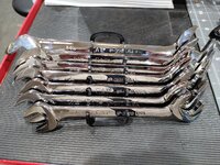
I haven't seen these yet in person and unfortunately the sizes are limited. But HF recently put out some new Icon angle wrench sets. They're a possible option for anyone wanting to buy locally. I hope they release an additional set with larger sizes.
 

Attachments

  • IMG_20230809_200135.jpg
    IMG_20230809_200135.jpg
    141.2 KB · Views: 134

bigfunwmu

Well-known member
Joined
Oct 26, 2013
Messages
411
Location
S. MN

nadogail

Well-known member
Joined
Jan 23, 2009
Messages
32,057
Location
Coronado, CA
When I worked as a Field Service Tech for a hydraulic shop. the wrenches i bought from Harbor Freight fit everything.
 

Sumboodie

Well-known member
Joined
Mar 20, 2021
Messages
10,762
Location
AK
Reminds me of 80s General Motors products! Don't get me wrong...I love em...but that was a terrible mix of standard and metric! Haha
Joel
90s. Least the 80s GMs I've worked on, could tear probably 75% of the truck apart with a 1/2" and 9/16"
 

Callelle

Well-known member
Joined
Feb 3, 2022
Messages
644
Location
Depew NY
I haven't seen these yet in person and unfortunately the sizes are limited. But HF recently put out some new Icon angle wrench sets. They're a possible option for anyone wanting to buy locally. I hope they release an additional set with larger sizes.
I like that they came out with them, but aside from only being able to choose from small sizes, I was hoping for some sort of anti-slip. Capri has anti slip grooves on theirs, though I also wish they had more bigger sizes.
 
To avoid these ads, REGISTER NOW!

dscheidt

Well-known member
Joined
Apr 26, 2017
Messages
2,909
90s. Least the 80s GMs I've worked on, could tear probably 75% of the truck apart with a 1/2" and 9/16"
this mix started in the 70s. The Chevette was all metric, which was what 75?, and was the first metric car from detroit.

By the late 70s, all three detroit automakers were using metric for almost all new designs, but existing stuff didn't get changed, and some designs lasted until the late 90s. in the 80s, gm and ford (probably chyrsler, too, but outside of my experience) started using fasteners with metric heads and sae threads, apparently out of some customer (probably uncle sam) pressure to have fewer tools needed. that led to all sorts of horrible mixing, when someone would use a normal hardware store sae bolt instead of the goofy one. the gradual changeover lead to things like starters that bolted to the engine with sae bolts, because it always had, but the revised solenoid has metric screws for the wires. Add to that the aftermarket which didn't always change at the same time, and the whole thing was just a horrible mess.
 

Sumboodie

Well-known member
Joined
Mar 20, 2021
Messages
10,762
Location
AK
this mix started in the 70s. The Chevette was all metric, which was what 75?, and was the first metric car from detroit.

By the late 70s, all three detroit automakers were using metric for almost all new designs, but existing stuff didn't get changed, and some designs lasted until the late 90s. in the 80s, gm and ford (probably chyrsler, too, but outside of my experience) started using fasteners with metric heads and sae threads, apparently out of some customer (probably uncle sam) pressure to have fewer tools needed. that led to all sorts of horrible mixing, when someone would use a normal hardware store sae bolt instead of the goofy one. the gradual changeover lead to things like starters that bolted to the engine with sae bolts, because it always had, but the revised solenoid has metric screws for the wires. Add to that the aftermarket which didn't always change at the same time, and the whole thing was just a horrible mess.
Had a 98 Dodge truck. Would need a whole toolbox for most projects between the SAE and metric mishmash.
 

Hohn

Well-known member
Joined
Aug 25, 2016
Messages
2,720
Location
Diesel Central, Indiana
American manufacturers slowly figured out that if you use fasteners that the rest of the world does (i.e. Metric), you can save money. It turns out that with global supply chains, it matters whether a couple hundred thousand a year of a certain part are made vs a couple million, and that difference translates into the cost of the BOM.
 

All

Well-known member
Joined
Mar 28, 2013
Messages
607
After doing a search on GJ for oring face seal fittings (orfs), the results kept sending me to this thread.

I have a two stage import hydraulic (manual) pump with an output male elbow fitting that appears to be an orfs with a metric 6.0 x 1.8 o-ring size called out in the parts diagram... thread type unknown.

With it came an import cylinder with welded on male ******* also appearing to be orfs, but with a metric 7.5 x 1.8 o-ring size called out in the parts diagram... thread type unknown.

Both the pump and the cylinder shipped with threaded caps on the ports, and the caps are different on the inside (thread depth to the end of the cap) but appear to interchange between ports, suggesting that the threads may be the same, even if the sealing surface o-rings are not the same.

The easiest solution would be to order the OEM hose assembly for the pump and cylinder, but it is an import, and the wait time for such a hose assembly was quoted as AT LEAST 4 months, with no guarantees that the part would ever arrive.

I thought, no problem, I can always get a hydraulic hose locally. Not so. First, the 10,000 psi rating appears to be a rarity. And even where that is surmountable, once stepping outside the realm of JIC, it is back in the land of rarity it seems.

This rarity appears to include transitional fittings to get from orfs to JIC.

It doesn't help that both the pump and the cylinder are terminated with male threads, which means I need females on the hose. Swiveling females (that need not swivel once tightened).

I am currently dog paddling out of my depth, but am hoping that continued research will bring me to a better understanding of how incompatible fittings from China, where most things are made that I can afford, are interfaced with locally obtainable hydraulic hoses and fittings.

Any direction and advice is appreciated.
 

bigfunwmu

Well-known member
Joined
Oct 26, 2013
Messages
411
Location
S. MN
After doing a search on GJ for oring face seal fittings (orfs), the results kept sending me to this thread.

I have a two stage import hydraulic (manual) pump with an output male elbow fitting that appears to be an orfs with a metric 6.0 x 1.8 o-ring size called out in the parts diagram... thread type unknown.

With it came an import cylinder with welded on male ******* also appearing to be orfs, but with a metric 7.5 x 1.8 o-ring size called out in the parts diagram... thread type unknown.

Both the pump and the cylinder shipped with threaded caps on the ports, and the caps are different on the inside (thread depth to the end of the cap) but appear to interchange between ports, suggesting that the threads may be the same, even if the sealing surface o-rings are not the same.

The easiest solution would be to order the OEM hose assembly for the pump and cylinder, but it is an import, and the wait time for such a hose assembly was quoted as AT LEAST 4 months, with no guarantees that the part would ever arrive.

I thought, no problem, I can always get a hydraulic hose locally. Not so. First, the 10,000 psi rating appears to be a rarity. And even where that is surmountable, once stepping outside the realm of JIC, it is back in the land of rarity it seems.

This rarity appears to include transitional fittings to get from orfs to JIC.

It doesn't help that both the pump and the cylinder are terminated with male threads, which means I need females on the hose. Swiveling females (that need not swivel once tightened).

I am currently dog paddling out of my depth, but am hoping that continued research will bring me to a better understanding of how incompatible fittings from China, where most things are made that I can afford, are interfaced with locally obtainable hydraulic hoses and fittings.

Any direction and advice is appreciated.

Fittings that meet the O-ring face standards don't have metric o-rings.

Buying a fitting to get from standard O-ring face (which you don't have) to JIC (which isn't rated to 10,000 PSI in any size) won't help you.

Your fittings are weird just to prevent people from screwing random **** on there and killing yourself, and your family or estate suing the manufacturer of the thing you misused.
-----------------------------
First thing you need to figure out is what you actually have for fittings. Get a set of metric and standard thread pitch gauges, and a caliper. If you can figure out what you have, you may be able to find somebody who makes jack hose (10k psi hose in small diameters is commonly called jack hose) with the goofy ends you need. Otherwise you're stuck waiting for the goofy Chinese hose to match the goofy Chinese fittings your stuff has.
 
Last edited:

All

Well-known member
Joined
Mar 28, 2013
Messages
607
First thing you need to figure out is what you actually have for fittings. Get a set of metric and standard thread pitch gauges, and a caliper.
@bigfunwmu

Here are the measurements that you suggested that I take. Thank you for your interest and any insight you can provide.

Using three thread pitch gauges...
A. Metric
B. Fractional
C. "SAE"

I found the 1.5 mm per thread pattern on the metric thread pitch gauge appeared to match the best.

Albeit, while the thread crown/crest points matched (aided by a flashlight back lighting the gauge and the threads), and the gauge nested fully into the valley/root of the threads, the thread angle appears more U shaped rather than V shaped, which allowed the 1.5 mm gauge to shift axially a little bit back and forth between thread flanks more than I am used to seeing.

Several attempts were made to find a better fit from the entire fan of choices in all three thread gauges, with 16 TPI being a distant second best on the fractional/SAE gauges, yet the crest cadence was off, evidenced after about 5 threads.

Thus, the closest actual match where the crests aligned for the entire length of threads was the 1.5 mm per thread gauge.

The threads appear to be straight... in other words, I could not detect any type of pipe like taper to the root diameter that grew in size as the threads advanced toward the body of the fitting. I clumsily attempted to verify this observation with the dial caliper, as described below.

Using a 6" dial caliper (wish I had better/smaller), reset to zero, measuring in thousandths, and converted to millimeters...

1. The overall diameter, crest to crest was 0.551" / 14 mm

2. The root diameter, root to root, was 0.500" / 12.7 mm at the entrance thread, and again was 0.500" / 12.7 mm at the terminating thread.

Based on your earlier response above, I will no longer call these fittings O-ring face seal, but they do have an O-ring, which appears to seat and seal in the flat face of the fitting, within the machined perimeter ring ledge that helps keep the O-ring in place.

Both the pump fitting and the cylinder fitting have raised machined ledges that appear to assist in locating the face mounted sealing O-ring. However, while the raised machined ledge on the pump fitting is around the perimeter, capturing the O-ring by surrounding the outside diameter of the O-ring, by distinct contrast, the raised machine ledge on the cylinder fittings is within the inside diameter of the O-ring, with no raised ledge on the outside diameter such as what the pump has. Likewise, in continued contrast, the pump fitting has no raised ledge capturing the inside diameter of the O-ring.

I have observed photos of ORSF fittings that have two machined raised ledges to keep the O-ring in place that capture both the inside AND the outside diameters of the O-ring, rather than just one OR the other, like the fittings I have.

I measured the metal dimensions that the O ring seats within and seals on the pump fitting.

3. Inner diameter of the fluid orifice within the fitting, surrounded by the O-ring: 0.197" / 5 mm

4. Maximum diameter of the O-ring seat, excluding the machined perimeter ring ledge that contains the O-ring: 0.370" / 9.4 mm

5. Face width of the outer perimeter raised machined ring ledge that contains the O-ring: 0.065" / 1.65 mm (approximated, as the outer walls of this ledge taper into the first thread)

The foregoing measurements apply to the single outlet fitting on the 2 stage manual pump.

The following measurements apply to the single acting hydraulic cylinder fittings (there are two fittings, comprised of welded on male *******, where one ****** appears to be for a force gauge, and the other ****** is to receive the pressurized oil from the pump).

The metal dimensions that the O-ring seats within and seals on the cylinder fittings are as follows:

6. The overall diameter, crest to crest was 0.550" / 14 mm

7. The root diameter, root to root, was 0.500" / 12.7 mm at the entrance thread, and again was 0.500" at the terminating thread.

8. Inner diameter of the fluid orifice within the fitting, that is also the inner diameter of the machined raised ledge that retains and centers the O-ring: 0.197" / 5 mm

9. Maximum diameter of the O-ring seat, including the machined interior ring ledge within the inside diameter of the O-ring: 0.455" / 11.56 mm (This is approximated, as the outside edges taper off into the first thread)

10. Face width of the inner raised machined ledge defining the fluid orifice, surrounded by the O-ring that this ledge helps locate: 0.055" / 1.4 mm

Summary:

The pump male fitting and the cylinder male fitting have the same 1.5 mm thread pitch.

Both also have seats for O-rings on their fitting faces.

However, the location of the raised machined ledges that retain the O-ring in position differ between the pump fitting and the cylinder fittings. The pump fitting has a machined raised ledge on the perimeter of the face, outside of the O-ring, with no ledge or protrusion at the orifice. On the other hand, the cylinder fitting has a machined raised ledge that defines the orifice, on the inside of the O-ring, without any perimeter raised ledge on the outside of the O-ring.

Another difference is that the male ****** fittings on the cylinder have fewer threads, 5 on one fitting and 6 on the other, while the pump male fitting has 10 threads. The cylinder fittings with fewer threads appear to have yet another O-ring land at the base of the threads, where an O-ring is rolled over the threads and seats like a hula hoop surrounding the threadless root diameter of the ******. The fewer threads on the cylinder fittings appear to be intentional, so as to accommodate this additional O-ring at the neck of the ******, just below the threads.


Finally, the metric hex wrench size to open the threaded caps is 17 mm. The interiors of the caps between the pump and the cylinder appear to differ from each other in terms of number of threads, but they both have the same 1.5 mm thread pitch.
 

Hohn

Well-known member
Joined
Aug 25, 2016
Messages
2,720
Location
Diesel Central, Indiana
1.5mm thread pitch is very common in metric hose fittings, even as they scale in size.

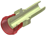
If it uses an o-ring sealing element that is compressed on its face with axial load, it's an ORFS fittings. Full stop. It might not be SAE J1453, but it's definitely an ORFS fitting.

But there are several standards that are ORFS. J1453 is the common thing in the USA and uses fractional threads on the hose ends. ISO picks this up as ISO 8434.


There is a Chinese standard that likely aligns with what you have on your equipment: GB/T 9065.3
1701435817612.png

This Chinese standard uses metric threads with an ORFS type design but with "standard" inch tube or hose sizes (dash sizes) as you'd be familiar with.
 

All

Well-known member
Joined
Mar 28, 2013
Messages
607
@Hohn

Thank you immensely.

Thanks to you, I am now armed with a new search term: "MFFS" (Metric Flat Face Seal).

I do not have a hydraulic fitting crimper at home, and NO hydraulic shop that I have talked to will take on the liability of crimping together a hose whose parts they did not supply in the entirety (citing insurance reasons, which are understandable).

From the help that I have received thus far, it appears that I should now be searching for a 690 Bar female swivel end (both ends) MFFS jack hose about 1 meter long.

Alternatively, transitional fittings that mechanically translate from MFFS to a fitting standard more commonly available in the US would work also, provided that all components involved were rated to 10K PSI.

Ideally, an MFFS female to some type of quick release coupler with a self sealing ball bearing to stop flow when decoupled, at both the pump and the cylinder end, would be the most convenient for servicing either the pump or the cylinder as needed when (not if) the glands fail.

That is why I have the present new pump and new cylinder... they were cheaper to buy than rebuilding the leaking pump and cylinder they are replacing (also import, of unknown brand or origin, that has yet different fittings, making the existing hose between them that a previous owner cobbled up not useable).
 
Last edited:

Steve_P

Well-known member
Joined
Sep 15, 2010
Messages
5,188
American manufacturers slowly figured out that if you use fasteners that the rest of the world does (i.e. Metric), you can save money. It turns out that with global supply chains, it matters whether a couple hundred thousand a year of a certain part are made vs a couple million, and that difference translates into the cost of the BOM.

I know this is an old thread, but my first time reading it.

The reason companies like Ford went to metric in the US market isn't because using metric fasteners was cheaper, on the cost per fastener, they were buying millions of inch fasteners in the US, it's because they went to global engine and vehicle platforms. And of course, using metric just plain makes sense.

Decades ago I read an article on this, and the explanation was that if you are going to sell the same basic vehicle, or even engine, on 4 continents and in dozens of countries, it doesn't make sense to have a set of drawings for the US using inch fasteners, and then a set for the rest of the world in metric, for essentially the same product. With two sets of drawings, every time you make an engineering change, this means twice the work, you have twice the fastener part numbers (so there is savings there), etc. It's just an unnecessary PITA for a global company to use inch fasteners.

Edit- my dad had an '82 Buick and it used some metric fasteners underhood. I don't remember the details other than it took four sets of sockets and two sets of wrenches to work on it.
 

All

Well-known member
Joined
Mar 28, 2013
Messages
607
If I recall correctly, General Motors was the first US domestic automotive manufacturer to introduce metric fasteners in production, in dribbles and drips, beginning in 1975.

Some may remember how hot of a topic US conversion to the metric system was in the early 70's, during the Nixon Administration, for purposes of determining what standard should be taught with publicly funded schools.

Simultaneously during that period, while the smallest cars we had were Vegas and Pintos, Honda brought the Civic to our shores, just in time for the two so called "fuel crises" events we weathered. Combined with the Datsun B510 and Z series, and the Toyota HiLux, Cressida, and Corolla... any auto shop could no longer escape having a full set of metric wrenches and sockets in their drawers.

Fast forward 50 years later, and 5 hydraulic specialty shop back and forth telephone conversations later, I cannot find anyone in the hydraulic industry to supply a jack hose that can adapt to male Metric Flat Face Seal fittings, including the Malone Specialty shop in Ohio that @Hohn linked to. They can supply 2500 psi fittings, not 10,000 psi jack hose fittings.

I'm fittingucked.

Looks like a four month wait for a container ship.

I guess this is another reason why domestic companies who can afford it stick with Enerpac.
 

dscheidt

Well-known member
Joined
Apr 26, 2017
Messages
2,909
If I recall correctly, General Motors was the first US domestic automotive manufacturer to introduce metric fasteners in production, in dribbles and drips, beginning in 1975.
the chevette was fully metric. pretty much every new design from GM following that was also metric. Chrysler and Ford followed suit pretty quickly, but existing stuff kept being made in the threads it had already had, and so most US cars had a mix and match set of fasteners until the late 90s. there's was also some horrible stuff that had bolts with sae threads, but metric heads.
 

All

Well-known member
Joined
Mar 28, 2013
Messages
607
One hydraulic shop suggested that I saw off the welded on male metric flat face seal *******, and tap Female Pipe threads into the cast base of the cylinder.

It is boiling down to this thread, and a thread on Chinese tractors on tractor-by-net, being the only two results that Google reveals on what I am looking for. This is insane. I am willing to hard pipe the line between the pump and the cylinder, and center the cylinder in the press to make it non-slideable.

I can find metric flat face seal MALE fittings on several Made in China fitting websites, but no Female fittings, other than internal barbed hose type. What do people do with import presses when they need to replace a hydraulic hose?
 

cherrybomb

Well-known member
Joined
Oct 18, 2016
Messages
893
Location
Near Madison Wi.
This is just me,doesn't work for everyone in every situation. Whenever I buy a new machine,I look it over.I ask myself,do I have the tools to fix,adjust it.If not its time to research and up grade.For instance,my situation, bought a new Kubota lawn tractor,metric and some sizes I didn't have,like blade nut.I'm ready.You could do the same for your skid steer.Piece it.Of course the Professional needs a lot more selection. Everyone's situation is different but you don't want to mess a fitting up by the wrong might work wrench
 

bigfunwmu

Well-known member
Joined
Oct 26, 2013
Messages
411
Location
S. MN
One hydraulic shop suggested that I saw off the welded on male metric flat face seal *******, and tap Female Pipe threads into the cast base of the cylinder.

It is boiling down to this thread, and a thread on Chinese tractors on tractor-by-net, being the only two results that Google reveals on what I am looking for. This is insane. I am willing to hard pipe the line between the pump and the cylinder, and center the cylinder in the press to make it non-slideable.

I can find metric flat face seal MALE fittings on several Made in China fitting websites, but no Female fittings, other than internal barbed hose type. What do people do with import presses when they need to replace a hydraulic hose?
Press hoses, especially in a home-shop press, don't fail often. They are typically indoors and protected from UV, and they don't get moved around much so they don't rub through... Most of those will last 20+ years without issue.

If you have a local machine shop that has decent rates, have them cut you a couple adapters out of bar stock. Female metric threads with a flat face on one side, male or female extra long NPT threads on the other side depending on which normal-ish Enerpac hose you can get.
 

All

Well-known member
Joined
Mar 28, 2013
Messages
607
That is a great idea, and thinking along those (hydraulic) lines, I actually currently have the correct female metric M14x1.5 threads already machined in the form of the thick metal caps presently sealing the ports, as shipped with the pump as well as the cylinder.

Could I not scrub the remainder of the paint off of these steel caps, remove the O rings at the end of the caps (one O-ring was missing anyway, so I've already removed and replaced O-rings within these caps, using Viton) then drill a 6 mm hole through the center of these caps, then insert a 6 mm diameter dowel of copper through the hole I drilled, and then weld on a steel NPT adapter that would would accept a QR coupler for a jack hose?
 

bigfunwmu

Well-known member
Joined
Oct 26, 2013
Messages
411
Location
S. MN
That is a great idea, and thinking along those (hydraulic) lines, I actually currently have the correct female metric M14x1.5 threads already machined in the form of the thick metal caps presently sealing the ports, as shipped with the pump as well as the cylinder.

Could I not scrub the remainder of the paint off of these steel caps, remove the O rings at the end of the caps (one O-ring was missing anyway, so I've already removed and replaced O-rings within these caps, using Viton) then drill a 6 mm hole through the center of these caps, then insert a 6 mm diameter dowel of copper through the hole I drilled, and then weld on a steel NPT adapter that would would accept a QR coupler for a jack hose?
You might, but I know how good a welder I am (not) and wouldn't trust my skills to make something that holds up.
 

All

Well-known member
Joined
Mar 28, 2013
Messages
607
Judging by the haphazard and wandering beads of the existing welds on this Made in China pump and cylinder, I wouldn't sell yourself so short.

I might be more apt to trust your welds (and my welds, which could be worse) over the welds holding the ******* into the bored base casting (likely British pipe thread on the inserted and welded up ends of these *******, with the other and being Male M14x1.5 flat face seal with an inner O-ring locating wall, but no outer wall.) It is anyone's guess which welds would hold up.

One of the ways that I have been thinking about to "pressure test" any welds that would marry an NPT fitting to the original metal threaded cap... is to buy a hardened M14x1.5 bolt, Property Class 12.9 or 10.9. Then take a couple of quick measurements...

1. The thickness of the existing O-ring at the inside top of the cap, that mates to the flat face of the metric ******.

I would seek to know the relaxed height of this O ring, and would need to know what the compressed height of this O ring is expected to be when the corresponding female threaded flat face is fully tightened. Is the O-ring compressed by 40%? 50%? 60%?

Does the O-ring compression height change when constrained by an outer diameter wall ledge, such as with the pump outlet ******, versus the cylinder ******* that have an inner diameter wall ledge (presumably to prevent an overly compressed O-ring from getting forced into the base bore leading to the cylinder)?

Once I have an idea about the compressed height of the O-Ring when in the sealing mode, I would then measure

2. The inside height of the metal caps that are getting ready to walk down the aisle in a hot and hokey marriage to an NPT fitting, that won't melt hearts, but hopefully will adequately melt into each other's flats, but not too much so (hence the temporarily placed copper dowel to preserve the orifice diameter while welding, and wick away any over accumulation of heat).

The inside height of the cap, minus the estimated compressed height of the O-ring when sealed, would be how far down I would mark the threads of the hardened M14x1.5 "pressure test" bolt.

After the honeymoon cool down of the married fitting, I'd hook up a jack hose and screw the metric cap end onto the metric test bolt, down to the depth of threads previously marked from the measurements taken in 1 & 2 above.

While I could use a grease gun or a porta power pump, I might as well use the new hydraulic pump I am trying to adapt to my old press frame. (I'll explain that cart before the horse a bit later on in this post)

Dropping a weighted square milk crate into the bottom of a spare rain barrel, watering trough, or garbage can half full of water, I would then place gallon jug of used transmission fluid (I save all used transmission fluid, for many purposes, some of which are popular hacks on GJ) on top of the already submerged milkcrate, such that the water level in the barrel covered about 85% of the gallon jug of transmission, also submerged, but for the 15% crown of the gallon bottle above the water's surface, to keep oil and water from mixing.

Into the gallon of ATF I would drop the test bolt attached to the married by weld fitting attached to the jack hose (10K WP / 20K BP) attached to a T fitting branching to a 15,000 PSI gauge and the pump. Then I'd slowly pump up to a limit of 80% of the gauge (12K).

Presumably, the jack hose, with a 20,000 PSI burst rating, can handle one test excursion to 12,000 psi, but if not, then maybe I can mitigate that by threading the jack hose through a spiral wound 2" diameter fuel hose temporarily for the test.

I'm just spit balling ways to test such a weld, with the expectation that if the weld were to let go, the divorce would make the test bolt a bullet, and the jack hose a bullwhip.

Circling back to the cart before the horse... unlike the ******* welded on to the cylinder, the elbow of male M14-1.5 flat face fitting on the pump is removeable, and I have removed it, to find tapered female pipe threads in the cast block manifold of the pump.

HOWEVER, I don't have the gauge on hand to distinguish between a 55° thread flank taper versus a 60° thread flank taper, and don't have the experience in fittings to be able to judge if these female pipe threads are British or National. I need to not only know this, I need to know the best way to determine this.

And of course, I am open to advice and admonishment for any of the ideas that I'm just spit balling here.

Before any marriage takes place, I'm trying to keep my options open, and have given an embarrassingly lusty eye to light truck lug nuts, which also happen to be M14x1.5. The locking, closed end type are both long and thick, giving plenty of material to work with, cutting off the locking end, cutting off the tapered or swiveling end (depending on of the lug nut is for hub centric or lug centric wheels).

I could buy one new lug nut, from an OEM, if I wanted assurance of property class strength in the material it is made of... not that I think it really matters, but what the heck. Either way, the machining of metric threads is already done for me.

The only significant difference between using the lug nut versus using the original caps... is that the original caps will provide a built in flat face covering the male end of the flat face seal fitting that I am trying to adapt to. That flat face, with an O-ring compressed in-between, will alleviate reliance on thread sealant between thread flanks of the straight metric threads, which are not designed to seal.

On the other hand, the lug nuts simulate a hollow female threaded coupler, without a flat face, if I use the lug nut full length.

However, If I cross cut the lug nut such that the final height is the same as the caps, and then bore a 6 mm orifice axially through the top of the (closed end type) lug nut, then I would have a more robust (thicker) base upon which to weld an NPT fitting to make this adapter.

I'm still worried about reliance on the O-ring for sealing, since the straight metric threads cannot be expected to seal at all.

Well, that is about where I currently stand on mentally modeling a solution that doesn't involve waiting until April 2024 before maybe/maybe not getting the right hose from the import OEM.
 

bigfunwmu

Well-known member
Joined
Oct 26, 2013
Messages
411
Location
S. MN
For the o-ring compression, when the fitting is fully installed the steel faces of the male and female touch. So the final compressed o-ring height is the depth of the groove below the face of the fitting.

It's nice finding more common threads under the metric bit, gives more options with either BSPT or NPT vs Chinese stuff.

I'll read the rest again later, it's a bit late for it to sink in tonight...
 
To avoid these ads, REGISTER NOW!
Top Bottom