To avoid these ads, REGISTER NOW!

hydraulic jack conversion question

jmiller_2308

Well-known member
Joined
Nov 16, 2013
Messages
563
Location
Shakopee, MN
Short question:
Can I replace the manual pump on my manual jack with fittings to allow me to connect an air/hydraulic pump to it so that I can convert the whole thing to an air/hydraulic jack?

Background:
The jack is on my Harbor Freight motorcycle lift and is essentially a specialized single acting bottle jack. Yes, I've read all kinds of articles about people modifying this lift for air/hydraulic but none of them seem to use the existing jack. The mounting, length, etc. of the jack are such that I'd prefer to be able to use the existing jack and not have to go through the effort of fabricating and installing something new.

After reading and looking at specs it seems as though a 10 ton (10,000 psi) air/hydraulic pump would be a good match for the bottle jack. I have seen one conversion where there person applied such a pump by modifying the existing jack to accept the output of the air/hydraulic pump as per my short question above. However, in that modification they also ended up discarding the original jack's jacket (the reservoir) and plugging various ports. He didn't provide any real description of which ports to block so I'm at a bit of a loss as to how I might modify my jack similarly.

So after contemplating which ports I might need to block I started wondering if I could just modify my jack to replace the plunger with fittings to accept the output from an air/hydraulic pump but leave the current jack's reservoir in tact such that no port plugging would be necessary. It seems to me that as long as both the reservoir in the air/hydraulic pump and the lift jack are full that it should "just work". What am I missing?

This is what the current pump looks like and it. The longer rod is the manual pump and the shorter rod is for a release. I could continue to use this release or I also believe that the air/pump could operate in reverse to bring the lift down.
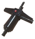
HF-Pump.jpg

For reference, here are the types of air/hydraulic pump I'm considering:

Redline_1500XL_Pump.jpg

or
image_12845.jpg
 
To avoid these ads, REGISTER NOW!

txvwnut

Well-known member
Joined
Jan 1, 2015
Messages
7,662
Location
Bedford, Texas
Uhm no it aint gonna be that easy. You will have to remove or block off the reservoir of and valving as well on the existing jack, as all of that is in the new pump setup you want to use. Just forcing fluid through the pump port will raise the jack but you will have to use the release valve on the jack to get it to lower which will overfill the reservoir on the jack as it will not return the fluid back to the remote pump.
 

Relax

Well-known member
Joined
Nov 22, 2011
Messages
449
Location
GTA, Ontario
I saw a youtube video where someone did the exact conversion you're thinking of. Will have to see if I can find it.
 
OP
J

jmiller_2308

Well-known member
Joined
Nov 16, 2013
Messages
563
Location
Shakopee, MN
Uhm no it aint gonna be that easy. You will have to remove or block off the reservoir of and valving as well on the existing jack, as all of that is in the new pump setup you want to use. Just forcing fluid through the pump port will raise the jack but you will have to use the release valve on the jack to get it to lower which will overfill the reservoir on the jack as it will not return the fluid back to the remote pump.
I wondered about that. My thinking was that with the plunger removed that there would be nothing else in the jack to prevent fluid from coming back out of the cylinder and that as such the added air/hydraulic pump would become the thing that controls the fluid going in and out of the cylinder. By keeping the original reservoir on the jack it would simply create a larger volume for hydraulic fluid.

I had considered that I might want to keep the original release and that it should allow fluid to come out of the cylinder and back into the current jacks reservoir but.... again I was hoping that with the plunger removed that nothing would stop the fluid from feeding back to the added air/hydraulic pump.

I'll have to try an experiment with the plunger removed and see what happens.
 

gmcgeo

Well-known member
Joined
Mar 11, 2019
Messages
3,701
I think it would be cheaper to just buy the air jack? vs buying the parts. idk you will have to price it out once you know whats involved
 

jrsavoie

Well-known member
Joined
Jun 4, 2013
Messages
1,492
Location
North east Illinois
thats easy, they make kits for that. and you can set a small 12v battery underneath or in front that recharges when plugged into truck
Got a battery already for the brakes and the wench. Do you have a link to the kit you referenced?

The Amazon kit is close to price prohibited.
Unless I would need a new jack or something anyway, At that price point, I might be better off selling and buying a trailer already set up with 12 volt hydraulics. Have to check what surpluscenter.com has.
 
Last edited:
OP
J

jmiller_2308

Well-known member
Joined
Nov 16, 2013
Messages
563
Location
Shakopee, MN
Uhm no it aint gonna be that easy. You will have to remove or block off the reservoir of and valving as well on the existing jack, as all of that is in the new pump setup you want to use. Just forcing fluid through the pump port will raise the jack but you will have to use the release valve on the jack to get it to lower which will overfill the reservoir on the jack as it will not return the fluid back to the remote pump.
txvwnut you are correct.

I tried my experiment of removing the plunger and the only oil that would come out of that orifice is stuff that was already primed to go into the cylinder. When I pulled the release the oil cycled back into the jack's reservoir and did not come out the plunger area.

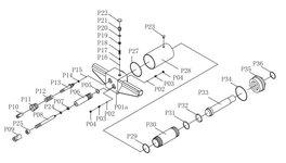
Unfortunately I have no idea how the jack is plumbed in the square box that it sits on but be inquisitive I looked at the parts diagram for the pump and now I wonder if removing the steel ball P02 might allow oil to flow out of the cylinder and back into the reservoir.

HFJack.JPG
 
OP
J

jmiller_2308

Well-known member
Joined
Nov 16, 2013
Messages
563
Location
Shakopee, MN
I think it would be cheaper to just buy the air jack? vs buying the parts. idk you will have to price it out once you know whats involved

I'm not sure about the cheaper part but what you suggest is exactly what many people have done to add air/hydraulic to their HF motorcycle lifts. Unfortunately, to do so requires cutting and welding and although I can do that it is something I would like to avoid if at all possible.
 
OP
J

jmiller_2308

Well-known member
Joined
Nov 16, 2013
Messages
563
Location
Shakopee, MN
Sorry, just thinking out loud and posting as I go, I hope that isn't too annoying.

I was contemplating removing the P02 ball(s) as a means of disabling the check valves.

If I were to remove the check valve that allows oil to be sucked from the reservoir into the pumping chamber that would allow oil to flow from the jack's reservoir back to an added air/hydraulic pump - sounds good but it would only allow the oil in the jack reservoir to flow back and not any oil in that might be in the cylinder - bad.

If I were to also disable the check valve to the cylinder then oil should flow directly out of the cylinder and back into the jack reservoir (because I removed the reservoir check valve) as well as to the added air/hydraulic pump. The potential problem I see is that I believe that means that the jack's reservoir would now be pressurized based on whatever is in/on the cylinder. I think that would be bad and would likely cause the rubber filler plug to pop and oil to spew.

Alternatively I can get oil from the cylinder into the reservoir by opening the release valve and the system would work as a air/hydraulic up and down but only if that release valve were open at the same time that the pump is sucking oil back otherwise I'd have another oil gusher :(.

So I think I finally am comprehending what @txwnut was trying to tell me earlier in this thread. I think it means that I need to block all oil passages to the jack's current reservoir so I assume this means blocking at the oil reservoir check valve and the release valve. To feed oil from the added air/hydraulic using the existing circuit I'd have to disable the check valve to the cylinder and rely on the valving in the added pump instead. The added pump could still come into the jack via the plunger area.

This seems to jive with some pictures I have seen on the web.
 

FredWanaker

Well-known member
Joined
Mar 27, 2021
Messages
1,470
Location
NorCal
https://www.redlinestands.com/catalog/ sells a replacement jack for that unit but they are out of stock. They also sell several other ones, some are air controlled, and they mention some are used to convert other lifts. Why not give them a call. I am sure they have heard the question before.
 

nadogail

Well-known member
Joined
Jan 23, 2009
Messages
32,054
Location
Coronado, CA
You will need some way to convert your air pressure to pump strokes.

I suggest you think like the Chinese;, buy a working unit and reverse engineer it. Then find a way to build it faster and cheaper.
 

BukitCase

Well-known member
Joined
Apr 11, 2017
Messages
1,075
Location
Oregon
Might be less hassle to just jury rig your sawzall to run that foot pump handle :rolleyes: ... Steve
 

txvwnut

Well-known member
Joined
Jan 1, 2015
Messages
7,662
Location
Bedford, Texas
It looks like you could remove PO’s 2,3 and 4 and then block off the passage to the reservoir and then tighten the release on the jack down and it might work.
 
OP
J

jmiller_2308

Well-known member
Joined
Nov 16, 2013
Messages
563
Location
Shakopee, MN
https://www.redlinestands.com/catalog/ sells a replacement jack for that unit but they are out of stock. They also sell several other ones, some are air controlled, and they mention some are used to convert other lifts. Why not give them a call. I am sure they have heard the question before.
I've been to redlinesands as well as sent them email that hasn't been responded to.

The HF replacement stand they sell is manual and happens to be the picture of the black jack I posted above. They also sell a Titan stand version of the jack that is very similar but will not work in my lift without modifications. In particular, a replacement yoke would need to be created or bought from Titan for something well north of another $100. Once together, the Titan jack turns out to be longer than the HF jack which means more cutting and welding on the lift to get it to work. All in, it would be likely close to $500 and a hack to make the Titan jack work and at that point I might as well look for a different lift.
 

FredWanaker

Well-known member
Joined
Mar 27, 2021
Messages
1,470
Location
NorCal
I've been to redlinesands as well as sent them email that hasn't been responded to.

The HF replacement stand they sell is manual and happens to be the picture of the black jack I posted above. They also sell a Titan stand version of the jack that is very similar but will not work in my lift without modifications. In particular, a replacement yoke would need to be created or bought from Titan for something well north of another $100. Once together, the Titan jack turns out to be longer than the HF jack which means more cutting and welding on the lift to get it to work. All in, it would be likely close to $500 and a hack to make the Titan jack work and at that point I might as well look for a different lift.
Notice I said call. Most companies these days don't even answer their e-mails unless they generate it to you. Maybe the person who is supposed to monitor the address left but for every 20 I send on something, maybe 1 person replies.
 
To avoid these ads, REGISTER NOW!

engineer2

Well-known member
Joined
Dec 13, 2009
Messages
11,827
Location
Chicago burbs
I have an air hydraulic pump if you are interested. No idea if it would work for your application, but it was made for a jacking beam for a 4 post lift. That valve might not be needed, but I would include it. It's just dirty from being in storage.


IMG_4394.JPG
 
OP
J

jmiller_2308

Well-known member
Joined
Nov 16, 2013
Messages
563
Location
Shakopee, MN
I have an air hydraulic pump if you are interested. No idea if it would work for your application, but it was made for a jacking beam for a 4 post lift. That valve might not be needed, but I would include it. It's just dirty from being in storage.


IMG_4394.JPG
Thanks for the generous offer. I greatly appreciate it but as it turns out I ordered a non-returnable pump earlier today so I'm all set should this plan work out.

I also disassembled the current jack today and feel pretty confident that I'll be able to block ports sufficiently that I'll be able to essentially make the current jack nothing more than a hydraulic cylinder driven off the external pump. I'll post updates after I get my new pump.
 
OP
J

jmiller_2308

Well-known member
Joined
Nov 16, 2013
Messages
563
Location
Shakopee, MN
Short version of the update is that I got my jack and although the process looks promising when under pressure I'm currently leaking from a fitting that I tried to thread, Details and photos below.

I took apart the lifts jack while waiting for my new air pump to arrive. There are lots of parts but it is actually a pretty simple device.
PXL_20220126_162012589 (Small).jpg

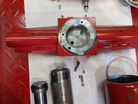
The important bits are in the base of the jack; this picture is looking into what would be the base of the cylinder. Within the cylinder (inner circle the larger hole at the bottom left is the oil into the cylinder and the hole with a screen is the oil out of the cylinder via the pressure release. The outer circle is normally encased in the pump's reservoir. The larger hole on the bottom is where oil feeds out of the reservoir and into the pumping chamber. As part of the conversion I tapped this hole and put a M6x1.0 socket head bolt with red thread seal to close the passage. The smaller hole at about 1:00 is the oil return to the reservoir via the pressure release valve. I decided to rely on the normal release valve to keep this closed and DANG IT, I just realized I forgot to put the ball back in that circuit and perhaps that is part of my leaking issue. The smaller hole at 9:00 is I believe connected to the safety valve. I chose to leave this in place as kind of a back up so things can't blow apart. I figure the worst that would happen is that oil would blow out and back into the old reservoir which would be far better than a high pressure spew or jack blowing apart.

PXL_20220126_162031060 (Small).jpg

Here you can see the other side of the base. The hole on the upper right is where the pump attaches. If you can see it in the picture there is a hole in the upper section and this is the other side of the hole from the reservoir that routes oil into the pump. The other hole is where oil leaves the pump to enter the cylinder. The other larger hole in the lower left part of the base is where the pressure release valve inserts. The hole inside of it that you can see is the other side of the screened hole from the cylinder. There is a smaller hole on the side that you can't see but it is the hole that routes oil back into the reservoir.

PXL_20220126_162046086 (Small).jpg

more in next post....
 
OP
J

jmiller_2308

Well-known member
Joined
Nov 16, 2013
Messages
563
Location
Shakopee, MN
ARGH!!!! I HATE COMPUTERS!!! I ended the above post because I kept getting the "ran into problems" when trying to add pictures. I went so far as rebooting and staring over multiple times. Instead of doing things inline I tried to attach them as files and that only partially works. I HATE COMPUTERS!!!!

Sorry, back to our regularly scheduled followup post. I have no idea if the attached pictures or even this post will make it but I'll try this one last time to finish the update.

The new pump is from redlinestands and has the ability to be both foot and air operated. This was a more expensive solution but I liked the idea of being able to use manual for quick operation and air for when I'll be going up and down a lot. I also truly hated the original foot controls as they squeaked, clanged on the floor, and fit poorly even after I modified them to add a set screw and a better sleeve. Those foot controls were also out of reach when I put wings on to lift wider toys and although I made extensions for the pedals it was just a pain in the ****. The new pump has a hose that allows me to position the pump in lots of places where it won't be in the way and where it will work with the wings on.

The pump came with a 3/8 NPT fitting and I decided that I could just tap the pump rod of the original jack to screw the fitting into. I next removed all the old foot gear and plumbed in the modified jack and new pump. It pumped up well to allow me to connect the jack to the lift but once I started to build pressure I got a leak from the fitting at the 3/8 NPT tap that I did. Dang....

So I need to regroup, drain the system, and put in the ball that I forgot to put back in in the release valving. Then I need to figure out how to address the leak.

One solution that I think would be better is to replace the pump chamber with a hydraulic fitting that would screw into the jack and provide either a 3/8" NPT to screw the hose into or some other connector that would allow me to connect/disconnect the hose without draining. Some kind of a metric thread to a JIC connector???? The problem is I have no idea what size this fitting is. I measure the outside diameter of the threads and they are 24 mm and as near as I can tell I suspect the threads to be 1.5 straight and not tapered like a pipe thread.

Can anybody confirm or even guess as to the type of fittings I might need to try to eliminate the pump chamber????
 

Attachments

  • PXL_20220130_123916203 (Small).jpg
    PXL_20220130_123916203 (Small).jpg
    77.8 KB · Views: 17
  • PXL_20220130_124006697 (Small).jpg
    PXL_20220130_124006697 (Small).jpg
    62.5 KB · Views: 15
  • PXL_20220130_194159473.MP (Small).jpg
    PXL_20220130_194159473.MP (Small).jpg
    59.3 KB · Views: 19
  • PXL_20220130_194207603 (Small).jpg
    PXL_20220130_194207603 (Small).jpg
    90.8 KB · Views: 19
  • PXL_20220130_194355648 (Small).jpg
    PXL_20220130_194355648 (Small).jpg
    89.7 KB · Views: 20
OP
J

jmiller_2308

Well-known member
Joined
Nov 16, 2013
Messages
563
Location
Shakopee, MN
Only fitting I know of that MIGHT match your 24mm x 1.5 non-tapered thread is an ISO 9974-1, found here


on pages 14-15 - knowing HF, it's probably some off the wall one of a kind, only mfg'd in Huang Dong province ... Steve
Thanks for the pointer and yes, I am concerned that these threads may be something odd.

I've always been confused by the number of different thread types, measurements, and fittings and this one is definitely kicking my ****. Thanks to your pointer and other readings I believe that if indeed this is metric that to measure for it you measure at the OD of the male thread. This is consistent with me believing this to be a M24 thread. I counted the threads to 2 cm and divided and it really seems like this is indeed a 1.5 thread count. There are no shoulders or taper so I still believe this to be a straight or parallel thread.

This is a picture of the pump part that I hope to replace. The left side is where I tapped for a 3/8" NPT but that leaked. I suspect part of the issue was that the hole was slightly larger than 3/8" tap called for or else by the time I got the tap in far enough there wasn't enough taper left to create a good seal. On the right are the threads I'm trying to match up with a replacement fitting. The non-threaded area of this part aligns with a copper washer to seal; the hole itself looks to be threaded all the way to where the copper gasket sits so I think if I can get a M24x1.5 fitting that is 26mm long that it will seat at the bottom and seal as well.

pump_cylinder (Small).jpg

At this point I am pretty confident this thread is M24x1.5 and that the hose from the new pump has a male 3/8" NPT fitting but I am less confident about how to connect these two different threads and which fittings I should use.

I can find M24x1.5 to JIC fittings and M24x1.5 to larger NPT fittings. After taking this apart I'm thinking it would be nice to have some sort of a disconnect fitting but what kind? JIC seems to be a thread style that is used on quick connects or do I have that wrong? I also see a lot of reference to "swivel" connectors and I'm still trying to understand those as well. Is it bad to use quick connects on both ends of a hydraulic hose (the pump has a quick connect with a female part that screws on the male part that is on the hose). I also seem to be able to locate M24.1.5 female to more options and have thought about getting a M25x1.5 to M25x1.5 straight through to be able to use the M24x1.5 female connectors.

Still scratching my head trying to decide what to order. I'm also looking for a supplier near me in hopes of being able to try different fittings or just milk knowledge.
 

BukitCase

Well-known member
Joined
Apr 11, 2017
Messages
1,075
Location
Oregon
Here's a search I did for EVERY M24 - 1.5 fitting DHH offers -


For what you're doing I'd probably try to find one with smaller JIC male on the other end - couple reasons;

one, if you remove the hose to your pump you can replace it with a simple JIC cap for the least obnoxious protrusion for moving the lift, etc, and

two - might let you use a smaller hose for better flexibility (a lot of JIC stuff is available in smaller sizes on the JIC end of an adapter, but DIY hose ends usually only go up or down 1 or 2 sizes from the hose size.

Dunno how familiar you are with hydraulics, but a lot of the part #'s use a dash# at the end to denote hose diameter - JIC and others are almost always in 1/16" increments, as in a -8 is half inch, -6 is 3/8", etc...

Also, unless it's absolutely necessary I'd stay away from swivel fittings, at those pressures they tend to leak.
If your pump goes to 10,000 PSI, I would NOT try to DIY your hose - I've had good luck with "field replaceable" DIY hoses on my tractors, but those max out at a little over 2000 psi.

I don't think I'd subject DIY fittings to 10K if I had to be within 10 feet of 'em - I've seen the results of hydraulic injection, NOT purty...

You can have DHH custom make a 10K hose, hopefully this should get you started


'Bout all I got for now, HTH... Steve
 

BukitCase

Well-known member
Joined
Apr 11, 2017
Messages
1,075
Location
Oregon
Forgot the QD's -


Those have 1/4" NPTF connections (the "F" indicates "Fuel", basically just higher quality pipe threads - so whichever end of a custom hose you want a QD on, that end should be the proper sized male or female NPTF... Steve

BTW, I've been dealing with DHH for about 10 years, probably spent around $2k or more and only had ONE problem, which they fixed quickly - and a day later, I got a call from the OWNER wanting to know if my problem was solved and was I happy...
 
Last edited:
OP
J

jmiller_2308

Well-known member
Joined
Nov 16, 2013
Messages
563
Location
Shakopee, MN
@BukitCase thanks for all the info; I think I might be close to getting it. Also, for clarification, I'm not trying to create a hose, just trying to connect the hose from the new pump to the existing jack.

For reference, here is a photo of the pump and hose I'm working with. The hose has a quick connect on one end that looks like the one you show in post #27. The other end has a male 1/4" NPT that I'm trying to connect either directly or through a quick connect to my jack. Note: I misspoke earlier when I was saying 3/8" NPT, it must have been some kind of brain fade as I should have been saying 1/4" NPT all along.

uywaY08I3__Utg7tgCmzVvX1L=w1010-h757-no?authuser=0.jpg

The jack has a female M24x1.5 fitting and per your links I see that I should be able to get a male M24x1.5 to 3/4" NPT from DiscountHydraulicHose.com as well as other places. That seems like it would get me most of the way there and that if I used a 3/4" NPT to 1/4" NPT reducer that would get me the rest of the way.
 

BukitCase

Well-known member
Joined
Apr 11, 2017
Messages
1,075
Location
Oregon
Looks like it's doable; one of these

to come out of the jack,

a set of these

and (as you mentioned) a 3/4 x 1/4 NPT bush from the QD male NPT up to the 3/4 NPT female end of the metric adapter.

I'd stay away from any brass fittings; the 1/4" would likely be OK, but the larger sizes have too much surface area for 10K pounds to work on, Yeah, maybe over cautious; that's just me, I don't have thousand$ ******* in music gear just so I can LOOK at 'em :rolleyes: ... Steve
 
Last edited:
OP
J

jmiller_2308

Well-known member
Joined
Nov 16, 2013
Messages
563
Location
Shakopee, MN
Update:

This effort remains an education in fittings, threads, and planning. I acquired a M24x1.5 Male to 3/4" NPTF Female only to discover that when I put it on the jack the 3/4" fitting was so large that it made it impossible to screw in something to block off the release. I then ordered a socket plug to see if it might sneak by the 3/4" fitting but it did not. I continued to look for a M24x1.5 Male to some other smaller NPTF female but was unable to find one.

What I did learn was a great deal about NPT and NPTF and how they can/cannot be used interchangeably. When I tapped the original part I used a NPT tap and that is likely why it leaked when I first put it together. I am unable to ascertain if the fitting from the new pump was NPTF or NPT but given it is high pressure hydraulic I have to assume it was NPTF. So, NPT can be used in an NPTF but the reverse is not recommended.

Another thing I learned was that there loctite and permatex make thread sealants designed for high pressure hydraulics. Out of desperation I used some of the permatex version on my settup (per post #23). and then waited a full two days for it to fully cure. For now this seems to be working. I haven't put a bike on the stand yet but I was able to ride up and down without any leaks.

I am quite happy with the speed it goes up as well as that it isn't too loud. I was unhappy that the foot control makes the same nasty clunking that the original foot controls did but at least the new foot controls are a great deal more solid than the originals.

The one remaining concern that I need to look at carefully is that the lift descends a great deal faster than it did previously. I assume this is because without the check valve between the new pump and the jack cylinder that the port is likely significantly larger and able to flow more fluid. I may need to find some external metering to attach between the new pump and the old jack.
 

BukitCase

Well-known member
Joined
Apr 11, 2017
Messages
1,075
Location
Oregon
For your flow control, do a search for directional hydraulic needle valve - here's one possibility


Check out the symbol on the body of the above - the little arrow head/ball part is a CHECK valve, it forces flow thru the ADJUSTABLE side when flow is left to right - from right to left, the little ball is pushed AWAY from its seat so you get full flow.

If you just need BOTH flow directions restricted by the same amount, leave out the "directional" in your search. KEEP the "hydraulic" in the search, for that application you don't need a 50 psi rated part :eek: but I probably wouldn't go less than 5000 - probably over kill, it lifts 1000 lbs but it's hard to tell from their pics what the mechanical advantage is.

Those restrictors come in all sizes and shapes, I've used some that were 1/4" Swagelok or 1/8" NPT, and others up to at least 2" pipe. Some are pretty compact (like the above link), others have big klunky knobs and bodies, etc. (Last 33 years before retirement (over 10 years ago) were in Heavy industrial instrumentation/control in rare metals plants)

Hydraulic sealants - don't recall which part # is which, but there are slow cure and fast cure versions, both are in the 500 series IIRC - I use the fast cure UNLESS the fit up is gonna be a major PITA and I don't need it yesterday...

HTH, sounds like you're almost there... Steve

Edit - Loctite 545 is the fast(er) cure, 542 is the slower version. However, 545 is the ONLY one that specifically mentions tapered fittings, and it's supposedly for higher pressures than 542.

When given a choice, I always flush NPT threads with REAL Brakekleen and blow dry, THEN apply sealant and tighten. Wear a face shield when doing this, getting ANY chemical in your eyes (or snorting it) isn't conducive to long life...

These sealants are ANAEROBIC cure, so get them tightened up and do NOT disturb the joint for as long as possible - I try for at least 24 hours for hydraulics.

Oh, one more thing I forgot to mention - some of these valves have a set screw to lock the setting - NOT really necessary unless they're mounted on running equipment (vibration), and that option usually raises the price.
 
Last edited:
OP
J

jmiller_2308

Well-known member
Joined
Nov 16, 2013
Messages
563
Location
Shakopee, MN
@BukitCase thanks again for all the help. I like the directional version as I believe it should give me as much speed as possible going up while giving me control coming down. Valve is now on order.
 

BukitCase

Well-known member
Joined
Apr 11, 2017
Messages
1,075
Location
Oregon
NO prob, glad to help - in the interest of "full disclosure", I MAY have had a SLIGHTLY vested interest - did I not mention that there just MIGHT be one of those lifts still in its crate sitting in one of my 5 shipping containers, just waiting til I have a LOT more "sheltered concrete area" ??!? :sneaky: ... Steve
 

oldmxracer

Well-known member
Joined
Jan 29, 2006
Messages
1,204
Location
Ohio
I am watching this, also with a slightly vested interest ! I recessed a Harbor Freight lift in the floor years ago and have the original jack with a slight leak a working jack in the lift and another new never used spare ! Might be fun to have the air powered one !
 
OP
J

jmiller_2308

Well-known member
Joined
Nov 16, 2013
Messages
563
Location
Shakopee, MN
I am watching this, also with a slightly vested interest ! I recessed a Harbor Freight lift in the floor years ago and have the original jack with a slight leak a working jack in the lift and another new never used spare ! Might be fun to have the air powered one !
If you contact HF they will give you a list of parts you can order to rebuild your pump. Unfortunately many of the parts are special order and could take months to get. I didn't pursue that far enough to learn costs but I'm suspecting it may not be worth the wait.

This morning I got a notification from redlinestands.com that a HF replacement pump is back in stock again. This could get your lift working again for not too much money but it would of course remain a manual lift. Also, when looking at that replacement pump be sure it is the same kind as what is on your lift. HF made at least 2 different versions of how the pump is mounted and the redlinestands.com pump only fits one version. It is easy to see the difference as the one I have and that redlinestands.com sells looks like a T with the mounting while the other design the pump has a saddle with holes.

The modifications I did are actually reversible and once figured out was pretty easy to do. Once you get the jack apart you can reference post 22 for modifications. I chose to use the titan pump from redlinestands.com so that I could have both manual and air lift. This turned out to be almost a 2x increase in cost and kept a fairly large footprint on the floor. That jack also limits the air to lifting only and I have to use the manual release on the pump to lower. If you went with just a air/hydraulic pump with no manual controls I suspect you could reduce the floor footprint to a smaller foot/hand control to do both up and down movement.

Once you decide on your pump and have all the fittings you need proceed as follows:
  • Take your jack out of the lift. The pins that hold it in are tapped to receive a puller. I never figured out what thread that was but I was able to use a metric bolt to thread in enough to be able to pull the pins.
  • Disassemble the entire jack being careful to not lose any of the small pieces. I didn't take apart the over pressure area as I didn't want to have to re-calibrate that. Full disassembly will allow you to inspect and clean everything as well as be sure that no foreign material gets into the jack during the modification. Be careful to not damage the seals on the ends of the jack reservoir. Once modified you shouldn't need to use the jack reservoir again but I liked putting it back on to make for a cleaner application as well as to provide a bit of a backup should the over pressure or release valves week any oil.
  • On the inside of the reservoir, tap and block the reservoir to pump hole with a socket head bolt. Should you decide to put the reservoir back on the jack the bolt head needs to be small enough to fit inside the reservoir and the socket head bolt did this well.
  • Optional: put hydraulic plugs in the release and over pressure holes. I saw one modification where the guy did this but I chose not do because it seemed to be a non-reversible solution. I also liked being able to just keep the existing release and over pressure parts in place as a safety in case for some reason I ended up over pressuring the jack.
  • The tricky part, tap the pump extension to receive your new hydraulic jack fittings. I'd suggest getting a NPTF tap to do this. Also consider replacing the copper washer that seals the pump extension inside the block. I didn't but I think it would have been a good idea. This really isn't hard but it is very important to be sure you are going in straight and that you tap only as deep as you need to go for the new fitting.
  • Assemble the jack putting back the check valve on the release as well as the over pressure valve if you took that one apart. For the pump side assemble without the check valve or pump lever; just put back the pump extension and its copper sealing washer in the block.
  • At this point you could put the jack back into the lift but I'd suggest keeping it on the bench to test everything before doing that.
  • Add your new external pump to the system by screwing in the hydraulic fitting to the pump extension. I ended up screwing in the 1/4" NPT end of the hydraulic hose that I got with my external pump directly into the pump extension but the screw connections recommended by @BukitCase in post #29 would be a huge improvement for convenience. Also consider adding a directional flow control at this time just in case you want to be able to fine control the speed of the table when it comes down.
When you get all the mods done and it works well for you be sure to send a huge thank you to @BukitCase for all the help in identifying parts and talking me through the mods.
 
OP
J

jmiller_2308

Well-known member
Joined
Nov 16, 2013
Messages
563
Location
Shakopee, MN
ARGH!!!!! I HAVE TO RANT!!!!

For whomever needs to buy equipment I suggest NEVER buying from www.toolots.com (see link in post #31 of this thread) and if you do be sure to read ALL of the fine print about their shipping and warranty policies. No... scratch that, they don't abide by their policies so I guess it isn't worth bothering to read them.

Some salient points:
  • After I ordered a pressure control valve from toolots I was happy to see that their system indicated the part was ready and just waiting to leave the warehouse. That happy turned to sad as I waited, and waited, and waited. I contact toolots and asked when it might ship and was referred to the published policy. They reserve "72 business hours" just to leave the factory - that is nearly 2 weeks!!!! DAMN!
  • I guess I should consider myself lucky that the part got marked as it only took 6 business days to leave the factory - DAMN... what the heck? I have a UPS tracking number now and I'm thinking, Cool... its coming - NOPE!
  • It sat in the waiting to be picked up by UPS for several more days. Eventually UPS picked it up and 6 days later I get my part. I'm not sure if this is a UPS problem, if toolots pays ultra low speed shipping, or if toolots just lied (again) about it being given to UPS but it is now coming up on 3 weeks since I ordered the part - DAMN!
  • Ok, part arrives and I'm busy so it sits for a few days. I finally assemble it with thread lock and wait another day to be sure the thread lock is fully cured. I then give it a few pumps and oil starts flowing out of the dial. DAMN!!!! DEFECTIVE ****** PART FROM CHINA!
  • It is late so I send email to toolots asking them to replace the part. No response. Wait a day and find time to call them and I get HUGE attitude from "customer service" about it being more than 5 days so go f myself - WHAT???? Customer service pawns me off on technical support. Tech support guy goes through gyrations saying they are like Amazon and they need to get permission from the manufacturer before they can address my concern - WHAT????? I told him, no, Amazon fixes issues immediately, no questions asked, and he begged off that analogy but still wouldn't go forward without talking to the mfg.. - DAMN!
  • So the tech guy asks for photos and I send him the one I attached on the original contact email and this time he gets it. He says, oh, yes, it is leaking, this should be good. On hold again.... long wait.... not even music..... look over the several pages of fine print and finally come across the "5 day" statement customer service told me to go f myself over and it clearly states "5 BUSINESS DAYS"! I had sent email on the 4th day and contacted by phone on the 5th inclusive of the full day wasted on the delivery and while talking to these bozos. When tech support came back from me being on hold I pointed this out but he said, "I'm tech support, I can't address that" - WHAT!!!! DAMN!!!!
  • Ok, going through the process and also submit a video of the stupid valve leaking to tech support. Two days later I get an update that the manufacture wants more information related to how much pressure was in the system - WHAT!!!! LOOK AT THE DAMN VIDEO AND READ THE COMMENTARY FROM TECH SUPPORT!
  • Clearly toolots and their manufactures simply don't give a dang about the worthless products they sell or that they are severely ******* off a customer.
So here I am approaching nearly a month without the final part I need with no end in sight as to when I might see that part simply because toolots is incompetent, won't stand by their policies, and use manufacturers that are their equal.

The part wasn't that expensive, heck shipping almost doubled the cost, and in order to go forward I think I'm going to have to bite the bullet, write this off as a bad experience, and buy again from somebody else. DAMN!

In the meantime, I'll be sure to let people know my experience and hopefully nobody else will have to endure this ****, and maybe, just maybe, enough people will quit buying from them that they either fix things or get the heck out of the business.
 
OP
J

jmiller_2308

Well-known member
Joined
Nov 16, 2013
Messages
563
Location
Shakopee, MN
Just a quick follow up.

The tooltots company I had the issue with did eventually come through with a working part and I can now safely raise and lower the lift at appropriate speeds. I really love having air to lift vs. having to pump the lift with my foot.

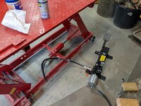
The air over pneumatic jack that I bought was pretty expensive but I went with it because it retained the option for pumping by foot when air wasn't available. At first the pump was relegated to sit on the floor but I found that to be a huge nuisance. I ended up building a carrier for the pump that slides into the end of the supports of the table. This position actually allows for better access to manually pump the jack enough to get it off the locking bar to lower the table without having to hook up air.

All and all I'm really happy with the modifications.

Argh... I'm having issues trying to attach a picture of the pump. Hopefully the link here works:
https://photos.app.goo.gl/fF9ayX2rmna46qzL6
 
To avoid these ads, REGISTER NOW!
Top Bottom