To avoid these ads, REGISTER NOW!

Illuminated light switch operation

brooktre

Well-known member
Joined
Oct 5, 2014
Messages
176
Location
Northeast Pennsylvania
I replaced about 15 illuminated light switches with new ones in a rental property. Some of the switches would not illuminate in the off position consistently. Although some switches worked, I replaced them all anyway.

I decided that I would use a few of the switches in my shop, but was unsure of which ones were working intermittently. To test the switches, I used a spare 3 prong plug and wired it as follows:
Black wire from plug to top switch connector
White wire from plug to test lamp (white side)
Ground wire from plug to switch ground
Black wire from bottom switch connector to test lamp (black side)

This did not work. Whether the switch was on or off, the light was on. Same result on several switches. I also verified that the plug I was using was wired correctly (black wire was hot). I later installed a couple of the switches replacing standard switches and they worked as designed.

How should I test these switches without installing them?
 
To avoid these ads, REGISTER NOW!

Dustball

Well-known member
Joined
Jun 25, 2011
Messages
2,081
Location
Hudson, WI
Power should enter the bottom terminal of the switch and the load should be on the top terminal.

72519d1477681247-wiring-illuminated-light-switch-img_7994.jpg
 

American Locomotive

Well-known member
Joined
Jan 8, 2017
Messages
11,002
Location
Rhode Island
Lighted switches typically have a neon bulb in parallel with the switch contacts. This means when the switch is turned on, the neon bulb gets both power contacts shorted out, and should not light.

I do not see how it would be possible for the bulb to light with the switch in the on position unless the switch was bad and wouldn't turn on.

The other thing I could think of would be that maybe the neon bulb was capacitively coupling to ground, but I'm not sure how likely that would be.
 

Innovate1

Well-known member
Joined
Jul 28, 2014
Messages
4,291
Location
Illinois near St. Louis, Missouri
This did not work. Whether the switch was on or off, the light was on.

Which light was on - the test light used as a load or the light in the switch? It seems unlikely that the switch light could be on if the switch was in the on position and the load light was on. Any that I have installed didn't have any markings for load and line side so I think the light was in parallel with the switch contacts. It runs a very small current through the load when the switch is off and that illuminates the switch.

The switch that dustball posted must be different. Perhaps they run the small current to ground although that would only be able to illuminate the switch when it was on - backwards of how they usually work. I suppose you could apply hot wire to each of the switch terminals one at a time with the switch off and ground connected and see if the switch lights. Seems strange they would do that to a ground rather than requiring a neutral connection. Others will probably chime in to enlighten us all.
 

Innovate1

Well-known member
Joined
Jul 28, 2014
Messages
4,291
Location
Illinois near St. Louis, Missouri
From what I have read illuminated switches may have issues with LED bulb loads. The load bulb may dimly glow when it is supposed to be off and/or the switch may light dimly. Would be interesting to know if the design of the illuminated switches has changed to work better with LED bulbs.
 

Terry D

Well-known member
Joined
Mar 25, 2015
Messages
2,202
Location
St. Louis, MO.
If you are using a LED lamp and its possible to replace it with a incandescent, try that to see if the problem goes away
 

Dustball

Well-known member
Joined
Jun 25, 2011
Messages
2,081
Location
Hudson, WI
I have an LED bulb on a dedicated illuminated switch in my kitchen and the illumination works just fine.
 
To avoid these ads, REGISTER NOW!
OP
B

brooktre

Well-known member
Joined
Oct 5, 2014
Messages
176
Location
Northeast Pennsylvania
Some clarifications.
- The light that was always on was the test lamp, which is an incandescent bulb.
- The light inside of the switch never lit. It is supposed to light when the switch is off and turns off when the switch is on.
- These switches are not marked to show which should be line and which should be load. I tried the switching the hot wire, but there is no difference if it is on the top or bottom terminal.
- Again, I installed the same switches in a box for a bathroom light and it worked as designed (bulb inside switch is on when bathroom light is off and bulb inside switch is off when bathroom light is turned on).

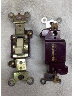
Pictures of switches (these are probably from the 70s based on building construction which was about 1974).
 

Attachments

  • IMG_1162x.jpg
    IMG_1162x.jpg
    107.8 KB · Views: 38

Innovate1

Well-known member
Joined
Jul 28, 2014
Messages
4,291
Location
Illinois near St. Louis, Missouri
I didn't see American Locomotives response until after I posted so am editing my post. As they noted if the test lamp was always on there was a problem with the test. Since the switch works in the end location it should be possible to figure out the problem with the test.
 
Last edited:
OP
B

brooktre

Well-known member
Joined
Oct 5, 2014
Messages
176
Location
Northeast Pennsylvania
It's probably too new for it to be a mercury switch, but did you hold it upright for the test?

Anton - your suggestion worked and I guess that there is a mercury switch inside. The switches are labeled "top", which I didn't really think about because you would normally mount them so that the embossed ON on the switch would be oriented correctly.

I was able to quickly check all of the switches on the bench and found 5 that didn't work correctly. The switch bulb on these would light intermittently when in the off position as opposed to being continuously on.

Thanks to everyone again for your help and suggestions. I'm not well versed in electrical, but these connections (black, white and ground) are pretty basic. I checked connections multiple times and it just didn't make sense.
 

theoldwizard1

Well-known member
Joined
Feb 22, 2011
Messages
43,227
Location
SE MI
Lighted switches typically have a neon bulb in parallel with the switch contacts. This means when the switch is turned on, the neon bulb gets both power contacts shorted out, and should not light.
In electrical speak, when the switch is in the on position, the voltage drop between the two terminal is zero.

When the switch is in the off position, the neon bulb (and possibly a series resistor) is actually providing a "sneak" path to the load. The bulb is such high resistance, that the amount of current allowed flow (mA or less) is not enough to "power up" the load.
 
To avoid these ads, REGISTER NOW!
Top Bottom