To avoid these ads, REGISTER NOW!

In-Floor Circuit Length Deviation

CBR9Seadoo

Well-known member
Joined
Sep 22, 2009
Messages
52
I am drawing out my in-floor configuration and am wondering if there is a general guideline on how close in length each circuit should be to each other?

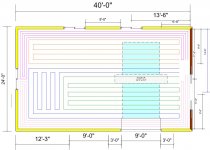
My planned garage is 24x40 and I am planning 5 Circuits. Right now there lengths are 217, 209, 220, 213, 213. I have attached the drawing.


Thanks, Tim
 

Attachments

  • InFloor.jpg
    InFloor.jpg
    109.4 KB · Views: 65
To avoid these ads, REGISTER NOW!

Notch1988

Well-known member
Joined
Feb 20, 2006
Messages
527
Location
Fort Saskatchewan, AB, Canada
Sorry dude, but no good. You've got two circuits doing all your perimeter... they're going to come back way way way way colder than the inside circuits. You want to try to balance the return temps, I wouldn't concentrate so much on equal lengths.
 
Last edited:

tdkkart

Well-known member
Joined
Jun 17, 2006
Messages
6,887
Location
Eastern Iowa
Correct, the 2 circuits you have running the outer edges will have way more heat load on them than the middle circuits.

Divide the building into quarters, then run one circuit per section. If you do it right, the lenghts will come out very close, and each circuit will have very close to the same amount of exterior wall.

Don't get too wrapped up in equal lengths, they should be reasonably close, but your number above are probably way closer than 99% of the installations that are done. If you have a good manifold system you can tweat the flow rates if needed to even up the temps.
 
OP
C

CBR9Seadoo

Well-known member
Joined
Sep 22, 2009
Messages
52
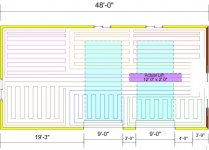
Ok, here is a new drawing. I have put two different layout on this one drawing. Also, when looking at the drawing. My building has 3 exterior walls. The dark wall on the right is actually the wall from the building that I am attaching this to.

So, is the top layout or the bottom better or do I need to go back to the drawing board.
 

Attachments

  • In_Floor_b.jpg
    In_Floor_b.jpg
    104.6 KB · Views: 29

egads74

Well-known member
Joined
Sep 1, 2008
Messages
87
looks like the bend is too small on the quicker turns where you double circuit in area.

Would it be better to work in to center of circuit area and back out for that 1 fifth area.

Have you determined where break lines area in cement and attempted to minimize tube in that area?
 
Last edited:

autoxbrian

Well-known member
Joined
Jul 3, 2008
Messages
93
Location
Mid-Ohio
Tim - Couple suggestions after speaking with multiple designers and suppliers, first it was a consensus that all loops should be within 10% of each other, ideally 5%. So assuming your average of around 210'/loop, that would give you a cushion of 21' or 10.5' ideally. Your largest spread is 11' so I think you are in GOOD shape on that front.

Aside from that, I am not sure why you are putting in so many bends and causing all the issues that you are. Here is what I have learned from multiple sources, and I know at least from my system design and efficiency works well.

The largest amount of heat should combat the largest heat loss areas, i.e. exterior walls, doors, windows. Therefore the largest amount of heat (where the supply lines FIRST leave your manifold) should combat this, as there is the largest amount of heat/energy in them at that point. So the design I added below was a QUICK not to scale use of MS Paint (can't you tell?) but it puts the LARGEST amount of heat to the exterior walls ASAP, rather than traveling through the middle of the room, loosing some of its heat/energy, then finding its way to the exterior walls. Each loop makes its first 'pass' of any distance close to the exterior walls to combat the loss, then as it snakes its way closer to the middle of the room, it needs less heat/energy since the 'coldest' part of the slab will 99% of the time be the exterior edges radiating in. I would recommend the exterior runs being 6" on center, then opening up to 12" on center once all 5 loops have run against an exterior wall first. (Again the attached jpg is NOT to scale; I was at work and just wanted a visual representation of the idea). The other thing you will notice... MANY LESS Bends/curves, for 2 reasons, ease of installation, and less corners/bends will allow easier fluid flow, with a bit less pressure/head loss. Just a suggestion, after LOTS of research all across the country, then doing our 1800sq ft garage (L shaped, oh joy) myself.
infloor.JPG
 
To avoid these ads, REGISTER NOW!
OP
C

CBR9Seadoo

Well-known member
Joined
Sep 22, 2009
Messages
52
Thanks, for the info.

I have posted a new drawing in another post. Taking into consideration what people have been saying.
 

autoxbrian

Well-known member
Joined
Jul 3, 2008
Messages
93
Location
Mid-Ohio
The drawing on your original post on this thread is closer to that idea, minus running the PRIMARY (first) runs of each loop to the exterior walls first, which I still feel is a major point to take into consideration.
 

sneezer41

Well-known member
Joined
Oct 8, 2007
Messages
407
Location
People's Republic of Mass
Consider running a second manifold on the other side of the room, so you do not have so many returns running together. Or maybe running them the short way.

While you are getting good advice, unless you are laying around on the floor naked, I don't think you will notice small differences in slab temp.
 

autoxbrian

Well-known member
Joined
Jul 3, 2008
Messages
93
Location
Mid-Ohio
sneezer - saw a few of your other posts, can you comment on the design thoughts here? Do you agree each line should run against the exterior wall to combat heat/loss first, then coil towards inside areas? Thanks, for Tim, and my own knowledge base.
 
OP
C

CBR9Seadoo

Well-known member
Joined
Sep 22, 2009
Messages
52
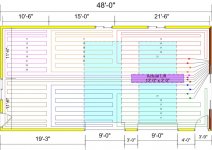
Ok, so if this is my current drawing. I should take and move my supply lines from the center of the building to the outside edges as fast as possible.

Here is my current drawing.
 

Attachments

  • In_Floor_b.jpg
    In_Floor_b.jpg
    122.1 KB · Views: 16

autoxbrian

Well-known member
Joined
Jul 3, 2008
Messages
93
Location
Mid-Ohio
Can I ask why you have each loop in a small block/square pattern with a million different bends? I guess to me, in my mind, that seems like extra work, and as another poster said, IF one loop were to not function, you'd have a HUGE loss in one area, where my suggestion of design has EACH LOOP running around the perimeter edge rather than a small grouping. I guess I'm curious as to your reasoning/research to do so.
 
OP
C

CBR9Seadoo

Well-known member
Joined
Sep 22, 2009
Messages
52
Can I ask why you have each loop in a small block/square pattern with a million different bends? I guess to me, in my mind, that seems like extra work, and as another poster said, IF one loop were to not function, you'd have a HUGE loss in one area, where my suggestion of design has EACH LOOP running around the perimeter edge rather than a small grouping. I guess I'm curious as to your reasoning/research to do so.

I am trying to equalize the amout of tubing per loop that touches the exterior walls. So that no one loop is taking on the all the cold from these MN winters.

Also, look at post #2 in here?
 
Last edited:

sneezer41

Well-known member
Joined
Oct 8, 2007
Messages
407
Location
People's Republic of Mass
I think you are overthinking it

If the place is insulated well, you will not notice.

When designing a house, you run the output along the outside wall first, if you can.

It is really a detail.

If you have enough output to heat the space, and insulation on the perimeter, the floor will be within a few degrees no matter where you are. Concrete is a lousy insulator, so how could a spot 1 foot away be 20 degrees cooler[unless there is no insulation]
 
To avoid these ads, REGISTER NOW!
Top Bottom