To avoid these ads, REGISTER NOW!

Inexpensive way to get amp draw?

brass89

Well-known member
Joined
Sep 15, 2014
Messages
240
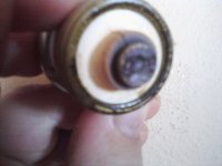
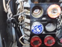
Hi all, I'm currently having some electrical issues in the house from the kitchen circuit. It's a 20a circuit connected to an old screw in style fuse box (only 6 circuits total). Something is causing excessive loading, I've been getting a 'fishtank' smell from the fuse box (inside main) and there's been some crackling and popping. The fuse itself is a screw in style 'mini breaker' with a push button reset on it and gets really hot to the touch within minutes of plugging it in. As far as I know, the only appliance 'on' was the refrigerator.

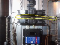
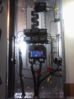
Needless to say it's now out of the fusebox killing the kitchen circuit and tomorrow I'm planning to get a real breaker box (200a service since that's what's coming off the main pole). The fridge may be the culprit, or the old wiring (fabric type woven insulation, def planning to upgrade to romex). Or the old electric box. Currently the more active circuits are all on the same leg so that can't be helping matters with an overheat issue.

Without just replacing everything blindly, I'd like to be able to check the amp draw on various appliances or potentially the wires themselves to find the culprit of the overload situation. Problem is, all I have are plug in circuit testers (for proper wire connections, open grnd, reversed hot etc) and a fluke multimeter (no amp clamp). I'd love to get another fluke, but can't really afford it.

Is there a cheaper alternative that works decent? Would something like a 'kill-a-watt' energy monitor work? (includes volts/amps/usage) I think it only works for connected appliances though since it plugs into the outlet and the appliance plugs into it. Doubt it can test wiring like an amp clamp does.

I'm not opposed to hf although it wouldn't be my first choice since I don't have one local and shipping takes awhile. Would a meter like this one work ok? http://www.amazon.com/dp/B00IRLJTGA/?tag=atomicindus08-20

I know it too has to be shipped but I have prime so it'd be 2 day shipping. I'm just not familiar with other brands than fluke. This wouldn't have to be industrial grade for professional use, just a 'band aid' meter for the moment to solve this problem with a decent amount of accuracy. Obviously some low end meters are just plain junk and not worth pulling off the shelf to read the packaging.

Thanks in advance for suggestions.
 
To avoid these ads, REGISTER NOW!

CNGsaves

Well-known member
Joined
Sep 26, 2012
Messages
13,233
Location
KS and OK
+1 on amp clamp. It's what my A/C repair guy used to check draw for condensor outside.

Post up pics of your panel and wiring so the sparky guru's can tell how expediently you need to swap out panel !! Lots of fires this past week with cold weather, most certainly due to overloaded wiring / space heaters, etc. Be safe and don't use appliances that are dangerous.
 

CoopVA

Well-known member
Joined
Jan 20, 2014
Messages
2,144
Location
Virginia
It's difficult to give an accurate diagnosis without actually looking at what you have, but my opinion is that the fuse/ mini breaker has gone bad. The wiring is probably in need of replacing also. Wiring that is as old as you describe is probably no longer safe... The clue here is that just the load of a refrigerator is overheating a 20 amp circuit. Cracking and popping at the breaker is indicative of a bad breaker...


Sent from my iPad using Tapatalk
 
Last edited:

Eriehunter

Well-known member
Joined
Mar 14, 2014
Messages
189
I have an Ideal multi meter it has an amp clamp, it does resistance continuity and voltage IIRC it was about $100 and it is very accurate. I got it at Home Depot or Lowes. The Fluke meters are nice but generally expensive.
 

Milton Shaw

Well-known member
Joined
Feb 11, 2011
Messages
4,840
Look at wire insulation around the house to make sure you don't have damage from rodents (rats, mice, squirels). They love the taste of insulation and I have seen a lot of damage from them. This could be the reason you are overheating at the box. Lucky is has not caused a fire so far.
 

toplessHO

Well-known member
Joined
Oct 20, 2014
Messages
14,055
Location
central florida
just be careful. Messing with hot wires can get you seriously or fatally wounded.
I suspect the fuse holder is tired and arcing inside or at the connection to the wiring.
Fuses are actually better than circuit breakers in breaking under a fault load.Do you have an IR gun you can scan wiring and connections?
You can screw in smaller and larger fuses to see where the circuit is amp wise
but dont leave the oversize one in,use for testing breifly
 
OP
B

brass89

Well-known member
Joined
Sep 15, 2014
Messages
240
I'll try to get some pics posted. The circuit/wiring is grounded, I've tested the plugs with a plugin style tester that tests for present ground etc. I screwed the fuse in as far as it would go until it was tight but yes there's lots of evidence of arcing on the contact both inside the box and on the tip of the fuse (which is why I pulled it completely). I can also hear buzzing and see blue arcing behind it at the contact bar.

The way the electric is set up, there's a service panel on the pole with a meter and a 200a main breaker inside of a panel, so I have a way to safely kill all the power prior to the fuse box (and will check with my voltmeter to ensure the large feed wires are dead). Then it comes into the fuse box inside - a connecticut electric panel with a 60amp main. I suppose you could call it that, the main is essentially a plastic faced 'brick' with spades on the back (inside) and a d ring style pull handle. Instead of switching it, you grab the d ring and pull it out completely. Part of the wiring (to the living room) appears to have been replaced with romex, the wiring to the kitchen is the older paper insulated in the wall. Had planned to replace the wire with romex and reroute it.

All circuits are 20amp (there's only 5 of them). Originally the previous owner had 30a fuses installed likely due to an issue with frequently overloading the 20's however I don't believe the wiring is rated at 30a which is why I went to all 20's. I'd rather have a breaker/fuse blow than stay on until a wire successfully ignites somewhere between the outlet and fuse box.
 
OP
B

brass89

Well-known member
Joined
Sep 15, 2014
Messages
240
Sorry for the poor image quality, my phone's camera isn't the best. The first pic is of the burnt contact on the offending fuse. The second is a shot of the fuse slots on the panel (the upper left missing fuse is the corresponding receptacle). There's a fuse also missing middle right but there's no circuit connected there and the connections don't look much better in that abandoned opening. The third pic is an overall of the fuse panel complete with sloppy wiring.
 

Attachments

  • P11-19-14_11-59.jpg
    P11-19-14_11-59.jpg
    90.6 KB · Views: 86
  • P11-19-14_12-01 (1).jpg
    P11-19-14_12-01 (1).jpg
    134.8 KB · Views: 100
  • P11-19-14_12-01.jpg
    P11-19-14_12-01.jpg
    128.8 KB · Views: 99

abk241

Well-known member
Joined
Aug 22, 2014
Messages
310
Location
SF Bay Area, California
Start by replacing that fuse/breaker in pic 1 with a brand new one.
If you still get all the same problems you will have to get hold of a clamp-on ammeter.
If pricing of new ammeter is outside your budgit...try searching here in the classifieds, craigslist, or fleabay (alwaysmy last resort).
To help isolate the problem turn off all appliances on that circuit and turn them on one at a time while checking current draw.
 
OP
B

brass89

Well-known member
Joined
Sep 15, 2014
Messages
240
I'm about to head to the store.. it's not ideal, but there's an Eaton 200a breaker box with a few 20a and a 30a breaker combo kit for around $115 at a big box hardware store nearby. I know it's their home line, only 10yr warranty.. not crazy about the alum bus bar but that's what's installed now. Also planning on 12-2 uf wire in the event I need to re run new wire under the crawlspace from box to the outlets. They say it's rated for direct ground contact/burial without conduit and better for less than perfect dry conditions. Rather than try and fish new wire through all the walls, considering the electrical box is at one end and the kitchen is at the opposite end.
 
OP
B

brass89

Well-known member
Joined
Sep 15, 2014
Messages
240
Thanks to everyone's advice so far. Couple of questions (not sure if it should be a new thread or not). I picked up a 200a eaton service panel to replace my old crappy fuse box.

Is this considered a 'service entrance' panel? It's the only panel inside the home, where the power comes inside at so I want to say yes. The reason for asking is because the meter box on the pole also has a door on it with a 200a breaker inside of it. Installing this new panel, I'll have line power to pole, through the meter, through a 200a breaker, large service cables (4o or whatever they are) into the 200a breaker on the new indoor panel (that all the house circuits connect to). My question relates to a copper ground bonding strap and depending what this panel's role is depends on whether or not to attach it. (attached for service panel, un attached for secondary tier panel).

Another question, the product I purchased was a 'kit' of sorts. Came with panel, 5 20a breakers and 1 30a breaker. I was assuming each 20a breaker would supply 1 household circuit. These look like a regular sized breaker with 2 smaller individually operating 20a switches. Almost like 2 independent slim breakers in one. There are also 2 terminals per breaker. Does this mean 2 20a circuits can be installed per breaker? The 30a is different in that it looks like a double unit with 2 full size switches physically bridged. Both 20a and 30a say 2 pole on them. Maybe I'm used to seeing older single pole breakers.
 

wyliesdiesels

Well-known member
Joined
Aug 14, 2012
Messages
20,031
Location
Modesto, CA
The new panel youre putting in your house is a subpanel. Neutral bar needs to be isolated/insulated from the EGC bar and the panel which means the bonding strap should NOT be used!

This is because u have a disconnect ahead of it. The way it works is 3 wires to the first disconnect with bonded neutral bar. After that its 4-wire.

Exception: Pre 2008 code allowed 3-wire feeders so u need to check. However, since youre upgrading the panel, code requires it to be done to current code which means 4-wire. Depending on what kind of feeder wire u have this fould be easy or hard. Take some pics, post em and tell us what kind of wire u got feeding the house
 

LS6 Tommy

Well-known member
Joined
Dec 27, 2013
Messages
26,162
Location
Northern NJ
Good thing to update. Those Edison base minibreakers are for non-inductive loads, so they do that quite frequently when you use them to feed something like your refrigerator.

Tommy
 
Last edited:
OP
B

brass89

Well-known member
Joined
Sep 15, 2014
Messages
240
The current fuse panel (splitting main power to 20a circuits) inside is a different design than the replacement I picked up but from what I can tell the common and ground bus bars are separated. All the bare copper grounds from the 20a lines are on one bus with a solid aluminum ground cable (bare) that runs out to a ground rod.

The 200a existing panel outside on the power pole with the meter has it's own ground and a 200a main breaker, if I flip that it kills the house and this panel (which I plan to flip before switching out panels). I'm assuming by 4 wire at a subpanel you're referring to the 2 hot (120v), 1 common and 1 isolated ground.

The new 200a replacement panel has a bridge strap running behind the backpan connecting the ground and common buses so that can be removed and the buses are already isolated from the panel with insulating stand offs.

As for the leads coming into the indoor panel from the outside meter main, they're 2awg copper strand. 3 wires, 2 120v and 1 common connected to the common bus.

Not sure I grasp the importance of a fridge being an inductive load (had to look it up). Obviously I'm not an electrician but understand some electrical basics and have done specific electrical work but not general house wiring. After doing some reading though, most everyone agrees that a fridge should be on it's own circuit. The way it's been since I've been here (around 12yrs +) the entire kitchen is on 1 20a circuit. Consisting of 6 outlets. Essentially the kitchen being all one circuit (aside from ceiling light which is on a separate circuit) all the appliances are sharing that 20a circuit. Fridge, microwave, toaster oven, coffee pot. Not all run at the same time and due to the issue of popping the edison fuse/mini breaker special attention has been paid to run only one major thing at a time. If the toaster oven is on, don't run the microwave - if the microwave is running, don't plug in a roaster pan or crock pot. Real pita. The issues of popping the minibreaker have gotten progressively worse which I'm sure is a combination of issues.

I did however pick up some 12-2 uf wire (not romex) and now that a new panel will offer more connections I can run a new dedicated circuit under the crawl space and up to the outlet for the fridge. Also picked up some additional outlets to replace the aging ones and got the 20a rated vs the 15a so I can replace the fridge outlet with a brand new 20a fed by it's own 12-2 wire (with ground) on it's own 20a circuit. How it's lasted this long mostly without issue I'm not sure. That's why I didn't know there was an issue to begin with.

Also if I understand correctly a 2 pole breaker with individual breaker switches is typically used for a 3 wire setup. Can be used for 2 separate 2 wire circuits with the exception that if one or the other on the same 2 pole breaker trips, they both trip. Something about adding a bridge pin to make the switches work together for safety reasons when shutting down involving a 3 wire shared common setup (which I'm not doing). Probably best for my situation to just place 1 circuit per breaker and leave 1 pole unused treating them like a single pole breaker.
 
To avoid these ads, REGISTER NOW!

wyliesdiesels

Well-known member
Joined
Aug 14, 2012
Messages
20,031
Location
Modesto, CA
I didnt read your last post word for word, pretty long...however

U spoke of isolated ground and thats incorrect. Ground bar shouldnt be isolated from the panel, the neutral or what youre calling common, SHOULD BE isolated.

It sounds like te 2 bars ur speaking of are actually both neutral bars. Leave these connected and leave the bar to panel bonding strap disconnected. U then need to buy one or 2 ground bar kits.

As far as 4 wire feeder goes, do u have 4 wires coming from the pole. The wire going to the ground rods(s) is something entirely different, its called a GEC(grounding electrode conductor). Grounding electrodes are for lightning and ground wires/EGCs are for fault current paths...The GEC connects to the ground bar as does the EGCs from the feeder an branch circuits...

Post up some pics of your panel.

And if pattenp were here, he could post a handy diagram of everything im explaining!

A double pole breaker for a MWBC(multiwire branch circuit- 120v/240v) needs to have a handle tie. A double pole breaker for a 240v load ideally should have common trip capabilities(internally) or if not then a handle tie so if one leg faults, the other leg is tripped via the handle tie...
 
Last edited:
OP
B

brass89

Well-known member
Joined
Sep 15, 2014
Messages
240
Sorry, took awhile to get power back on. The windows in this room aren't ideal for daylight and working in the closet so most of it was in the dark.

There's a main backpan with the spades for the breakers and the main 200a breaker in the center. Main breaker accepts the 2 120v hot wires coming in. There's two buses, one with a thicker screw down connector than the other (accepts the common). Those are the 3 wires coming from the main service panel off the pole. The other bus is similar except has a smaller screw down connector (for ground wire). Originally the panel a flat insulated aluminum bar behind the back pan that connected both buses together. According to the install instructions (they number labeled it for reference), that strap was supposed to be removed if used as a sub panel.
 
OP
B

brass89

Well-known member
Joined
Sep 15, 2014
Messages
240
Here's some pics. When I dug into the old fuse panel, I removed the main disconnect which was a plastic housing. Inside were two 60amp cartridge fuses. That's where a lot of the issue was, I'm surprised it didn't blow. It should have. Instead, the circuits I'd been having trouble with - that corresponding fuse was burnt to hell and the cardboard was toast. Big pile of ash inside the main disconnect plug box.

If you look at the first pic, you can see the fuse on the left looks intact and the contacts on the ends are still brass colored. It's solid. The one on the right is ashy grey and the contact clips that hold the fuse are loose and wobbly.
 

Attachments

  • P11-20-14_12-45.jpg
    P11-20-14_12-45.jpg
    99.3 KB · Views: 37
  • P11-20-14_12-46.jpg
    P11-20-14_12-46.jpg
    73.1 KB · Views: 35
  • P11-20-14_12-46 (1).jpg
    P11-20-14_12-46 (1).jpg
    131.6 KB · Views: 33
OP
B

brass89

Well-known member
Joined
Sep 15, 2014
Messages
240
Here's a pic of the new setup. Not really sure what's 'code' and what isn't, did my best to keep things separate.

The only thing I'm not sure about, the wires are a bit short for the box I put in. In order to get one of the common wires to the bus, I took a shortcut between 2 sets of breakers. Not sure if that's a no no. The wire is insulated and about 2" from the hot spades. Where it goes across I left an empty row of breakers (it's not mashed tight between two adjoining rows of breakers).
The second photo has a yellow highlight around the common taking a shortcut to make it more visible.

Not sure if it matters which way the ground (bare) wires go routing wise, but because they're bare I made sure to loop up or down and around the perimeter of the back pan. Not going across it any place.

Unfortunately because of the limited in-wall wire I had to work with, I did end up adding some wire lengths via wire nuts (said they're rated for 12ga wire and 600amps). Not sure how else people solve the issue of short wires without running all new wire.

All wires go through clamps at the knock outs. So far so good, everything feels nice and cool to the touch after a few hours of running. Compared to the old fuse setup where the fuses got too hot to touch in a matter of minutes.
 

Attachments

  • common between breakers.jpg
    common between breakers.jpg
    101.9 KB · Views: 42
  • P11-20-14_17-51.jpg
    P11-20-14_17-51.jpg
    118.1 KB · Views: 46
OP
B

brass89

Well-known member
Joined
Sep 15, 2014
Messages
240
Worst case, if it's wrong practice or unsafe having that common wire running across the breakers (between them) I can always cut another length of wire and go down and around to get to the bus bar.
 

wyliesdiesels

Well-known member
Joined
Aug 14, 2012
Messages
20,031
Location
Modesto, CA
I guess u didnt read my last post.....

Both of those bars should be neutral bars. Those neutrals should definitely NOT be cutting across the buss like that. Use a wire nut and short piece of wire to extend them.

How many feeder wires do u have coming into this panel from the main panel on the pole??
 
OP
B

brass89

Well-known member
Joined
Sep 15, 2014
Messages
240
I did read your last post, i'm just confused.

The Eaton install manual says "Grounding and Bonding -
A. For service entrance applications, attach bonding strap to neutral bar. Torque neutral wire screws to 35in-lbs.
B. For second tier panels fed from the service entrance panel, DO NOT attach bonding strap"

The emphasis was theirs, not mine. There is an outdoor meter box with breaker box in one on the pole. Power co has access to the meter and above, I have access to the lower portion and inside is a 200a breaker. From there, three 2 gauge copper leads come to the home and up into the panel I just installed. Leading me to believe the one on the pole is the service entrance and the one inside with all my various breakers and circuits is a secondary panel or sub panel.

Not trying to annoy, I'm not familiar with all the terminology. If by feeder you mean any/all fat 2 gauge wires or just the hots. Three total, two hot 120v, one neutral.

Thanks for the heads up, that's not a biggy to extend the wire and loop it around. Someone before me used whatever they had around to extend a wire and used white to extend a black hot. I did think to fix that (technically it worked, just confusing mixing colors).
 

wyliesdiesels

Well-known member
Joined
Aug 14, 2012
Messages
20,031
Location
Modesto, CA
Ok so in #18 i explained all this.

Yes the feeder is the wire between the 2 panels...

Your house panel IS a subpanel so normally, it should have unbonded/isolated neutral. However, it sounds like u have a 3-wire feeder(2 hots, neutral and NO EGC/ground). Pre2008 code allowed this. Since this is the case, then your house subpanel should actually have a bonded neutral bar(s).

2008 and newer code requires 4-wire feeder. Code also requires the feeder wiring to be updated since your changing the panel out, so technically u should run either a new feeder or run an EGC IF you dont have a bundled cable assembly.

A 4-wire feeder IS safer. However, in your case, it wont make much of a difference seeing as your service is on a pole. If it were in a separate building with parrallel metal pathways between the 2 buildings, i would say u have to upgrade the feeder!
 
Last edited:
OP
B

brass89

Well-known member
Joined
Sep 15, 2014
Messages
240
Sorry again for the confusion. Spent awhile on google trying to find diagrams to try and get a clearer picture. Also went back through the install manual that came with the panel and it's copyrighted 2006. Shame on Eaton as far as I'm concerned, it's been 8 going on 9yrs since that manual was written - at the very least, almost 7yrs since the code update. I can appreciate that products may sit on a shelf, but that's just lazy.

Apparently as you said, as it stands now I have an older setup. 3 wire feed. I didn't install the main service box on the pole (assuming power co did?) since it contains their meter. So I can't say with certainty how it's wired. I'll double check again but pretty certain it's 3 wire feed. No incoming ground from the main.

So what is my solution? I've seen different setups on panel boxes, mine is real basic. 2 hots (on a pan for the breakers to lock into), 1 neutral bus (isolated) and 1 ground bus. Use the included strap to bond neutral bus to ground bus in the subpanel (along with ground wire to ground rod). Or try and lay some sort of ground cable between main and sub panel to create the 4th lead? Not sure what size, if it needs to be insulated.

You're right, there are no metal pathways (pipes etc) between the home and pole. It's a mobile if that makes any difference (which might explain the main being on the pole instead of directly inside as with a house).

I don't mean to be hesitant, was always under the impression wires were meant to be kept separate with the exception of ground. With the update, it sounds like more and more is getting doubled up and looped together (egc ground AND ground to earth AND tied in with the neutral). I'm also not an electrical whiz which is why I ask so many questions, I do worry about safety and trying to do it right. Thanks for all your help so far.
 
OP
B

brass89

Well-known member
Joined
Sep 15, 2014
Messages
240
In a previous post you suggested the service box had 2 neutral bars and I needed a ground bus. Both the item description at lowes and the instructions referenced a ground bus and neutral bus, 1 each.

Just trying to clarify what I got since I mentioned the strap it came with. There's 2 parts it refers to, one being a strap running from bus to bus behind the back pan, the other is a raised copper 90* with a hex screw that screws into the bus and attaches to the case (bond I assume). Also the buses aren't the same size. The neutral is a bit longer and has a larger lug for the bigger service wire. The lug on the ground bar is bigger than the small connections for the individual 12-2 wires, but not large enough for a service wire. Sort of in between sizes.
 

wyliesdiesels

Well-known member
Joined
Aug 14, 2012
Messages
20,031
Location
Modesto, CA
Ok so looking at your panel pic in #24 i see 2 bars which are insulated from the panel enclosure. U said theres a bar tying these 2 together. Also u said theres a bonding strip. This is all indicative of neutral bars. Neutral bars come insulated. Ground bars are never insulated and are screwed directly to the panel. The bonding strip is to bond the neutral bars to the enclosure and ground! Also, ground bars are seldom ever sold with the panel. They have to be purchased separately.

What makes this all confusing is that u have an old 3-wire feeder. In this case, your neutral bars SHOULD be bonded UNLESS u decide to upgrade to a 4-wire feeder.....

I will see if i can find a diagram for u....
 
OP
B

brass89

Well-known member
Joined
Sep 15, 2014
Messages
240
I know what you're saying and I've seen panels with 2 neutral bars (so installer doesn't have to extend wires to left side breakers all the way around to the right or vice versa).

I found it odd that both are isolated - and that both are unequal in size, both in length and main wire lugs at the end - one being big enough for service cable, the other too small. There's plastic 'feet' on either end of both buses that the mounting screws go through to attach to the panel. I think for the ground, since it's physically isolated via the mounting screws, that's why they included the copper 90* that screws directly to the enclosure. In essence making it a ground bus that's in contact with the frame.

Here's pics to try and clarify, did the best I could with flashlight (it's dim in my closet) and cell phone. A pic of the two different buses and the strap.
 

Attachments

  • ground bus.jpg
    ground bus.jpg
    98.2 KB · Views: 34
  • ground neutral strap.jpg
    ground neutral strap.jpg
    80.6 KB · Views: 30
  • neutral bus.jpg
    neutral bus.jpg
    92.1 KB · Views: 25

Alchymist

Well-known member
Joined
Mar 1, 2009
Messages
4,423
Location
Central PA
Over the years different manufacturers made different styles of neutral- grounding bar setups. Since they have no way of knowing if the panel will be a main or a sub panel, many chose to isolate both bars so they could be used as neutrals and a ground bar added, or remove the strap between bars and use one for neutral and bond the other to the box for ground. One bar has a large hole for the incoming neutral, and the other has a smaller hole, (but still larger than the rest of the locations on that bar) for a ground wire to a ground rod. Several bonding mechanisms were used - bonding screw thru bar into panel, copper grounding lug to panel, etc.

There are 3 ways the panel can be set up -

1) main panel, first disconnect - neutral and ground bars bonded, and bonded to panel, with ground wire to ground rod. This is a 3 wire feed.

2) Sub panel within the same structure - neutral and ground bars separate, neutral isolated from panel, ground bar tied to panel, no ground rod. (This requires a 4 wire feed).

3) Sub panel in detached structure - neutral and ground bars separate, neutral isolated from panel, ground bar tied to panel, ground rod required. . (This also requires a 4 wire feed, and a main breaker for disconnect if the number of breakers exceed six).

Overall there can be any number of bars - there can be one neutral bar or two, one ground bar or two, for example.

All this applies mainly to 240V single phase residential.
 
OP
B

brass89

Well-known member
Joined
Sep 15, 2014
Messages
240
Ok. My setup would be #3 since there's a main/disconnect on the pole. Separate structure (if you want to call a pole a structure). Currently neutral is isolated from ground. Ground is bonded to panel enclosure only and main ground lug is attached to ground wire to ground rod. Only difference being the 4th egc wire missing (which sounds like pre 2008 setup).

Seems like another case of misinformation. The original electric something wasn't right about it and there were power co cables going from pole to pole over top of the mobile. They removed the wire and said that couldn't be like that. Required a new pole and everything be setup. A new pole was set, new box/meter/200a breaker attached for around $1800 (had to buy the pole etc). I was away when this happened, a family member was here and it was a pro install and inspected by the power co and passed. Since this was after 2008, you'd think they would have mentioned the 4 wire lead requirement.

It becomes further confusing when there's legit reasoning behind changing codes (for safety measures) - up until 2008, 3 wire leads were approved. All the sudden in 2008, they decided 4 wire was required. Yet older installs are still approved and not required to be updated. Not very logical that 3 wire lead is unsafe, but only if done after 2008. Done in 2007, magically it's safe again. These are minor grounding differences. Yet even if a house is old and has original 2 wire outlets those are legit too and they're not grounded at all. Go figure.

A case was discussed elsewhere why the 4 wire is safer, but in all fairness the guy who got shocked had done so by a diy conversion of a 2 phase to 3 phase homegrown motor on some piece of equipment, using the neutral for a 3rd phase and then decided to ground to his metal workbench. A bit extreme and a lot of purposeful misguided tampering that led to that situation. Wasn't like he plugged in a t.v. to a grounded socket and got shocked. Hard to blame the electrical setup if deciding to run electrical items in water with ground and neutral tied together. It's asking for trouble.
 

Alchymist

Well-known member
Joined
Mar 1, 2009
Messages
4,423
Location
Central PA
The existing installs (installed prior to code changes) are "grandfathered" in. Not required to be changed unless other upgrades/additions being done. In this case a lot depends on what the local inspector wants to see.
 

Alchymist

Well-known member
Joined
Mar 1, 2009
Messages
4,423
Location
Central PA
Ok. My setup would be #3 since there's a main/disconnect on the pole. Separate structure (if you want to call a pole a structure). Currently neutral is isolated from ground. Ground is bonded to panel enclosure only and main ground lug is attached to ground wire to ground rod. Only difference being the 4th egc wire missing (which sounds like pre 2008 setup).

Is there a ground rod at the disconnect on the pole, and a neutral/ground bond? If so, there should be 4 wires to the panel. If not, then your panel should have a neutral/ground bond and a ground rod.

Bottom line is that there should be only ONE place where the neutral and ground are bonded together. Sounds like a question for your local AHJ.
 
OP
B

brass89

Well-known member
Joined
Sep 15, 2014
Messages
240
I'll have to check the box on the pole, I think there's customer access to the lower portion (where the first 200amp service breaker is). I wasn't around when it got installed so I can't say for sure. There is a ground rod at the pole yes. That was part of the inspection during their install. The sub panel inside the home is also grounded to a ground rod. Far as I know the only missing link is the egc from main service to subpanel.

Not really sure what 'code' is around here I think it's supposed to be the same everywhere but how well it's enforced is beyond me. I live in a real rural area and there's lots that flies around here that I doubt is code. While going to check the mailbox this evening, perfect example. My neighbors have an rv (motorhome) that's parked in their front yard. I have a feeling someone is living in it. The most recent addition was some sort of contraption in place of one of the sliding windows with a stove pipe coming out of it so apparently they've installed (and are running) a wood stove inside the rv. That's new. lol

Thanks again for all your help, I really do appreciate the advice and time you've taken to help clear things up for me.
 

wyliesdiesels

Well-known member
Joined
Aug 14, 2012
Messages
20,031
Location
Modesto, CA
Here u go. I found the diagram, that I said i would look for.

A pic is worth a thousand words, possibly more in this case since it takes so many words to describe it! :lol:
 

Attachments

  • image.jpg
    image.jpg
    87.8 KB · Views: 37
Last edited:

BFBOB

Well-known member
Joined
Sep 20, 2011
Messages
5,073
Check around for a used clamp-on.

I picked up an Amprobe clamp-on ammeter at agarage sale for $5 just because. Haven't had occasion to use it yet, but as you've found out, ya never know.
 
To avoid these ads, REGISTER NOW!
Top Bottom