To avoid these ads, REGISTER NOW!

(Ingersoll Rand) - Where should this pipe go?

mawrick

Well-known member
Joined
Nov 1, 2012
Messages
102
Location
Norway
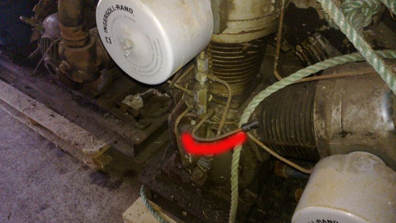
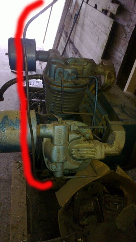
Any of you guys know how these pipes are supposed to be connected - and to what ? (I presume they have something todo with taking the pressure of the cylinders when the compressor stops??), as it sits today they are just going straight into the air.

kompressor2.jpg


kompressor.jpg


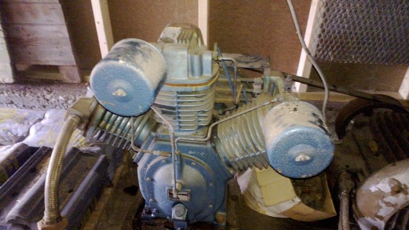
Overview of one of the compressors:

12100022.jpg


Would I be correct thinking this pipe should hook up to a pressure switch unloader valve ?.
 
To avoid these ads, REGISTER NOW!

Provincial

Well-known member
Joined
Sep 21, 2011
Messages
6,874
Location
Near Salem, OR
It looks like the valve that controls the cycling of the compressor when it is used in a system that shares compressors into one manifold. The valve is adjustable to the point that it can cause the compressor to run continuously, if that is desired. In some industrial applications, the cycle time of the compressor may only have the compressor "off" for a short while, and using this valve will allow it to run continuously, but unloaded, thereby avoiding the power surges involved in repeated starts, and therefore a reduced electric bill.
 
OP
M

mawrick

Well-known member
Joined
Nov 1, 2012
Messages
102
Location
Norway
Ok, I suspect the two compressors I have have been used together so that might be what these pipes have been then.

Any idea if I can just plug off that pipe (want to use only one of them as a stand alone).

Also how does these compressors bleed off the air when it stops ? (should there be a line going to an unloader valve ?).
 

4x4gearhead

Well-known member
Joined
Oct 4, 2010
Messages
1,820
Location
New Hampshire
If you look on the top of the cylinder there is a blowoff valve that lets the air in the pump out so that when the compressor fires up its not fighting residual pressure. That appears to be on top of the diagonal facing head.
 
OP
M

mawrick

Well-known member
Joined
Nov 1, 2012
Messages
102
Location
Norway
If you look on the top of the cylinder there is a blowoff valve that lets the air in the pump out so that when the compressor fires up its not fighting residual pressure. That appears to be on top of the diagonal facing head.

Ahh - I presume this is the one your refering too:

popoff3.jpg


Any idea if I could just plug off that pipe that have been used for "dual compressor" operation?.
 

GeneralDisorder

Well-known member
Joined
Sep 20, 2012
Messages
306
First picture I'm not totally sure on - that's not a setup that I've seen before. It looks like the line is coming off a shuttle valve of some sort. Possibly part of an unloader system of some kind

Second picture - that's the supply line for the head unloaders - used for pilot valve operation. It was disconnected from a pilot valve that was plumbed to tank pressure.

Last picture is the interstage pressure relief valve. It will blow if the discharge pressure from the first stage goes above it's set-point. This usually means there's a valve issue in the second stage and pressure is backing up in the intercooler.

GD
 
Last edited:
To avoid these ads, REGISTER NOW!
OP
M

mawrick

Well-known member
Joined
Nov 1, 2012
Messages
102
Location
Norway
Ok - not sure what that pilot valve operation is, but any idea if that pipe can just be blocked off? (since I only want to use one compressor).

Also any way to check the pressure rating on that safety valve?.


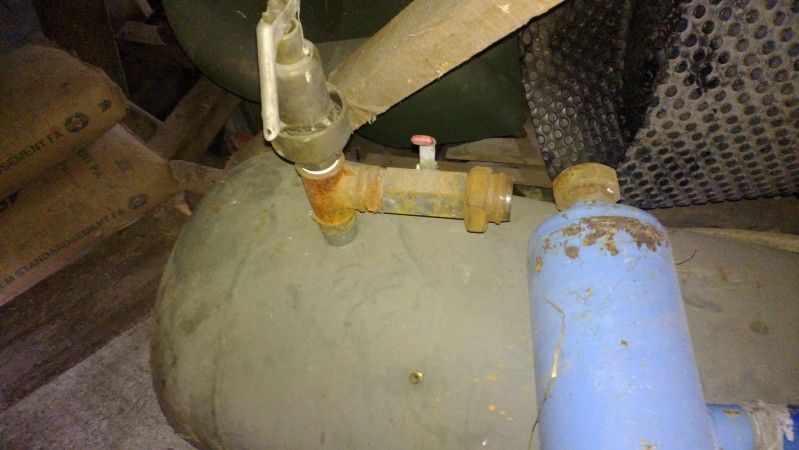
If you guys have any tips on what I need to get to hook it upto this tank:

12110003.jpg


12110004.jpg


12110006.jpg


(Don't mind the small silver valve - as that was just put there to plug of the hole as it stands now)...:)


What I guess I would need is a pressure switch to control start/stop of motor, and then hook up the braided line to the tank itself - but I guess I will have to get a non return valve for the tank as well.

(I'm thinking maybe there is one on the second picture - but not sure if that's it ).

The tank came with the compressors - but obviously some things are missing, as they have been part of a bigger system. Also came with a "dryer tower" - but don't think I'l set that one up).
 

GeneralDisorder

Well-known member
Joined
Sep 20, 2012
Messages
306
Pilot operation is really nice to have - it allows the compressor to "unload" and not make any air but continue to run. This way you don't have to cycle the motor on and off a whole bunch of times - which with those ~20 HP motors is not good for them. You just need a pilot valve plumbed to the tank and then to that line going to the intake unloaders.

You will need a tank check valve as these pumps have centrifugal unloaders that will dump the head pressure but you still have to prevent that pressure from getting out of the tank and back into the discharge line.

GD
 

Greatbear

Well-known member
Joined
Jan 17, 2008
Messages
1,702
Location
Columbia/Fulton, MD
That line is used for a continuous run unloader setup. These are used on gasoline engined compressors as well as larger electric units as a way of increasing duty cycle. I have a Dayton compressor that has an unloader, it is great for long sessions using the blast cabinet. It works by air pressure, sending pressure into the lines activates a piston to hold the intake valves on all the cylinders open, stopping the compressing action (the cylinders now breathe in and out of the intakes) while the pump still runs. This allows a gas engine to continue running, or in the case of electrics, the pump still runs, receiving cooling air from the flywheel fan. This is very useful for heavy continuous use.

The compressor setup needs a "pilot valve" that is preset to just below shut-off pressure, usually about 5 psi. This valve opens at the set pressure, sending air to the uloaders, when the tank pressure drops by about 10psi, the valve closes tank pressure and vents the unloader side to the atmosphere, releasing the pistons holing the intake valves open, resuming compressor function. Some 2-stage compressors have an interstage valve that opens with the unloaders, reliving pressure between the first and second stages (where the intercooler resides) to allow the second stage cylinder(s) to breathe freely when running unloaded.
 
OP
M

mawrick

Well-known member
Joined
Nov 1, 2012
Messages
102
Location
Norway
How would I go about using one of this compressors as a "normal" compressor then - where I will shut off the motor when tank reach a certan pressure?.

It got quite a big motors (about 25 HP) - but for my use these will have long pauses between each start - have quite a big tank as well.
 

Greatbear

Well-known member
Joined
Jan 17, 2008
Messages
1,702
Location
Columbia/Fulton, MD
How would I go about using one of this compressors as a "normal" compressor then - where I will shut off the motor when tank reach a certan pressure?.

Don't connect the continuous run unloader lines to anything. The unloaders only function when pressure is applied to them, when left open to the atmosphere the internal return springs release them and the compressor operates normally. Just use a typical head unloader setup with a check valve at the tank, and an unloading pressure switch or the centrifugal unloader build into the pump.
 
To avoid these ads, REGISTER NOW!
Top Bottom