Hello
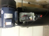
My first post here please excuse my jumping right into asking for help. I have been setting up my garage for a while and have run 50 amp service for my welder and 30 amp for my air compressor. I have just bought the magnetic starter to finish up my a/c install but am looking for some help as to how to hook it up.
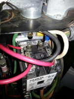
I had originally run a 30 amp line to my pressure switch and ran my 5 h.p. through the pressure switch also. After reading on this site I have concluded I need to install the mag starter it had one originally but I was told by a "buddy" I did not need it. I have 220 service up to the unit along with a functionilne pressure switch so I assume the install is pretty straight forward. I have attached 2 photos.
Thabks in advance
Jim S
Jim, here is a quick sketch of a wiring diagram for you and others.

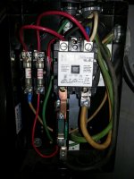
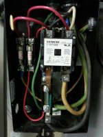
You have a IEC 3 phase starter and a 1 phase motor. IEC starters are balance sensitive on the overload relay portion. When you run the motor current through 2 poles only, you will have balance problems. The overload relay will nuisance trip on you because of the unbalance from zero current in the third overload heater. To correct this wire like the sketch shows, that is connect the power to L1 & L2, then connect the motor to T1 & T3. Then install a jumper from L2 to T3. This will route the L2 current to L3 pole and create a balanced condition in the overload relay section.
For the controls portion tap L1 for power and run to the pressure switch line terminal. From the motor terminal on the pressure switch run it back to the starter coil left terminal (located on the top of your starter).
Tap L2 for power and run to the overload relay NC (normally closed) terminal 95. From the overload relay NC (normally closed) terminal 96 run it back up to the coil right side terminal.
Thus wired the pressure switch will control the left side of the coil power and the overload relay will control the right side of the coil power. Both will need to be on (closed) to get the starter energized. If either one opens the starter will be turned off.
A few other suggestions.
It is a code requirement to have a disconnect at the motor starter location as shown, unless your supply breaker is within sight of the starter location and less than 25' away. A lever switch on the pressure switch is not adequate for the code when using the magnetic starter.
Mounting of the starter on the compressor is a high vibration location, and this can cause problems over time. Either mount the starter on the wall, or brace the enclosure top and bottom to reduce vibration on the sheet metal enclosure. The starter and it's enclosure will thank you if you mount it securely to minimize resonant vibrations. Otherwise it may crack the enclosure or cause the connections to loosen over time, causing problems for the starter and compressor.
For the overload setting, set it at the nameplate amps of the motor. If it trips at that setting, you can turn it up to the maximum value of the SFA (service factor amps) and no more, to provide proper overload protection for your motor. Keep the setting as low as possible for the best protection of the motor.
Using a magnetic starter will greatly extend the life of your pressure switch contacts, and give long reliable service when done correctly.
MTW
")