Next comes conduit. The generator is about 6-8 feet from the corner of the house. Right around the corner, on the end of the house, is the power meter. The easiest way to get to the meter area would be on the outside wall, but there is a downspout there and a fence post within an inch of the brick. Inside the house at that corner is the utility room with the breaker panel and the water heater. The inside wall covering (paneling) was removed when I wired in the portable generator. I had never replaced it cause I never felt that was a long-term, permanent solution. Also there are wiring problems at the breaker panel that needed to be fixed, so the wall where I need to run the generator wires is already open. Since I can't go around the outside of the corner I will go inside on the back wall of the house, then go through the end wall directly into the transfer switch. It will look better since there will be no conduit exposed on the end of the house except the existing feed from the ground up to the meter base.
This is the hole where the portable generator inlet box was located. I need to enlarge it for 1 1/4" conduit for the power wires. The marked circle is the size it needs to be. If you have ever used a hole saw you know you have to have a pilot bit in the center to keep it from "dancing" all around as you try to get it started. With that size hole in the center, a hole saw is useless.
But a wooden peg driven into the hole will give the pilot bit something to keep it centered.
And this is after I had started drilling:
The same hole from the inside:
This is after drilling through the brick and changing to a regular bi-metal saw for the wood. Three 2X4s together in that corner stud.
That will get the power wires from the generator into the wall. We will deal with going back through the wall into the ATS later. First, because it determines exactly where on the wall the ATS will mount, I will go through the wall for the new wires to feed the main panel.
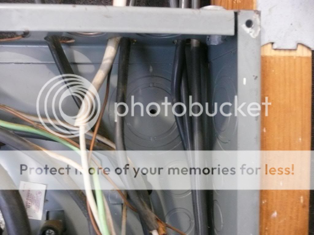
The existing wires from the meter base to the main breaker will have to be removed and discarded. The meter base and main panel are back to back on the left side of the panel (as viewed from inside). Notice there is no plastic bushing on the end of that 2" conduit to protect the wires from its sharp edges. That will be corrected on the new setup.
The ATS will be mounted to the left of the meter (as viewed from outside). The new wires will go into the ATS through a short rainproof hub. Then from the ATS they will come into the main panel through the opposite corner from where the existing wires are in the previous pic.
This is the new entry location. I have to get a hole through the outside brick lined up exactly with this knockout:
So I work from the inside out. First I drill a 1/4" hole in the center of the knockout. I held a shop vac under the drill bit to catch the chips.
Using that hole as a guide, I drill through the brick with a 1/4" masonry bit:
Above you can also see the knockout I will be using in the side of the meter base to connect to the ATS.
Using that hole as a guide for the hole saw, I drill through the brick:
That is a 2 1/2" hole, which turned out to not be big enough for the raintight hub to fit into. I later opened it up with a hammer and chisel.
Here you can see it is lined up perfectly with the knock out in the box inside:

I don't have pics for the next few steps. Next I removed the knockout from the side of the meter base and installed a raintight hub with a short threaded ****** connected to another raintight hub, the one to be connected to the ATS. I then held the ATS against that hub and marked it for drilling. The ATS is in a NEMA 3R enclosure. That means outdoor rated, weather proof. There are no knockouts on the box, so holes can be drilled or punched where ever they need to be, provided they clear the internal switch components. Speaking of the switch, it is best to remove it from the box while drilling or punching holes. Kohler warns several times to not get chips in the switch, and to only use a vacuum (NEVER compressed air) to remove chips if the switch is in place. Removing the switch solves that problem, and makes the box much lighter. With that hole drilled I was able to place the box on the wall where it will be mounted. After leveling it, I had a helper hold it in place while I went inside with an extended length Sharpie and marked the location for the hole in the back. This is an extended length Sharpie:
(Sharpie taped to a piece of 1/2" conduit)
After drilling that hole it was just a matter of measuring inside the box to determine where the other two holes could be. You just have to pick a place that clears the switch and lugs and is also accessible from inside the wall. Fortunately I had a full 16" stud space to work in. Once you determine where the holes will be, drill the brick from inside as before, then use that 1/4" hole to guide the hole saw from the outside. Then hold the box back on the wall and mark the other two holes. This is the result, three holes in the back of the box:
And three matching holes in the wall:
(I had already ran the conduit when I took the pic.) That little grey wire is the phone wire I will have to make sure it doesn't get pinched behind the box when mounting it. It is too short to go around the box.
This is the new conduit into the main panel:
And with the plastic bushing on the end. All the raintight connectors in the ATS have bushings built in, that is what the yellow plastic is on the other end of the conduit.
And the finished conduit in the wall:
On the outside wall. Still needs clamps.
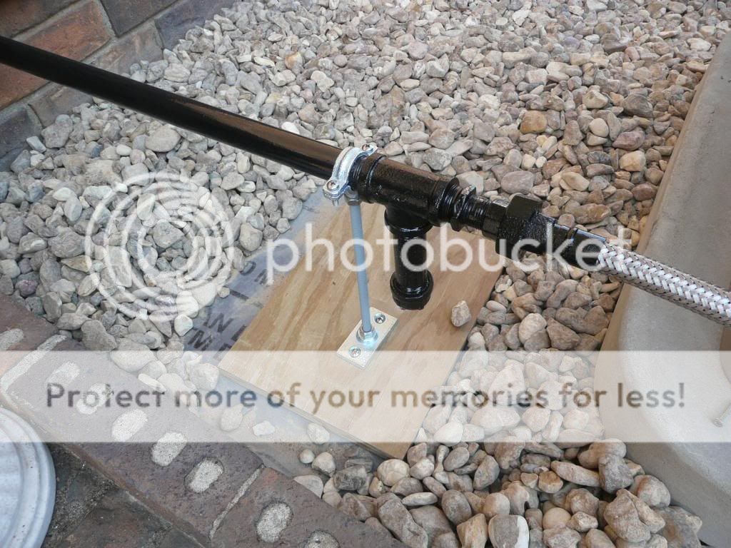
At the generator:
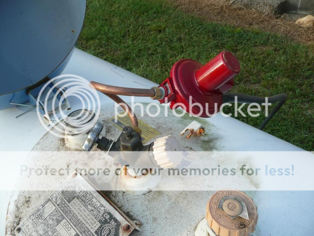
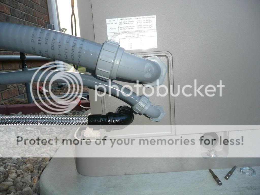
The generator connection panel:
I didn't get a pic of the switch mounted, I will post that tomorrow. As soon as I get the conduit mounted on the outside wall I will be ready to pull wire.
jp

")


 And thank goodness for the flex connection!
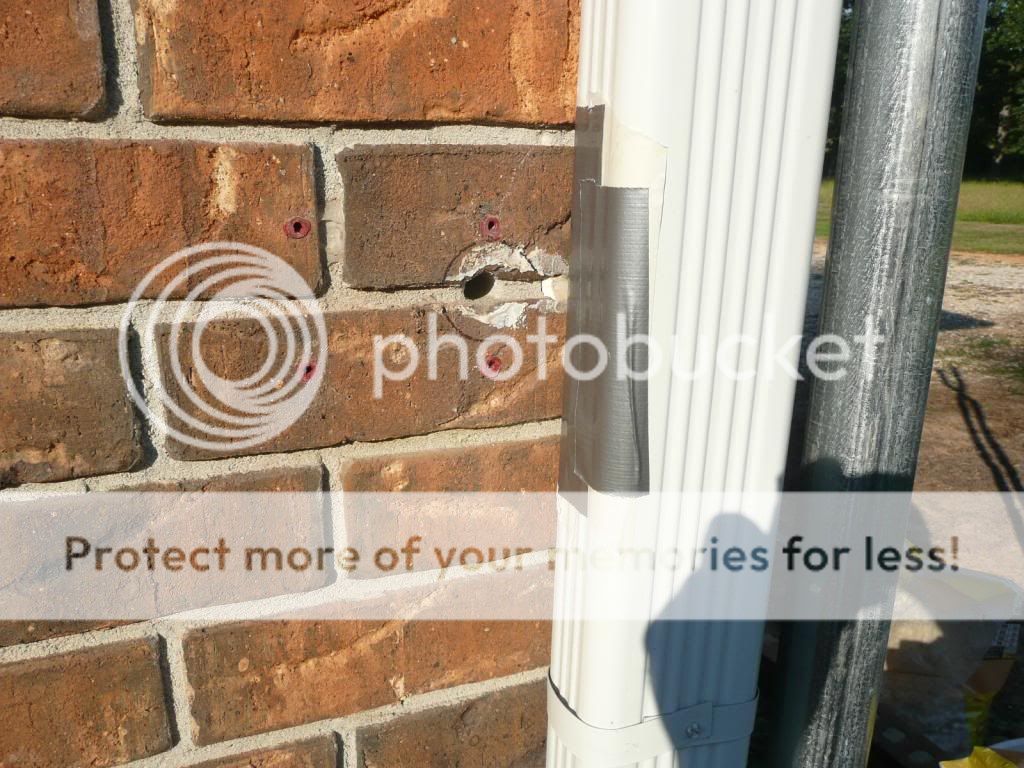


 Tons of disagreement. My understanding is that the neutral and ground should NOT be bonded in the generator. It came with a bonding strap installed. Kohler says it depends on the installation, and the generator will work properly either way. The way I understand it is, that since the neutral is not switched by the ATS, there should be only ONE neutral/ground bond, and that is at the first means of disconnect, in this case, the ATS. Bonding the neutral/ground in the generator would be the same as having them bonded in a subpanel. Correct me if I am wrong.