To avoid these ads, REGISTER NOW!

Installing A Switch on CM Bench Grinder

ckadams00

Well-known member
Joined
Sep 12, 2011
Messages
1,273
Location
Seattle, WA
Hi all - I'm sure this is a simple question for anyone with wiring knowledge but I don't want to screw it up and fry something and I haven't been able to get this figured out.

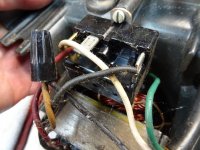
I want to install an on/off switch on this bench grinder - I just don't know what where to put it. Photo wires are as follows: ground/black/white on lower right are coming from the cord. Red/yellow/black on lower left are coming from the motor winding.

If I put the switch between the two black do i need to pigtail another wire to the starter relay? Any help is much appreciated!
 

Attachments

  • DSC03344.jpg
    DSC03344.jpg
    150.9 KB · Views: 62
Last edited:
To avoid these ads, REGISTER NOW!

ForceFed70

Well-known member
Joined
Apr 27, 2010
Messages
3,441
Location
BC, Canada
I assume your grinder starts as soon as you plug it in.

In that case, cut the black wire - connect both ends to the switch.
 
OP
C

ckadams00

Well-known member
Joined
Sep 12, 2011
Messages
1,273
Location
Seattle, WA
I assume your grinder starts as soon as you plug it in.

In that case, cut the black wire - connect both ends to the switch.

Got it, that's what I though but . . .plumbing mistakes I can clean up, electrical I prefer to ask.

Thank you!
 

6PTsocket

Well-known member
Joined
Mar 12, 2014
Messages
4,593
Is the motor wired to run without a switch now? If it is, cut the black wire and connect the two ends to the switch. I ssume the wires from the motor are presently connected and the grinder runs when you plug it in. It sounds like somebody had a switch go bad and instead of replacing it they wired the grinder to run when plugged in. When we say cut the black wire, you can also take it out of the wire nut and add another short piece at the wire nut so you have a little more length if you need it. Whoever bypassed the switch probably took that short wire out and threw it away and connected the black wire from the cord directly to the wire nut.

Sent from my SM-G900V using Tapatalk
 
To avoid these ads, REGISTER NOW!
OP
C

ckadams00

Well-known member
Joined
Sep 12, 2011
Messages
1,273
Location
Seattle, WA
Believe it or not this is a factory original CM - one of the few models they made without a on/off switch in the 60s. Can't understand why someone would make one without a switch - seems unsafe to me. Others have posted CM catalog photos that confirm they actually made some without switches.
 

CJ7VFR

Well-known member
Joined
Jan 13, 2015
Messages
2,939
Location
Central New Jersey
Believe it or not this is a factory original CM - one of the few models they made without a on/off switch in the 60s. Can't understand why someone would make one without a switch - seems unsafe to me. Others have posted CM catalog photos that confirm they actually made some without switches.

My dad has one of these old CM models without the switch.

In his owners manual for it, it says to plug the grinder into a receptacle that is powered by an ON/OFF wall switch. The example in his book shows the type of switch/receptacle combo you can buy at any big box store.

Maybe you can do that if you don't want to hack up the cord, and the receptacle you want to plug the grinder into is not too far away. In my dads case, the switch/receptacle combo is on the wall right behind and slightly to the left of the grinder in an easy to reach place.

On a side note, you might want to run a separate circuit for that grinder. I know that whenever my dad fired his up, any lights on that same circuit would dim down and then come back on as the grinder got up to speed!

Jim
 

6PTsocket

Well-known member
Joined
Mar 12, 2014
Messages
4,593
What does the front panel look like? Hopefully, there is room for a toggle switch. An external or cord switch really sounds awkward. You can get a 20amp switch that is pretty small. Just cut into the black cord wire. It is amazing how low the safety standards were back then. I have a 50s CM jointer on CM post stand. The drive belt is totally exposed and you can walk into it. Belt guard was an optional accessory. I have an old aluminum case B&D drill that had a 2 wire cord and nobody had even thought if double insulation back then. Post a picture of the front and what is behind it and let's see if we can get a switch in there. If a standard size won't fit, I am sure a mini with a high current rating will. They are only a couple of bucks for safety and convenience.

Sent from my SM-G900V using Tapatalk
 

EOC_Jason

Well-known member
Joined
Jun 25, 2012
Messages
11,388
Location
Bentonville, AR
I'm assuming when you said the black/white/green coming from the plug, that the black is the one going to the wire-nut with the yellow?

If so, I would take off the wirenut, add some spade connectors on each end of the wires, then connect those to any single-pole switch with the appropriate volt/amp rating, and you should be good to go.
 

6PTsocket

Well-known member
Joined
Mar 12, 2014
Messages
4,593
I'm assuming when you said the black/white/green coming from the plug, that the black is the one going to the wire-nut with the yellow?

If so, I would take off the wirenut, add some spade connectors on each end of the wires, then connect those to any single-pole switch with the appropriate volt/amp rating, and you should be good to go.
Or quick disconnects (fast-on connectors), which are the means of connection on many switches.

Sent from my SM-G900V using Tapatalk
 
To avoid these ads, REGISTER NOW!
Top Bottom