To avoid these ads, REGISTER NOW!

Installing new subpanel; do manufacturer instructions supercede code?

KRGaijin

Member
Joined
Apr 17, 2025
Messages
14
Hi all, I'm installing a new subpanel. The main panel is outdoors, this subpanel is indoors. Conduit is already installed (PVC, with one junction box between the panels).

The conduit situation is 4 separate PVC conduits running to the junction box (2x1 1/4 and 2x1"). The wires being run are the service wires and 12 circuits, 2 30A, five 20A and 5 15A. The wires have been upsized due to CCC and derating, so it's all 10 and 8 AWG for the circuits. PVC conduits range from 7 to 10 feet long.

Feeder wires and four of the 20A circuits have already been pulled. I have two conduits left, one with five 15A circuits, the other with two 30A and one 20A.

The manufacturer instructions for the subpanel seem to be oriented only towards installing next to an indoor main panel. My installation has an outdoor main panel, so I've had to upsize wires to make it code compliant. (Example, the instructions specifically call out 10 AWG for any 30-amp circuits, but due to CCC derating and ambient temperature derating, I need to use 8 AWG wire). So the manufacturer's instructions, while appropriate for an all-indoor install, are giving instructions that wouldn't be code compliant for an indoor install connecting to an outdoor panel. I assumed that the proper wire as per the code is the better choice and that's what I went with.

But when it comes to the ground wires I'm not sure here. I'd love to take advantage of 250.122(C), which says (in part) "A single equipment grounding conductor shall be permitted to be installed for multiple circuits that are installed in the same raceway, cable, trench, or cable tray." Especially in the conduit that's running five 15A circuits, that's 15 wires of 10 AWG white/black/green wire in a 1" conduit with three 90 degree bends. I'd LOVE to use a single 10 AWG ground wire, instead of five, that would drop my conduit fill down to 26.93% for a much less painful pull.

However, doing so would conflict with the manufacturer's installation instructions, which says that for each circuit you:
a) remove the hot wire from the breaker
b) remove the neutral from the neutral bus bar
c) remove the ground from the ground bus bar
d) connect the hot wire removed from the panel to the breaker in the subpanel
e) connect the neutral wire removed from the panel to the neutral bus bar in the subpanel
f) connect the ground wire removed from the panel to the ground bus bar in the subpanel

Based on those instructions, I assumed I had to run an individual ground wire for each circuit, hence my plan for 5 ground wires in the 5-circuit conduit. BUT:
a) the instructions are incomplete; for example it says "remove the hot wire from the breaker" but for a 240V breaker, there are two hot wires, and it doesn't specify that.
b) as aforementioned, they specify a range of 14-10 AWG for the circuits, but I have to use a minimum of 10GA for all these circuits.
c) No mention is made of the accommodations I've had to make for connecting to an outdoor panel.

So, after that long preamble, we get to the actual question: do I have to run individual ground wires in the conduit as the mfr instructions imply, or can I take advantage of the NEC rule stating one ground wire is sufficient for all circuits in that particular conduit? Am I bound to having to run individual grounds just because the (slightly imprecise) instructions say so?

(additional info: all the grounds coming into the main panel are bare copper wires, and they're all run in a big bunch up to the bus bar, so they're all basically commonly shared anyway. I don't think it'd be possible to isolate them and then trace them to find which goes with which circuit, which I am guessing would be the only benefit to running individual grounds to the sub. Is there some benefit to having the individual ground wires grounding to the sub first, considering that the main and sub are connected by a 6 AWG ground wire anyway?)

Thank you very much for any advice!
 
Last edited:
To avoid these ads, REGISTER NOW!

micromind

Well-known member
Joined
Sep 24, 2023
Messages
3,124
Location
Fernley, Nevada, about 30 miles east of Reno.
In my opinion, code always overrules manufacturers instructions.

110.3(B) Installation And Use. Listed or labeled equipment shall be installed and used in accordance with any instructions included in the listing or labeling.

This is usually interpreted to state that manufacturers instructions must be followed but the actual fact is that if the instructions are not part of the listing or labeling then they are advice, not requirement.

Personally, I think that 110.3(B) needs to disappear.
 
OP
K

KRGaijin

Member
Joined
Apr 17, 2025
Messages
14
I read about 1/3 of that but I think I understand the question. One ground sized for the largest circuit in the conduit is fine and can be shared with the other circuits.

Sorry for all the word vomit. I try to give all the info up front, but yeah, I don't blame those who don't read it all.

I understand the rule the same way you do, but... 110.3(B); I'm just asking if there's something I'm missing and any advantage to doing it the way they say?

The TL;DR is: if the manufacturer's instructions say to do things one way (run individual grounds in the conduit for every circuit), but the NEC code specifically allows a different way to accomplish the same thing easier, less expensive, etc, am I bound to follow the mfr's instructions?
 

sparky 1971

Well-known member
Joined
Oct 9, 2018
Messages
8,078
Location
Central Iowa
Sorry for all the word vomit. I try to give all the info up front, but yeah, I don't blame those who don't read it all.

I understand the rule the same way you do, but... 110.3(B); I'm just asking if there's something I'm missing and any advantage to doing it the way they say?

The TL;DR is: if the manufacturer's instructions say to do things one way (run individual grounds in the conduit for every circuit), but the NEC code specifically allows a different way to accomplish the same thing easier, less expensive, etc, am I bound to follow the mfr's instructions?
You would have a ground per circuit if it were Romex. I'm going to assume you are shoving THHN/THWN through the conduit. One ground is fine as long as it's sized for the largest circuit in the conduit. Nothing in the instructions say anything about a ground per circuit, just to remove the ground. Each circuit will have a ground, but one ground for all is fine.
 
OP
K

KRGaijin

Member
Joined
Apr 17, 2025
Messages
14
What brand/model of panel? What is your location?

Can't say I've seen a panel with wire gage instructions...
Southeast Texas.

It's a "smart" panel, an automatic transfer switch and subpanel all combined. For the purposes of the question I thought that was too many details (and yes I see the irony there!) Specific unit is this one.
 
OP
K

KRGaijin

Member
Joined
Apr 17, 2025
Messages
14
You would have a ground per circuit if it were Romex. I'm going to assume you are shoving THHN/THWN through the conduit. One ground is fine as long as it's sized for the largest circuit in the conduit.
Yes it's all THWN-2 wire.
 
OP
K

KRGaijin

Member
Joined
Apr 17, 2025
Messages
14
Also post a pic of the panel
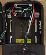
This is the panel at the current state of installation. I have run the aforementioned wires, #2 R/B/W and #6 G, and four 20A circuits #10 B/W/G, but they're just hanging loose at the moment. The only wires that are connected are the factory-wired red and black in the upper left, labeled L1/L2.
 

Attachments

  • IMG_20250417_191814497_HDR~2.jpg
    IMG_20250417_191814497_HDR~2.jpg
    208.4 KB · Views: 49
OP
K

KRGaijin

Member
Joined
Apr 17, 2025
Messages
14
In my opinion, code always overrules manufacturers instructions.
I would agree, I was just concerned that there might be some justification for the specifying of a ground per circuit for some reason I was unaware of. Or if there was any established hierarchy of (for example) "follow the NEC unless the manufacturer tells you to do something different". I didn't think there was, but I most definitely don't know everything, so I thought it'd be safer to ask around.

Thanks for your reply!
 
OP
K

KRGaijin

Member
Joined
Apr 17, 2025
Messages
14
Then use one ground per conduit. If you would have used EMT and a metallic junction box, you wouldn't need a ground at all.
Right. I just went PVC because we're fairly near the coast and we get ocean water dumped on us whenever a hurricane comes through, and I didn't want to face corrosion issues.

Also, thank you for all the lightning-quick replies, it's much appreciated!
 

PCustoms

Well-known member
Joined
Jul 23, 2011
Messages
23,692
Location
VT
In my opinion, code always overrules manufacturers instructions.

110.3(B) Installation And Use. Listed or labeled equipment shall be installed and used in accordance with any instructions included in the listing or labeling.

This is usually interpreted to state that manufacturers instructions must be followed but the actual fact is that if the instructions are not part of the listing or labeling then they are advice, not requirement.

Personally, I think that 110.3(B) needs to disappear.
What?

Code overrules inst instructions, but code clearly states follow inst instructions.


OP issue is his transfer switch (not a sub panel) has extraneously detailed instructions of how to move circuits over and it's tripping him up relative to the NEC
 

sparky 1971

Well-known member
Joined
Oct 9, 2018
Messages
8,078
Location
Central Iowa
What?

Code overrules inst instructions, but code clearly states follow inst instructions.


OP issue is his transfer switch (not a sub panel) has extraneously detailed instructions of how to move circuits over and it's tripping him up relative to the NEC
I think the instructions are printed using the assumption that romex will be pulled out of the old panel and moved to the new. They just say to remove the hot, neutral, and ground, then reconnect with nothing mentioned about a ground per circuit unless it appears after I lost interest and gave upl. If it were run in conduit to begin with with five hots, five (or three) neutrals, and one ground I doubt the manufacturer would expect four grounds to be added to the conduit run. Or add five if it were in EMT with no ground wire installed (the way I do it).
 
To avoid these ads, REGISTER NOW!

micromind

Well-known member
Joined
Sep 24, 2023
Messages
3,124
Location
Fernley, Nevada, about 30 miles east of Reno.
I would agree, I was just concerned that there might be some justification for the specifying of a ground per circuit for some reason I was unaware of. Or if there was any established hierarchy of (for example) "follow the NEC unless the manufacturer tells you to do something different". I didn't think there was, but I most definitely don't know everything, so I thought it'd be safer to ask around.

Thanks for your reply!

It depends on the listing. I seriously doubt that the listing calls for a separate ground for each circuit so the instructions are not required to be followed.
 

wyliesdiesels

Well-known member
Joined
Aug 14, 2012
Messages
20,129
Location
Modesto, CA
Im having a hard time following all that.

looking at the panel info, im not sure why they spec'd #2 when its a 100a breaker which only needs #3 cu

as for the branch circuits, it lists a max wire size of #10.... so #8 may be too big for the branch breakers.

how many CCC- current carrying conductors in each conduit? Im wondering if they didnt need to be oversized.... but keep in mind if you increase the size of the ungrounded conductors, the grounding conductors also have to be increased in size, proportionately....
 
Last edited:
OP
K

KRGaijin

Member
Joined
Apr 17, 2025
Messages
14
They just say to remove the hot, neutral, and ground, then reconnect with nothing mentioned about a ground per circuit unless it appears after I lost interest and gave up.
Thank you for making the effort to read the instructions, it's much appreciated!

So, it's possible that it's an interpretation error on my part? Re-reading it, you're correct that they don't explicitly say "one ground per circuit in the conduit". I had come away from the instructions with the sure thought that that's what they meant, but perhaps it isn't?

Here's the lines in question with exact wording:
5. Remove the GROUND wire of the selected circuit from the ground bus bar.
and
8. Connect the GROUND wire removed from the electrical panel to the ground bus bar on the Smart
Transfer Switch.
From that, and surrounding context where they use the identical phrasing about moving the hot and neutral, it gave me the strong impression that they were expecting the ground wire to be moved from the main panel bus over to the STS's bus the same way the B/W wires were. But now that you point it out, I can see that it's not making an explicit statement to include a separate ground wire for each circuit, it's just saying to connect it to the STS's busbar instead of the main panel's busbar, which clearly could be done through pigtailing off of the common ground wire in the same conduit the B/W wires are run in.

Thank you so much for helping me see how I had made an assumption that wasn't accurate, very helpful!
 
OP
K

KRGaijin

Member
Joined
Apr 17, 2025
Messages
14
It depends on the listing. I seriously doubt that the listing calls for a separate ground for each circuit so the instructions are not required to be followed.
As detailed in the answer above, I now believe you're right, it appears my interpretation of the instructions was more strict than what they actually say. Sorry for the confusion, and I appreciate all you folks' patience and assistance in helping me to see my error!
 
OP
K

KRGaijin

Member
Joined
Apr 17, 2025
Messages
14
Im having a hard time following all that.

looking at the panel info, im not sure why they spec'd #2 when its a 100a breaker which only needs #3 cu

as for the branch circuits, it lists a max wire size of #10.... so #8 may be too big for the branch breakers.

how many CCC- current carrying conductors in each conduit?
The #8 was necessary to maintain 30A through the CCC and ambient temp deratings. As requested, here's the layout:
All conduits affected by 9% ambient temperature derate
Conduit 1, PVC 40, 1 1/4": 3 CCCs, #2 R/B/W. Final ampacity >=100.
Conduit 2, PVC 40, 1 1/4": 8 CCCs, 2x #8 R/B/W (>=30A) and 1x #10 B/W (>=20A)
Conduit 3, PVC 40, 1": 10 CCCs, 5x B/W #10 (>=15A)
Conduit 4, PVC 40, 1": 8 CCCs, 4xB/W #10 (>=20A)

Now here's where I hope I haven't made another incorrect assumption: the Homeline 20A breaker PDF says:
homeline 20.jpg

The 30A breaker says the exact same thing. From that I took it to mean that it can accept one #8 wire of either copper or aluminum. My plan is to use this wiring for either 20A or 30A circuits as necessary; right now I plan on using only 15A and 20A circuits in the STS but I wanted to provide for future allowance of swapping out some 20A breakers for 30A circuits too. That's why I chose #8 wire for 30A ampacity, and am running an extra #8 red in the conduit alongside the regular B/W/G. My plan is to attach the (currently unused) #8 reds to the ground bus bars at each end.
 

mm08822

Well-known member
Joined
Jan 13, 2012
Messages
6,112
Location
NJ
The #8 was necessary to maintain 30A through the CCC and ambient temp deratings. As requested, here's the layout:
All conduits affected by 9% ambient temperature derate
Conduit 1, PVC 40, 1 1/4": 3 CCCs, #2 R/B/W. Final ampacity >=100.
Conduit 2, PVC 40, 1 1/4": 8 CCCs, 2x #8 R/B/W (>=30A) and 1x #10 B/W (>=20A)
Conduit 3, PVC 40, 1": 10 CCCs, 5x B/W #10 (>=15A)
Conduit 4, PVC 40, 1": 8 CCCs, 4xB/W #10 (>=20A)

Now here's where I hope I haven't made another incorrect assumption: the Homeline 20A breaker PDF says:
homeline 20.jpg

The 30A breaker says the exact same thing. From that I took it to mean that it can accept one #8 wire of either copper or aluminum. My plan is to use this wiring for either 20A or 30A circuits as necessary; right now I plan on using only 15A and 20A circuits in the STS but I wanted to provide for future allowance of swapping out some 20A breakers for 30A circuits too. That's why I chose #8 wire for 30A ampacity, and am running an extra #8 red in the conduit alongside the regular B/W/G. My plan is to attach the (currently unused) #8 reds to the ground bus bars at each end.
No. For all of the other details you are worried about, reds on a ground bar is pure blasphemy.
 

wyliesdiesels

Well-known member
Joined
Aug 14, 2012
Messages
20,129
Location
Modesto, CA
alright quite a bit to break down here.

starting with the main feeder, how did you come up with needing #2?

the 90° ampacity of #3 is 115a. if you derate for ambient 105-113° thats 87% of ampacity which brings you to 100a.

if you derated for the next highest ambient (114-122°) that would be 82% which brings you to 94a. there is no breaker that size so as long as the load is 94a or less you can put it on a 100a breaker. doubt your pulling 100a thru that TS

derating also for # of CCC in conduit doesnt apply here because you only have 3

and as said above, you cannot use a #8 red jacketed conductor on a ground bar or as an EGC. you cannot phase tape it either. only #4 and larger can be phase taped.
 

mm08822

Well-known member
Joined
Jan 13, 2012
Messages
6,112
Location
NJ
The manuals for the equipment state needing #2. Whoever wrote the manuals tried to dumb it down way too much and in doing so overlooked many viable NEC exceptions. Even which brand of cb's are acceptable was never mentioned until a footnote on the last page of the manual.
 
OP
K

KRGaijin

Member
Joined
Apr 17, 2025
Messages
14
No. For all of the other details you are worried about, reds on a ground bar is pure blasphemy.
Not pure reds. I was gonna use green tape to re-identify them and put a "SPARE" or "FUTURE EXPANSION" label on them.

I didn't see any specific instruction in the code about how to deal with spare wires. It's my understanding that I can't leave unterminated wires in the box, so I figured the ground bus bar was the most reasonable place to terminate them. Am I getting that wrong too?

Googling around it appears that most folks are saying that just wire-nutting the spare wires is sufficient to meet the code's requirements. I'd rather do that than make them look like grounds, if wire-nutting (or even just taping) is an appropriate way to ensure that the wire is considered terminated. I know in reality it will render the wires inert and safe, but common sense doesn't necessarily translate into code compliance. I thought terminating a conductor meant attaching it to something, like a breaker or a bus bar.
 
Last edited:
OP
K

KRGaijin

Member
Joined
Apr 17, 2025
Messages
14
The manuals for the equipment state needing #2. Whoever wrote the manuals tried to dumb it down way too much and in doing so overlooked many viable NEC exceptions. Even which brand of cb's are acceptable was never mentioned until a footnote on the last page of the manual.
Agreed entirely, that's why I'm struggling a bit with making their vaguery match up with the specifics of the code.

agreed. the manual is atrocious. definitely wasnt written by a true SME or electrician
Agreed again! It's more of a "quick start guide" than an actual list of instructions to follow.
 

mike93lx

ALLIANCE MEMBER
Joined
Dec 9, 2013
Messages
38,205
Location
Richmond, VA
Not pure reds. I was gonna use green tape to re-identify them and put a "SPARE" or "FUTURE EXPANSION" label on them.

I didn't see any specific instruction in the code about how to deal with spare wires. It's my understanding that I can't leave unterminated wires in the box, so I figured the ground bus bar was the most reasonable place to terminate them. Am I getting that wrong too?

Googling around it appears that most folks are saying that just wire-nutting the spare wires is sufficient to meet the code's requirements. I'd rather do that than make them look like grounds, if wire-nutting (or even just taping) is an appropriate way to ensure that the wire is considered terminated. I know in reality it will render the wires inert and safe, but common sense doesn't necessarily translate into code compliance. I thought terminating a conductor meant attaching it to something, like a breaker or a bus bar.
Having spare wires is OK but don't relabel them or land them on the ground bar. Cap and leave them aside
 

mm08822

Well-known member
Joined
Jan 13, 2012
Messages
6,112
Location
NJ
Not pure reds. I was gonna use green tape to re-identify them and put a "SPARE" or "FUTURE EXPANSION" label on them.

I didn't see any specific instruction in the code about how to deal with spare wires. It's my understanding that I can't leave unterminated wires in the box, so I figured the ground bus bar was the most reasonable place to terminate them. Am I getting that wrong too?

Googling around it appears that most folks are saying that just wire-nutting the spare wires is sufficient to meet the code's requirements. I'd rather do that than make them look like grounds, if wire-nutting (or even just taping) is an appropriate way to ensure that the wire is considered terminated. I know in reality it will render the wires inert and safe, but common sense doesn't necessarily translate into code compliance. I thought terminating a conductor meant attaching it to something, like a breaker or a bus bar.
Spares don't have to be terminated per code. All you want to do is make sure they don't errantly become energized at either end. So just tape the ends or use a wirenut.....then it's done...good enough.
 
OP
K

KRGaijin

Member
Joined
Apr 17, 2025
Messages
14
Appreciate all the responses and the spare wire issue is much clearer now. Thank you all for clearing that up!
 
To avoid these ads, REGISTER NOW!
Top Bottom