To avoid these ads, REGISTER NOW!

Isolating high voltage solder joints

1190R

Well-known member
Joined
Jul 31, 2014
Messages
252
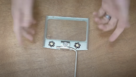
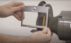
I'm replacing the old lighting on the back of my bench grinder eye shields with some 110v LED lights
I chose high voltage lights to take advantage of the existing wiring but am a little concerned about leaving the solder joints exposed
What is the best way to isolate the connections for both longevity and safety?

See lights here
 
To avoid these ads, REGISTER NOW!

PCustoms

Well-known member
Joined
Jul 23, 2011
Messages
22,384
Location
VT
Edit: damn those are tiny.

Seems a 12v solution would be a lot easier...
 
OP
1

1190R

Well-known member
Joined
Jul 31, 2014
Messages
252
Overkill I suppose, but I would 3d print an enclosure for the board, leaving the emitter exposed.
Agree
I'm planning on just epoxying them to the eye shield and was thinking of using something like silicone caulk or sealer for the electrical connection but figured I would post to see if there is a better solution

Yes, they are small but put out 10W!
 
To avoid these ads, REGISTER NOW!
OP
1

1190R

Well-known member
Joined
Jul 31, 2014
Messages
252
Are you are there's enough metal the to dissipate that much heat? If not they won't last long.
No but I guess I'll find out
I suppose I could expoxy to something that would allow some air flow underneath
I have a 10W LED lamp with a magnet base on another grinder that is fully enclosed and does not have overheating issues
 

walta

Well-known member
Joined
Jan 13, 2017
Messages
2,309
Location
Dutzow Missouri
Consider rethinking your choice of 120-volt chips.

I do not see an easy way to mount the chips in your link without a single hole. 100% of the chip must be covered to prevent any one from touching the chip and 170 Volt DC connections that are exposed. Covering the chip creates a new problem of cooling when you cover it you trap the heat the chip us generating if the temp gets too high you will destroy the chip. This chip will make one very bright little spot with lots of shadows that could be an advantage but not for a large work area. My guess is this chip board has an aluminum core to help dissipate heat. That type of circuit board is notoriously difficult to solder wires to.

I think you would be better off with a 12 or 24 VDC light tape so you have tons of light sources and almost no shadows they use small plug in power supplies to power the LEDS and are easy to solder.


Walta
 
OP
1

1190R

Well-known member
Joined
Jul 31, 2014
Messages
252
Consider rethinking your choice of 120-volt chips.

I do not see an easy way to mount the chips in your link without a single hole. 100% of the chip must be covered to prevent any one from touching the chip and 170 Volt DC connections that are exposed. Covering the chip creates a new problem of cooling when you cover it you trap the heat the chip us generating if the temp gets too high you will destroy the chip. This chip will make one very bright little spot with lots of shadows that could be an advantage but not for a large work area. My guess is this chip board has an aluminum core to help dissipate heat. That type of circuit board is notoriously difficult to solder wires to.

I think you would be better off with a 12 or 24 VDC light tape so you have tons of light sources and almost no shadows they use small plug in power supplies to power the LEDS and are easy to solder.


Walta
Good point on the possible 'spotlight' effect of single light

Will try first before gluing down and perhaps use 2 per eyeshield as seen in pic
 

BillK

Well-known member
Joined
Aug 24, 2006
Messages
9,305
Location
Beautiful Southern Maryland
Original most likely, if it was so equipped would have been a single work light hung off the back of the grinder on a flexible neck.
Probably so. I would just put an led bulb in it and be done. I cant imagine having lights in the shields considering how crudded up they get in normal use.
 

no704

Well-known member
Joined
Apr 27, 2016
Messages
5,207
Capcom tape. It’s translucent too might put a layer under and one over, not sure if you would even need to expose the leds.
 
OP
1

1190R

Well-known member
Joined
Jul 31, 2014
Messages
252
That just does not look like something I would want anywhere near the sparks and metal dust from a grinder ?? How were the original lights mounted ?
 

Attachments

  • 2.png
    2.png
    1 MB · Views: 26
  • 1.png
    1.png
    1.8 MB · Views: 29
OP
1

1190R

Well-known member
Joined
Jul 31, 2014
Messages
252
Probably so. I would just put an led bulb in it and be done. I cant imagine having lights in the shields considering how crudded up they get in normal use.
If I could find a bright LED bulb that would fit I would go that route
 

whateg01

Well-known member
Joined
Mar 13, 2006
Messages
11,211
Location
doo dah, kansas, usa
I've never seen a setup quite like that. So many different directions a guy could go. There are some bright automotive led bulb replacements. I might be tempted to see if that housing could be modified to use one of those just to retain the original look. But then again, I do stupid stuff like that.
 
OP
1

1190R

Well-known member
Joined
Jul 31, 2014
Messages
252
I've never seen a setup quite like that. So many different directions a guy could go. There are some bright automotive led bulb replacements. I might be tempted to see if that housing could be modified to use one of those just to retain the original look. But then again, I do stupid stuff like that.
https://www.ebay.com/itm/196431580324

https://www.ebay.com/itm/305177938026

https://www.ebay.com/itm/276389920315

https://www.mscdirect.com/product/d...-TsIjNetuoDDXeNCnyRoCZw4QAvD_BwE&gclsrc=aw.ds

Yeah, I'm leaning toward the LED replacement option

And yes, car turn signal bulbs have a similar base

Unfortunately I need 110v
 

whateg01

Well-known member
Joined
Mar 13, 2006
Messages
11,211
Location
doo dah, kansas, usa
You could probably use the existing wiring and insert a regulator somewhere inline. Or if you know how much the lights draw, add a resistor to drop the voltage.
 

lund

Well-known member
Joined
Nov 2, 2019
Messages
761
Location
Michigan
Those lights are pretty small LEDs. If run off of AC they are probably being rectified and voltage dropped somehow at the LED anyway. You also say "high voltage" but 120V AC is not exactly high voltage. Only modest insulation is needed. Soldering with heat-shrink tubes covering the splice should be fine even with modest vibration. The real issue is 120V circuits are usually 15 A and that is way high for something light duty and it can generate a good spark if the wires/insulation are damaged as could happen in a snafu situation. I would go a low voltage power supply.

I put a socket plug with a switch integrated below my grinder and buffer pedestal and LED lights are plugged into the socket along with the grinder. I use the integrated plug+switch to cut power to the grinder and lights when done and the grinder switch for temp on/off when working. The socket also allows plugging in other stuff nearby and comes in handy.
 
To avoid these ads, REGISTER NOW!
Top Bottom