To avoid these ads, REGISTER NOW!

j-pole antenna thread

NUTTSGT

Super Moderator
Staff member
Joined
Sep 14, 2009
Messages
50,862
Location
Northern Central Ohio
I know J-pole antennas have been talked about many times before and I've asked about them. I'm hoping to be making one in the next few weeks.

Maybe we can get a collection of "who" used "what" plans with links, pictures of your J-pole antenna and how/where you mounted it. Let's see if we can make another great GJ informative thread. Thanks.


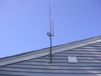
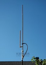
In case you're unfamilar with a J-pole antenna, I've attached a random picture from the 'net for reference.
 

Attachments

  • j pole.jpg
    j pole.jpg
    36.3 KB · Views: 646
To avoid these ads, REGISTER NOW!

Davefr

Well-known member
Joined
Jan 7, 2010
Messages
11,815
Location
OR
I made one based on some advice here at GJ. My goal was to extend the range of a wireless weather station.

It worked out very well and I doubled the signal strength.

Here's the formula I used and some images:

http://www.m0ukd.com/calculators/slim-jim-and-j-pole-calculator/

I had to start my adding an external connection for the antenna at the receiver end:

P1050011.jpg


P1050012.jpg


P1050013.jpg
 

CitadelBlue

Well-known member
Joined
Aug 1, 2009
Messages
710
Location
Northern VA
Because I had to look it up ......
The J-pole antenna, also called the Zepp' antenna (short for Zeppelin), was first invented by the Germans for use in their lighter-than-air balloons.[1] Trailed behind the airship, it consisted of a single element, one half wavelength long radiator with a quarter wave parallel feedline tuning stub. This was modified into the J-pole configuration by at least 1943[2] and became popular with amateur radio operators because it is effective and relatively simple to build.
https://en.wikipedia.org/wiki/J-pole_antenna
 
OP
N

NUTTSGT

Super Moderator
Staff member
Joined
Sep 14, 2009
Messages
50,862
Location
Northern Central Ohio
Thank you guys so far that have posted up. Nimrag, that link provides me with an idea of how to mount my future antenna.
 

Vegaman_Dan

Well-known member
Joined
Jun 1, 2012
Messages
2,453
Location
Pacific, WA
I've built a couple of these in copper pipe and they have no right in working at all. It's too easy, simple, and- well, they shouldn't work as good as they do. :)

I made sure to paint mine black if only to make sure copper thieves don't recognize it and swipe it. I moved and left it behind at the previous house so I need to make a new one.
 

ctfjr

Well-known member
Joined
Oct 30, 2011
Messages
167
Location
Basketball Capitol of the World
I made one based on some advice here at GJ. My goal was to extend the range of a wireless weather station.

It worked out very well and I doubled the signal strength.

Here's the formula I used and some images:

http://www.m0ukd.com/calculators/slim-jim-and-j-pole-calculator/

I had to start my adding an external connection for the antenna at the receiver end:


P1050013.jpg


Just a couple of notes on the coax connection here. You should seal the end of that coax from the weather. The product Coax Seal is like a thick tape and works well. If water gets down into the braid it will wick well into the cable and your signal losses from the cable will go up, a lot. Likewise, if you are using this for VHF or above (> 150mhz) the coax will have its own significant losses - the longer the cable the more the loss, the smaller diameter the cable the more the loss.
 

lilredex

Well-known member
Joined
Apr 29, 2006
Messages
5,949
Location
Toronto
I made one based on some advice here at GJ. My goal was to extend the range of a wireless weather station.

It worked out very well and I doubled the signal strength.

Here's the formula I used and some images:

http://www.m0ukd.com/calculators/slim-jim-and-j-pole-calculator/

I had to start my adding an external connection for the antenna at the receiver end:


P1050013.jpg

It may work better if you get more heat on those solder connections, they look very "cold" and probably not as conductive as they could be.
 

KEH

Well-known member
Joined
Jan 31, 2010
Messages
5,142
You can make one from TV twin lead antenna wire. I don't remember the details, but the insulation on the wire is cut off at one end and the 2 wired soldered together. On one side the wire is cut leaving a short gap. I don't remember how far down from the top. At the bottom the 2 wires are joined to a coax connector. The whole thing can be put inside plastic pipe to protect against the weather. It's cheap and thieves aren't tempted to steal it. Plastic pipe can be u clamped to a post,

KEH
 

JohnnieMo

Well-known member
Joined
Nov 25, 2014
Messages
1,175
Location
Calgary, Alberta
We used to just use a chunk of twin lead and solder one end together. We would then install them inside an electrical conduit. They worked okay. I found better luck out of a 1/4 wave 'coat hanger' with a ground plane. We would stick it in the attic out of the elements. Great coverage.

Wow its been a long time since I talked antennas!!

VE6DUR

Sent from my Passport
 

Macrosill

Well-known member
Joined
Mar 21, 2015
Messages
51
Location
Long Island, NY
I made the exact one the OP posted. It has been up for a few months now. Currently it is tasked with my 2m APRS system but also gets used as a general dual band when needed.

NG2S
 

Radio Ron w4ron

Well-known member
Joined
Jan 23, 2013
Messages
867
Location
Radio Heaven (near Charlotte NC)
What frequencies do these j antennas collect? FM? AM?


Well first off AM and FM aren't frequencies, they're modes of operation.
Most J poles are made for VHF and above as one for HF would be very large.

I've used them in the past, several twin lead models, had one mad to
be rolled up and be easily transported.

Like someone said I found that 2 meter and 70cm ground planes made
with brazing rod and a SO-239 worked best, I still have a couple of each
in my attic.

LLAP
 

KEH

Well-known member
Joined
Jan 31, 2010
Messages
5,142
I haven't looked up the formulas and used them recently, but antennas work best when cut to the proper length for a specific frequency, much more for transmitting than for receiving. Almost any length of wire placed in a high place and connected to the receiver with coaxial cable will improve reception. Since commercial FM radio stations use a fairly wide range of frequencies the antenna has to be a compromise as to measurements, but as I said, precise measurements are not all that critical for reception. The radio station's transmitting antenna is built to proper measurements.

FM stations operate with line of sight transmissions which is why transmitting towers are tall. In other words, the transmit antenna and receiving antenna should "see" each other. Therefore, receiving radios work better when they are in a high location. Commercial stations also have very powerful transmitters which reaches out to more people. Leaves on trees also can degrade the signal.

Short simple suggestion for anyone with poor reception is to take a portable radio and try reception out in the attic of the house. If no joy, get a TV antenna mast, fasten a FM receiver antenna bought from an electronics supply house to the mast, and erect it outside beside the building with the radio in it. Antenna should be as high as reasonably possible and certainly above the roof line.

KEH
 

LS6 Tommy

Well-known member
Joined
Dec 27, 2013
Messages
26,162
Location
Northern NJ
Ignorant question here. Can one of these style antennas be used on an "export" CB (modified 10 meter) like my Connex 4300-400?

Tommy
 

KEH

Well-known member
Joined
Jan 31, 2010
Messages
5,142
Sure, just has to be cut to length for the frequency that is being used. You will have to do a little research for proper formulas.

KEH
 
To avoid these ads, REGISTER NOW!
OP
N

NUTTSGT

Super Moderator
Staff member
Joined
Sep 14, 2009
Messages
50,862
Location
Northern Central Ohio
This is what I have come up with so far and tried it out this afternoon. I used dimensions found in one of the links above.

http://www.hamuniverse.com/jpole.html

The long section is 81", the short section is 27" I believe and the gap is about 2 1/2" per the formula.


I used a thread adapter and screwed it into a piece of black pipe and stuck it temporarily in the ground. I used some coax, not sure of it's exact name and attached one end for the back of the receiver.


The other end, I just used some hose clamps to see if it would work.


Granted, it was set up at ground level and we live in a low spot with piss poor cell service, so I know reception is going to be spotty. The one radio station I was hoping to pull in, still didn't come in. Once I get it mounted or take it up on the garage roof, I can only dream that it works better. Once I know it works, I'll clean things up more, as the attachments were just to see how things went.

What do a I need to change or do different ?
 

Kent_B

Well-known member
Joined
Jul 4, 2013
Messages
1,406
Location
MI
Now you guys are inspiring me to get a ham ticket again. I made a 2M J-pole years ago and fed with RG-8X. Worked like a champ!

ex-N8WVD
 

jwvess00

Well-known member
Joined
Jul 25, 2009
Messages
167
Location
Paris, KY
Hi there!

I used a thread adapter and screwed it into a piece of black pipe and stuck it temporarily in the ground. I used some coax, not sure of it's exact name and attached one end for the back of the receiver.

What do a I need to change or do different ?

Get rid of that adapter to your receiver, and crimp on a coax cable end. I'm making a lot of assumptions, but I strongly suspect your balun at the antenna is 75 ohms at the coax, as is your receiver. That right-angle adapter is another balun converting 300 ohms (I'm guessing) at the screw terminals to 75 ohms at the push-on coax connector. That's degrading your signal since you have an impedance mismatch. Get some crimp-on connectors for your coax, and screw it directly into your receiver, and it should work better.
 
OP
N

NUTTSGT

Super Moderator
Staff member
Joined
Sep 14, 2009
Messages
50,862
Location
Northern Central Ohio
Hi there!


Get rid of that adapter to your receiver, and crimp on a coax cable end. I'm making a lot of assumptions, but I strongly suspect your balun at the antenna is 75 ohms at the coax, as is your receiver. That right-angle adapter is another balun converting 300 ohms (I'm guessing) at the screw terminals to 75 ohms at the push-on coax connector. That's degrading your signal since you have an impedance mismatch. Get some crimp-on connectors for your coax, and screw it directly into your receiver, and it should work better.

I might be wrong here but if I remember correctly, the receiver has a push-on type connector and not a screw-on. When I was at Menard's I looked for a coax end to crimp on that would push-on the back of the receiver.

I will look at it and post up what I find. Thanks for the heads up, this is the type of info I was looking for when I started this thread.
 
OP
N

NUTTSGT

Super Moderator
Staff member
Joined
Sep 14, 2009
Messages
50,862
Location
Northern Central Ohio
I snapped a few pics this morning of the coax connections.

Yes, the adapter is a 300 ohm to 75 ohm piece. The balun at the other end, I'll have to loook for the package to see what it says.


I was wrong about the antenna connection on the back of the receiver. It does have threads on it. I thought I had looked at it one day and it was a push -on type connection. I will most definitely put a regular crimp end on the coax taking the 90 degree adapter out of the connection.
 

LS6 Tommy

Well-known member
Joined
Dec 27, 2013
Messages
26,162
Location
Northern NJ
Sure, just has to be cut to length for the frequency that is being used. You will have to do a little research for proper formulas.

KEH

Thanks, but I think I'll scratch the idea. Nuttsgt's link calculates a 25' antenna. I think I'll just stick with mounting my Wilsonn 1000 in the peak of the garage...

Tommy
 
OP
N

NUTTSGT

Super Moderator
Staff member
Joined
Sep 14, 2009
Messages
50,862
Location
Northern Central Ohio
Here's my J-pole antenna mounted along the side wall of the garage.


A close up of the mounting bracket.


Now, I must say this to those that have suggested J-pole antennas and have provided links and information. . . . Thank you, thank you, thank you

Here's the test run.


When I set up the test pictured above, you can see it's set on 104.7, WIOT Toledo's best rock station. I was lucky to get it to come in at all where we live. We live in a low spot, cell phone service ***** as I'm lucky to get two bars of service. A friend locked the keys in his Tahoe once and Onstar couldn't even get a signal to unlock his doors. On top of the poor reception area, Toledo is about 90 miles away.

What I thought was great is the first song that played after a moment of talk was AC/DC You shook me all night long, IMHO, one of the greatest rock songs of all time. It was followed by one of my favorites, Metallica, Enter Sandman. Needless to say, I was jamming for a bit.
 

Knotgoalie

Well-known member
Joined
Feb 19, 2018
Messages
281
Location
Ontario, Canada
An oldie but a goodie! I made my own J-pole some years back for inside the barn...


The connector plate is a slider for tuning...


Don't forget that ground lug!;):D


Sometimes an antenna is just an antenna

I added a top bracket for strength within a couple of days.


Better, because I made it!:D
 
Last edited:

bczygan

Well-known member
Joined
Nov 4, 2009
Messages
22,002
Location
DETROIT! Arsenal of Scrappers

dave*99

Well-known member
Joined
May 5, 2009
Messages
4,248
Location
Coastal NJ
I have built J-pole antennas for use on the VHF amateur bands. A couple of comments here.

In the photo at the bottom of post 21, a balun is connected at the antenna feedpoint. This is incorrect. It should be removed. The feedpoint connection using a coax connector as shown in post 31 is a better impedance match (although not perfect) than what is shown in 21.

When making that coax connection to the antenna, pay close attention to the diagram on the hamuniverse site. Be sure the get the coax shield and center connector connected to the correct sides of the J-pole.

For the OP's application - receiving a specific distant station, a J-pole is a poor choice. Primarily because it is omnidirectional. It receives signals from all directions. That also means if receives noise and more powerful interfering stations from all directions.

More appropriate choices would be a Yagi antenna (very directional) or even a dipole antenna.

A J-pole is easy and fun to build, but think of it as a standard light bulb in an application that needs a spotlight bulb. Focus your receiving antenna at the desired transmitting station.
 
Last edited:

ptschram

Well-known member
Joined
Sep 8, 2006
Messages
2,573
Location
Churubusco, IN
Because we are all frightened of fire in our shops, an advantage of the J-pole is it is at ground potential should it be struck by lightning.

But, this means we should have a separate ground for the antenna so if it is hit, it doesn't burn the shop down

WD9HRP
Extra since back when it meant something and you REALLY needed to love CW
 
OP
N

NUTTSGT

Super Moderator
Staff member
Joined
Sep 14, 2009
Messages
50,862
Location
Northern Central Ohio
I have built J-pole antennas for use on the VHF amateur bands. A couple of comments here.

In the photo at the bottom of post 21, a balun is connected at the antenna feedpoint. This is incorrect. It should be removed. The feedpoint connection using a coax connector as shown in post 31 is a better impedance match (although not perfect) than what is shown in 21.

When making that coax connection to the antenna, pay close attention to the diagram on the hamuniverse site. Be sure the get the coax shield and center connector connected to the correct sides of the J-pole.

For the OP's application - receiving a specific distant station, a J-pole is a poor choice. Primarily because it is omnidirectional. It receives signals from all directions. That also means if receives noise and more powerful interfering stations from all directions.

More appropriate choices would be a Yagi antenna (very directional) or even a dipole antenna.

A J-pole is easy and fun to build, but think of it as a standard light bulb in an application that needs a spotlight bulb. Focus your receiving antenna at the desired transmitting station.

It's been two years since I started this thread. I believe I have changed the connection at the J-pole, but I can't be for sure.

My hope was to pick up a more distant station with this along with clearer reception of a few others. Does it pick up WIOT out of Toledo, yes but not as clear as I'd like, but it's still better than I had before.

We live in a low spot with virtually no cell reception and actually had a buddy not get a signal for OnStar sitting in our driveway. After reading about a few other members building J-poles, I thought "why not." It only cost me a few bucks, spent time in the garage, improved radio reception and got some practice sweating some copper pipe.

The biggest thing I wanted to do is create one thread for all to read, suggest and learn from. I appreciate the thoughts and advice you have posted.

:beer:
 

dave*99

Well-known member
Joined
May 5, 2009
Messages
4,248
Location
Coastal NJ
It's been two years since I started this thread. I believe I have changed the connection at the J-pole, but I can't be for sure.

My hope was to pick up a more distant station with this along with clearer reception of a few others. Does it pick up WIOT out of Toledo, yes but not as clear as I'd like, but it's still better than I had before.

We live in a low spot with virtually no cell reception and actually had a buddy not get a signal for OnStar sitting in our driveway. After reading about a few other members building J-poles, I thought "why not." It only cost me a few bucks, spent time in the garage, improved radio reception and got some practice sweating some copper pipe.

The biggest thing I wanted to do is create one thread for all to read, suggest and learn from. I appreciate the thoughts and advice you have posted.

:beer:

And you did well. You ventured into an area with a purpose and worked to learn along the way. That's why I'm here and I believe many others are too. It was good to see the many fine suggestions coming into the thread.
 
OP
N

NUTTSGT

Super Moderator
Staff member
Joined
Sep 14, 2009
Messages
50,862
Location
Northern Central Ohio
And you did well. You ventured into an area with a purpose and worked to learn along the way. That's why I'm here and I believe many others are too. It was good to see the many fine suggestions coming into the thread.

That is why this is such a great forum, people helping others, sometimes with some entertainment along the way.

:beer:
 
To avoid these ads, REGISTER NOW!
Top Bottom