To avoid these ads, REGISTER NOW!

Jim's Welding Table Build

jimgood

Well-known member
Joined
Aug 4, 2014
Messages
2,394
Location
Marshall, VA
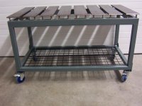
I have wanted a welding table for at least two years now so it's finally time to start on it. I decided on a slat style top using 1 x 4 x 36 cold roll slats mounted on C3 x 5 channel. I would love to do a CAD design first but I can't stand the tedium of trying to learn the available tools. I've tried several and all that happens is I get pissed off after two minutes of trying to translate my layman's understanding of what I want into enginerding terms.

I had originally planned on a 3' x 5' top so I ordered the 1 x 4s cut to 36" and the channel cut to 60". But, when I tried to fit my clamps a 1" gap between two slats, that all went to hell (I'll get to that shortly).

I don't want holes in the top. The plan is to drill a pair of holes about a half inch deep under each end of the slats. I'll use all-thread in the holes with nuts for locking and height adjustment. I decided on about 6" of overhang so the holes will be 24" OC.

Here I'm just laying things out to see where I am. Channel on saw horses with one slat for reference.

View media item 79716
Structural channel has an angle in the web. I bought tapered washers to compensate for that so that the nuts on the underside will set flat. These washers are cast so they're pretty rough. I have radiused the thin edge to allow them to fit as far under as possible (see next pic).

View media item 79717
Here you can see that the radiused edge of the washer allows it to fit better. It's actually pushed in a c-hair too far but you get the idea.

View media item 79718
Next, I needed to know where to mark a line for drilling the holes. I positioned the washer while holding a straight edge where the washer ends. I marked a vertical line on the end of the channel that could then be transferred to the top.

View media item 79719
I used this deal to transfer the mark from the end to the top.

View media item 79720
Now I have a reference line so I can position the washer and use a transfer punch to mark the hole center.

View media item 79721
Then I set up the slide rule to match up with the punch mark and used it to scribe a line the length of the channel. Hmmm...I need to remember to check this to ensure the channel is straight because I'm using the edge as a reference, which might NOT be straight. I think a reasonable tolerance will be 1/32 +/-. Any more and the holes will have to be drilled bigger than 1/2".

View media item 79722
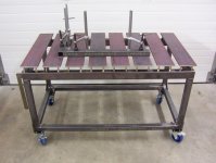
Next, I wanted to see if my planned 1" spacing would work with my collection of C-clamps. Negatory!

View media item 79723
The black clamps are really bad in that the clamp actually tilts backward as it starts to clamp. The result is that I will need 1 5/8" gap. I suppose this could be workable but it means I have to rethink the number of slats. 9 slats comes out to 59 5/8". I might be able to squeeze in one more slat, depending on how I position and space the mounting bolts. I need to meditate on that for a spell.

View media item 79724
View media item 79726
 
Last edited:
To avoid these ads, REGISTER NOW!
OP
J

jimgood

Well-known member
Joined
Aug 4, 2014
Messages
2,394
Location
Marshall, VA
Or, I could order some F-style clamps. I just saw the Stronghand 4-in-1 clamps in 4.5" size for $10 each. They'll easily fit in a 1" gap. The throat depth is 3.25" which should be more than enough for my 4" slat width. Decisions, decisions.
 

bullnerd

Well-known member
Joined
Sep 17, 2012
Messages
5,690
Location
Jersey
Gonna be beefy!

I don't think I've ever seen a clamp deflect that much? Are they quality clamps? HF?
 

1wook

Active member
Joined
Feb 22, 2014
Messages
42
Location
Central MN
The clamps aren't deflecting, they're clamping on the radius and not the "foot". You can see what is happening in his last picture.

Jim, you could keep your spacing and use the clamps you have but only at an angle to the slat instead of perpendicular to it. And then buy some "F" clamps!
 
Last edited:
OP
J

jimgood

Well-known member
Joined
Aug 4, 2014
Messages
2,394
Location
Marshall, VA
Gonna be beefy!

I don't think I've ever seen a clamp deflect that much? Are they quality clamps? HF?

The clamps aren't deflecting, they're clamping on the radius and not the "foot". You can see what is happening in his last picture.

Jim, you could keep your spacing and use the clamps you have but only at an angle to the slat instead of perpendicular to it. And then buy some "F" clamps!
I'm not sure what you mean by the radius but I promise they're not deflecting. They're just barely snug.

EDIT: Ok. I see what you mean now. I thought I was careful not to allow that radius to contact the edge of the slat before the foot. I'll check again. If so, it means an even bigger gap.

I tried using the clamps at an angle with a 1" gap and they don't even pass through the gap. I could use 1 1/4" gap and they would fit through but they would have to be used at a really oblique angle (or is it obtuse). I'll take another measurement of the gap that would be required for the clamps to just reach the middle.

Subscribed. Looks like it will be a nice table.

jimgood real nice and well articulated.:thumbup:
Thank you for sharing..:thumbup:
Thanks, guys. I'll try to make it worth your while. :D
 
Last edited:
OP
J

jimgood

Well-known member
Joined
Aug 4, 2014
Messages
2,394
Location
Marshall, VA
1wook, you were partially correct. I did have one or two of the clamps on the radius. But this one? As evidenced from the crooked handle, I'd say it's been over torqued at least once. I made sure the foot was flat and it wasn't anywhere near the radius and look at that. Yikes!

View media item 79748
This one is better.

View media item 79747
I clamped two at the mid-point of the slat and then turned them until they made contact. This still leaves, at best, a 1 1/2" gap. The other end was at 1 5/8". And these are the skinny clamps. The grey ones in the previous post are a good deal wider.

So, I'm making the executive decision to use a 1" gap and buy F-clamps. Still limits the size of the clamps but I can live with that.

View media item 79746
 

fordkid88

Well-known member
Joined
Nov 10, 2013
Messages
680
Ill be watching this, picked up the steel to do my top this afternoon, and I will order the rest next payday
 

bullnerd

Well-known member
Joined
Sep 17, 2012
Messages
5,690
Location
Jersey
Yeah, deflecting wasn't the right terminology.

Clamp so far out of square, would be better.
 

matt_i

Well-known member
Joined
Mar 14, 2008
Messages
10,722
Location
SE Michigan
I might be about to demonstrate my ignorance here :) but suppose you flipped the cross-channels over 180 degrees, flat side down, flanges sticking up....then you'd have a nice flat spot for the fixed pad on the c-clamp, the plane defined by the tips of the channel flanges would be the "top" for anything large. For a small part that would fall into the channels, you could keep a 12" or 24" square on hand and use that for backup.

An alternative path would be to order something like 2" x 4" x 1/4" box tube, now you have flat top and flat bottom.
 
OP
J

jimgood

Well-known member
Joined
Aug 4, 2014
Messages
2,394
Location
Marshall, VA
fordkid88, that's great. Let us in on the fun!

bullnerd, exactly. I have never bothered to look at these clamps in this way. I know I'll never look at a C-clamp the same way again.

tarmy, your table is one of the ones I'm modeling mine one after.

matt_i, not sure what you're getting at. Flipping the channels 180 degrees just puts the opening on the opposite side, not up. ;) Regardless, if you look at tarmy's pictures above, that's kind of what i'm going for. The slats will be supported by threaded rod in the same way as his slats are supported by bolts welded to the underside. And instead of sq. tube with a flat bar attached, I'm using channel. Having the channel on it's side with the opening facing out allows easy access to the nuts that will be used to tighten the threaded rod after the height is adjusted.

I forgot one other point about my reasoning behind this design (which is still vague and in my head). I want to be able to dismantle the table if I need to. Or to reuse parts off it if I later decide to make it bigger or smaller.
 

tarmy

Well-known member
Joined
May 28, 2014
Messages
4,652
Location
Nor Cal
OP ...if your looking at mine for ideas...note the second photo...that "drip" sheet, unpainted, that slides in the I beams...it catches all the grindings, slag and splatter that drops down...that thing get drug out once a year or so and cleaned off...it also keeps all the **** off the lower end of the table...:bounce:
 
To avoid these ads, REGISTER NOW!
OP
J

jimgood

Well-known member
Joined
Aug 4, 2014
Messages
2,394
Location
Marshall, VA
OP ...if your looking at mine for ideas...note the second photo...that "drip" sheet, unpainted, that slides in the I beams...it catches all the grindings, slag and splatter that drops down...that thing get drug out once a year or so and cleaned off...it also keeps all the **** off the lower end of the table...:bounce:
That's a nice touch! I also looked closer and realized you used I-beam instead of what I described above. I also like the receiver tube. I haven't decided on whether I'm going to include storage under the table or not.
 
OP
J

jimgood

Well-known member
Joined
Aug 4, 2014
Messages
2,394
Location
Marshall, VA
Nothing earth shattering here but I wanted to share this technique because someone might find it useful. I just wanted to ensure that these channels are straight enough. As I said previously, I used the edge to scribe a line where I want to drill my holes for mounting the slats. The mounting studs on each slat will be 24" on center so the point where they go through the channels also needs match that. Hopefully that makes sense.

Anyway, this is how I determined how straight the channel sections are. I used a piece of fishing line and clamped vice grips on each end to weight it. I ran the line over a piece of round rod at each end of the channel. A drill bit would work just as well. Really anything to lift the string slightly off the surface will work; the closer the better. Then I positioned the string directly over the scribe mark and sighted over it to check where the two lines didn't match up. It ended up being less 1/32" off in the center and I think I can live with that.

attachment.php
 

Attachments

  • IMG_2946.JPG
    IMG_2946.JPG
    82.5 KB · Views: 1,105

BD1

Well-known member
Joined
Mar 18, 2007
Messages
4,602
Location
north side
Maybe consider buying two more of the channels. Face channels back to back with gap in between . Drop bolt or all thread rod through top plate and between channels. Secure with square washer and nut .
 
OP
J

jimgood

Well-known member
Joined
Aug 4, 2014
Messages
2,394
Location
Marshall, VA
Maybe consider buying two more of the channels. Face channels back to back with gap in between . Drop bolt or all thread rod through top plate and between channels. Secure with square washer and nut .

Interesting idea. What are we looking for in terms of advantage?
 

MoonRise

Well-known member
Joined
Nov 5, 2010
Messages
4,028
Location
NJ
Maybe consider buying two more of the channels. Face channels back to back with gap in between . Drop bolt or all thread rod through top plate and between channels. Secure with square washer and nut .

Interesting idea. What are we looking for in terms of advantage?

Advantage: Not having to layout, align, and drill 18 bazillion holes in the C-channel. Or having to deal with the (already purchased) bevel washers.

Secondary advantage: More steel! :bounce:

:beer:
 

BD1

Well-known member
Joined
Mar 18, 2007
Messages
4,602
Location
north side
Interesting idea. What are we looking for in terms of advantage?

As stated above. Another advantage it will allow you to change distances between top plate . Weld spacer between channels . This will be like having a I beam for top support with the luxury of bolting plates down at any centers. You won't need those wedge washers either. You could add accessory tool or clamp holders without welding. Drop additional rods between channels and bolt on holders. You could also use all thread rods above table to add temporary support for work at any height. Two vertical rods, nuts washers , angle or channel with holes for rods to pass through. Many options available without making any holes.
 
OP
J

jimgood

Well-known member
Joined
Aug 4, 2014
Messages
2,394
Location
Marshall, VA
Where might I ask?
I'll tell you but I wouldn't bother. These fuckers haven't even received the two I ordered from their supplier (Stronghand Tools). I'm still waiting for them to send me a shipping confirmation. :mad: I have a feeling this is going to end in a disputed credit card charge.

Also, the picture has nothing to do with the product. If you go to Stronghand's website, the UD45 linked above is the Utility Clamp so it does NOT include the extra V-pad and Extender block pictured.

So, caveat emptor!
 

AMCguy

Well-known member
Joined
Dec 23, 2009
Messages
2,022
Location
Sunshine Coast, BC Canada
Or, I could order some F-style clamps. I just saw the Stronghand 4-in-1 clamps in 4.5" size for $10 each. They'll easily fit in a 1" gap. The throat depth is 3.25" which should be more than enough for my 4" slat width. Decisions, decisions.

Good idea to go with "F" style clamps. I've found "C" clamps take up too much room between the slats. The radius is the culprit. You can't use them at the ends either, unless you stand the slat up further from the frame.

I use Ehoma clamps. They are in my opinion the highest quality clamps made at any price point. The radius is very small so they fit tight against the side of a table.

http://www.ehoma.tw/products.php?func=p_detail&p_id=31&pc_parent=6

I used 6'' wide slats for mine. See the link below. You'll be tired of drilling by the time you get those 4'' ones the full width of your table, but you'll probably have a lot more clamping options when you're done.

Great looking build so far.

Glenn
 

Attachments

  • 100_2232.jpg
    100_2232.jpg
    50.8 KB · Views: 110
  • 100_2071_zpsc10152bb.jpg
    100_2071_zpsc10152bb.jpg
    78.4 KB · Views: 121
OP
J

jimgood

Well-known member
Joined
Aug 4, 2014
Messages
2,394
Location
Marshall, VA
AMCguy, that's a nice, simple table. I'm going to sacrifice under-table storage room for having more clamping options. My plan is to have the channel 6" in-board of the slats so there will be about 6"-8" of space between the slats and the table frame at the front and back edge of the table. Something like this (which is not at all to scale):

View media item 80207
 

FallibleFlyer

Well-known member
Joined
Nov 18, 2011
Messages
159
Location
Arizona
Jim, thanks for starting this thread. You actually gave me the inspiration for my own welding table's top.

Good luck on finishing it up, looking forward to it.
attachment.php
 
OP
J

jimgood

Well-known member
Joined
Aug 4, 2014
Messages
2,394
Location
Marshall, VA
Jim, thanks for starting this thread. You actually gave me the inspiration for my own welding table's top.

Good luck on finishing it up, looking forward to it.
Thanks! Nice table!

Hey Jim, ever get your clamps?
I canceled the order. I emailed them and they were responsive. They said it was going to be a couple of weeks before they could get them. So, no. I have not gotten the clamps yet. I'm actually going to hold off anyway as I don't really need them until I get the table built. Which is silly as I could have let the order stand and get them when I get them. :rolleyes:

I finished drilling and tapping the holes in the slats. That was a lot of drilling as I felt compelled to step up in size from 1/8" to 27/64 (tap drill size). I was able to keep them pretty well centered in spite of the runnout on my drill press. The holes were 3/4" deep and I used a 1/2"-13 bottoming tap to thread them. This was my first time doing blind holes. I didn't use a flat bottom drill and the tap is slightly tapered. But I have slightly over a half inch of thread engagement, which should be good enough.

Edit: forgot to mention that I'm stalled a little bit on the table as I have to get my race car project ready to go for its cage install in two weeks.
 
Last edited:
To avoid these ads, REGISTER NOW!
Top Bottom