I have an old Kellogg American compressor, model 321, I believe. There is one feature of this compressor that I do not understand and don't see in the online photos of other similar compressors. There is a tee connected between the tank and the pressure switch, and a 1/4" copper line is connected to that tee. The copper line passes under the platform supporting the pump and connects to line from the pump to the tank inlet, and it connects ABOVE the check valve. Does anyone know the purpose of this 1/4" copper line connection? The reason that I am so interested in this line is that I think that it is allowing air to leak from the tank back through the pump and out through the air intake/filter (because it is connected above the check valve). The check valve is new, and the tank pressure slowly leaks down and there are no other leaks. This compressor was originally used in a car wash. Thanks.

You are using an out of date browser. It may not display this or other websites correctly.
You should upgrade or use an alternative browser.
You should upgrade or use an alternative browser.
Kellogg American Compressor tech question
- Thread starter Zeke60
- Start date
The Tool Tyrant
ALLIANCE MEMBER
Hi Zeke, Your description is a little confusing, but the line that connects ABOVE the receiver check valve to the pressure switch is the line that drains residual pressure from the pump after the switch reaches cut-out pressure. This action creates loadless starting for the motor.
Is your pressure switch plumbed directly into a receiver bung or does the line you're referring to supply receiver pressure to the switch? Photos would help.
Does your 321 have a centrifugal unloader? If it does, that 1/4" line doesn't make sense at all.
Is your pressure switch plumbed directly into a receiver bung or does the line you're referring to supply receiver pressure to the switch? Photos would help.
Does your 321 have a centrifugal unloader? If it does, that 1/4" line doesn't make sense at all.
Last edited:
Thanks for your reply. There is a fitting in the top of the tank, at the "output" end, to which a tee is connected, the straight-thru tee connection is to the pressure switch and the right angle tee connection is for the 1/4" line that passes to the other end of tank ("input" end), and connects to the side of a fitting which connects the line from the pump head to the check valve which is screwed into the top of the tank. And yes, the compressor has a centrifugal unloader and it is in good condition (cleaned, not leaking, weights not broken, etc.). I am not very knowledgeable about compressors, but after reading other forum posts and online information, this 1/4" line seemed to make no logical sense to me since it seems to essentially bypass the check valve in a roundabout way. And sorry, I don't understand what a compressor receiver is, so my description may still be unclear. I will get some photos posted on the weekend. Thanks
454ragtop
Well-known member
Receiver is the tank.
The Tool Tyrant
ALLIANCE MEMBER
The 'receiver' is the air tank that 'receives' the pressurized air.
Here is all your system requires to function ... 1) A source of 'receiver (tank) pressure' to the pressure switch to initiate cut-in & cut-out cycling. 2) A method of relieving residual pump pressure after each cycle (unloader)
You have both. Perhaps at one time it was set-up to be 'dual-run' unit, which means that it could be operated in either 'constant-run' mode or 'start-stop' mode, which if so would require additional plumbing and valving. Another possibility is that you have multiple parts from various machines joined together.
Here is all your system requires to function ... 1) A source of 'receiver (tank) pressure' to the pressure switch to initiate cut-in & cut-out cycling. 2) A method of relieving residual pump pressure after each cycle (unloader)
You have both. Perhaps at one time it was set-up to be 'dual-run' unit, which means that it could be operated in either 'constant-run' mode or 'start-stop' mode, which if so would require additional plumbing and valving. Another possibility is that you have multiple parts from various machines joined together.
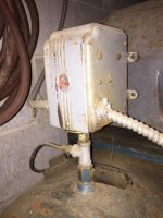
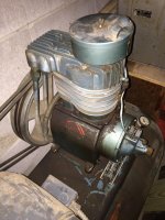
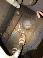
Thanks for your help. Here are some photos. What I am thinking of doing is removing the copper line between the tee below the pressure switch and the inlet tube,and then inserting brass plugs into the two connection points to prevent the leakage back through the compressor. The pressure switch and safety valve both are in working order. Do you see anything in the photos that would create a safety or operation issue with doing that? I use the compressor for occasional use working on farm equipment.
Attachments

The Tool Tyrant
ALLIANCE MEMBER
Before doing so, is the centrifugal unloader unloading at cycle end? I just had a thought that perhaps it wasn't working at some point so the PO changed over to using the pressure switch to unload.
OK, I understand your point, thanks. Am I correct in thinking that the only real way to test that, on this compressor in its current configuration, is to try plugging both of the connection points of the copper tube as I described, then run the compressor a bit to build some pressure, stop it, and then slowly open a connection above the check valve to verify that there is no pressure remaining above the check valve which would load the pump? I am thinking that since I really potentially have two unloading schemes now, I have to eliminate one, to prove that the other is working. I know that the centrifugal loader is clean and weight are ok, but this would be the ultimate test, unless I am missing something simpler?
The Tool Tyrant
ALLIANCE MEMBER
Plug the 2 connections, run it for a half minute or so then shut it down. If the centrifugal unloader is functioning correctly, you will hear it bleeding off pressure as it comes to a stop. If you hear nothing, it's not functioning and you will have residual pressure upstream of the receiver check valve.
Question: where does the discharge line attached to the end of the unloader terminate, as I can't see that point in your pics? If it terminates into the intake, it may be difficult to hear, if so remove the air filter to hear it better.
Question: where does the discharge line attached to the end of the unloader terminate, as I can't see that point in your pics? If it terminates into the intake, it may be difficult to hear, if so remove the air filter to hear it better.
Last edited:
TonyJ
Well-known member
My dad has one and his is set up the same way except his has a steel line run under the pump plate instead of copper
Tony
Tony
MacMcMacmac
Well-known member
Your lines are hooked up wrong. The 1/4" line looks like it is going to the check valve from the tee from the pressure switch, correct? If so, there will be no blow down of the pipe between the check valve and the pump since pressure is constantly being supplied to it through the copper line. Your high pressure exhaust valve is now acting as the check valve, and this pump is not set up to be able to do this. The line on the back of your pump from the round crankcase cover is just there to scavenge oil vapour and blow by so the crankcase doesn't pressurize. The oil vapour is actually useful to lightly lubricate the valves while operating, and another good reason to never use multigrade, detergent engine oil. The line that goes from your cylinder head to the outermost connection on the back of the crankcase is the blowdown line that is supposed to dump high pressure air from the compressor at shutdown. If you are not getting a short blast of air from this valve when the compressor stops, it is not working properly. Get rid of that copper line from the tee to the check valve, and either run a copper line from the port on the check valve to the blowdown valve on the end of the crankcase, or from the blowdown port on the high pressure discharge area on the cylinder head. Right now, it looks like there is no way your compressor is unloading at shut down. The check valve is under constant tank pressure. I am not surprised you are leaking air back through the high pressure exhaust valve, and I am surprised you cant hear it.
The Tool Tyrant
ALLIANCE MEMBER
Mac is spot on! I didn't even notice that the connection at the pressure switch wasn't AT the switch, but rather below it! If your pump DIDN'T have a centrifugal unloader, it would use the unloader port on the pressure switch to unload the residual pressure from the connection above the check valve.
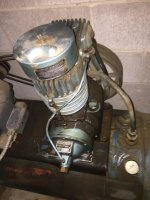
You can see that the galvanized tee was added at some point as it has no paint on it.
You can see that the galvanized tee was added at some point as it has no paint on it.
OK, thanks for your replies. My latest results are that I disconnected the 1/4" copper line at both ends and plugged both connection points with brass plugs. I ran the compressor until it reached 40 psi tank pressure and let it sit for 1 hour. There was no sound of air leakage as before and no pressure loss as before. I started the compressor again for about 1 minute and stopped it. I then immediately loosen the copper line connection at the top of the unloader, and there was no air pressure, leading me to believe that it had unloaded. When stopping the compressor, I cannot say that I can hear an air release, but the motor takes some time to stop and the motor noise may be masking the sound of the air release. Also, I am attaching another picture to show the complete situation. Thanks for everyone'e help.
Attachments

The Tool Tyrant
ALLIANCE MEMBER
Zeke, sounds like good progress! If you disconnect the 1/4" copper line coming out of the end of the centrifugal unloader, you should hear it unload. Being as the line now terminates into the intake via the head is most likely why it is hard to hear.