To avoid these ads, REGISTER NOW!

Between 265 & 485 SQ/FT Kwik Fab's Small Shop

Workspaces sized between 265 and 485 squarefeet.
OP
K

KwikFab

Well-known member
Joined
Jul 27, 2024
Messages
1,330
Location
Central Valley, CA
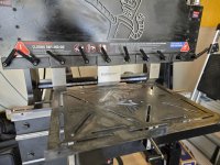
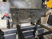
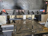
I hope he likes it...

20260814_095505.jpg

20260814_095949.jpg

20260814_101911.jpg

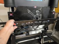
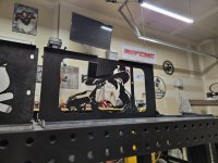
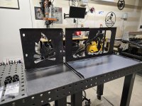
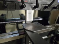
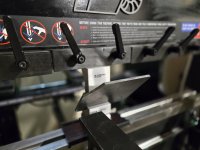
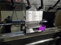
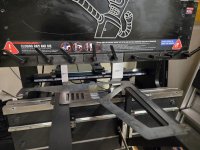
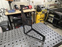
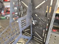
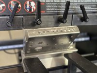
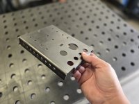
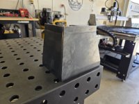
I'm about to get the flanges bent in a second, but looking at it as is, I think this would look much better as a "layered" sign.

Once I reveal to my friend what I made, I'll suggest to him to glue up a colored background, or mount some 16 gauge steel painted a different color.

It'll add both depth, as well as rigidity.
 
To avoid these ads, REGISTER NOW!
OP
K

KwikFab

Well-known member
Joined
Jul 27, 2024
Messages
1,330
Location
Central Valley, CA
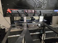
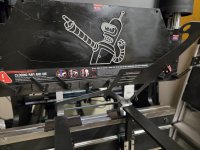
Bender on the bender is priceless! Really cool assortment of projects!

New to fusion how well does the canvas feature work?

How can I put this -

Canvas is probably the slowest process for what I did. This is because many other CAD applications can create an SVG which can be imported into Fusion for immediate use.

Attaching a canvas is just that, a canvas. You still have to draw the item itself and Fusion isn't the best at artistic stuff.

It does come in handy when someone needs a part and they get a template scanned on a flatbed scanner. From there I take that picture and attach it as a canvas, followed by scaling it to a known dimension on the item itself.

This allows me to create as accurate of a copy as possible. Camera phones have a sort of fish eye effect which is why I tell people to not take a picture of the actual part for accuracy reasons.

But, I suffer from memory loss and I can't push myself to learn another CAD program with as often as I use my current one.
 

Blackbyrd

Well-known member
Joined
Nov 28, 2020
Messages
1,196
Location
TN
I was working on a bezel insert (lots of arcs) and it was recommended to use canvas to draw the shape based on the image. But im like 90% close to final shape so it may not be worth it at this point.
 
OP
K

KwikFab

Well-known member
Joined
Jul 27, 2024
Messages
1,330
Location
Central Valley, CA
I was working on a bezel insert (lots of arcs) and it was recommended to use canvas to draw the shape based on the image. But im like 90% close to final shape so it may not be worth it at this point.

For anything that isn't a standard radius or something, I'll definitely use the canvas feature.

Unless the item requested doesn't have to conform to any particular space, etc.

Then I'll just do something clean myself while keeping close to the actual part size.
 

Blackbyrd

Well-known member
Joined
Nov 28, 2020
Messages
1,196
Location
TN
I may give it a try, its a guage cluster bezel that drops into an existing structure but its got multiple arcs that contact exterior wall of what it sets in.

Thanks.
 
OP
K

KwikFab

Well-known member
Joined
Jul 27, 2024
Messages
1,330
Location
Central Valley, CA
I may give it a try, its a guage cluster bezel that drops into an existing structure but its got multiple arcs that contact exterior wall of what it sets in.

Thanks.

Assuming it's symmetrical, you just have to draw half of it followed by mirroring it to make it complete.
 
OP
K

KwikFab

Well-known member
Joined
Jul 27, 2024
Messages
1,330
Location
Central Valley, CA
Them - I have an item, if you can cut it out and bend it.

Me - Sure, send the DXF!

(moments later after trying to decipher things)

Me - Can I see how this whole thing goes together? Maybe some tolerances, etc?

Them -

IMG_6941.jpg

Picture definitely helped, as I wasn't sure whether an item was bent one way or another.

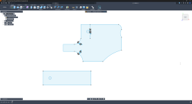
Although, here's the DXF (screenshot) of the provided "design". It's the cardboard piece in the picture above by the way.
Screenshot 2026-08-15 195714.png

What I didn't add is that this is my business partner so I'm allowed to give him **** :ROFLMAO:

I mean, look what I sent him when he finally made the "cardboard" mock up

Screenshot_20260815_200327_Messages.jpg

Some basic modeling told me his DXF was way off and I'd have to redo most of it.

Here's my sketch.

Screenshot 2026-08-15 195645.png

The 3D model.

Screenshot 2026-08-15 195728.png

And the zig zag part I was keeping within a specific tolerance he later provided.
20260815_185405.jpg

What I'm saying is, I'm glad this is the sort of stuff that comes to me almost daily as it really keeps my skills sharpened while not getting complacent and still taking the time to do a test cut and bend.

What's funny though is he absolutely hates anything CAD-related, and while I've always got his back, I've been really trying to encourage him to do the whole thing since he also runs a CNC table.

And for anyone wondering, I will be hitting the tiny flange twice in order to achieve something closer to 85 degrees or so. This is so that the very end acts like a good catch for the latch that goes over it.

Ideally I would run the flange on something like this to achieve a sharper bend.

35Deg2InchDie2Inch_1.jpg

But I'm not going to invest in such tooling for 5 or so parts total unless he wants to order it for me.
 
OP
K

KwikFab

Well-known member
Joined
Jul 27, 2024
Messages
1,330
Location
Central Valley, CA
Cut tons of parts out today, but I'll share last night's bracket.

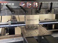
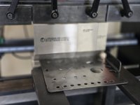
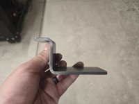
The first bend that needs to be done is the very tip of the catch here. You can see that after it's bent, it more or less tells me how much clearance I need from the die before the second bend.
20260816_130134.jpg

Anyway I had all that calculated so onto the next bends.

20260816_130155.jpg

20260816_130204.jpg

Leaving the larger flange for last. This is because if I had done it first, it would interfere with the punch holder doing the bend at the tip of the catch.

20260816_131045.jpg

20260816_131100.jpg

******* mint.

20260816_131118.jpg

20260816_131126.jpg
 
OP
K

KwikFab

Well-known member
Joined
Jul 27, 2024
Messages
1,330
Location
Central Valley, CA
Here's another item I originally designed, then redid much of, because he immediately grew tired of welding on some little tabs.

This is the center divider of the dual fuel carrier.

20260816_112131.jpg

The original had "slots" where the tabs are, so my business partner can weld on some small mounting tabs. They get welded on as they allow the panel to be bolted in and removed.

This was per his request and I made all the holes and tabs line up perfectly for all the panels that bolt together.

That wasn't exactly easy to get first try lol

Anyway, he recently asked if I can implement some tabs which meant redoing the holes and spacing for everything including - the back panel, the bottom panel, the center divider, and the small front panel.

Had to snap all these pics because he swears everything I do is easy just because I get it all done quickly :ROFLMAO: 😭

20260816_134336.jpg

20260816_134343.jpg

20260816_134440.jpg

20260816_134449.jpg

20260816_134828.jpg

20260816_134838.jpg

20260816_135100.jpg

20260816_135107.jpg

Finally. All that for just a center divider.

20260816_135143.jpg
 
OP
K

KwikFab

Well-known member
Joined
Jul 27, 2024
Messages
1,330
Location
Central Valley, CA
Went better than expected; he has no siblings and his only real friends (or better yet, his future wife) only sees him a few times a year so we were worried he was going to be a lot more selfish than he was today.

His future wife (my daughter in law to be) 2 years ago -

20240629_183937.jpg

The two of them just last month -

20260801_160057.jpg
 
To avoid these ads, REGISTER NOW!
OP
K

KwikFab

Well-known member
Joined
Jul 27, 2024
Messages
1,330
Location
Central Valley, CA
I know it's not but it looks like a cigarette in his right hand.:p

1787413308995.png

You're right it does :ROFLMAO:

It's this little 3D printed airplane he's had forever. I printed it when I made most of his airport for his hot wheels.

20260618_203219.jpg

Y'all are always welcome to donate if you want to help him reach 1,000 cars :lol:

He's about 350 cars short of it...
 
OP
K

KwikFab

Well-known member
Joined
Jul 27, 2024
Messages
1,330
Location
Central Valley, CA
Posting a **** ton of pics in the thread cause why not.

20260822_101719.jpg

20260822_110348.jpg

The other day I posted on here that I revised the fuel jug carrier quite a bit. I say that because the person I make these for wanted a change in the design where he no longer wanted to weld on tabs to the center divider. I explained this quite a bit already in the thread already so today I cut and bent the rear and bottom panels for test fitting purposes and ensuring my math was good (or not).

Here's the rear panel, which only has 3 flanges per side for a total of 2 bends.

20260822_112319.jpg

20260822_112326.jpg

20260822_112440.jpg

20260822_112449.jpg

The bottom panel has flanges on 3 sides with 3 at the bottom, and 2 per side for a total of 3 bends.

20260822_112952.jpg

20260822_112959.jpg

20260822_113403.jpg

20260822_113409.jpg

20260822_113531.jpg

20260822_113538.jpg

And here she is all put together; I really have to give myself a pat on the back for this one because all my math came out right on point. The adjustments I did to the holes on both the bottom panel and rear panel lined up exactly with the center divider. And the center divider flanges were done at the right length, with hole placement where I needed which was twice as hard to figure out since I had to match both left and right sides.

20260822_120355.jpg

20260822_120411.jpg

20260822_120408.jpg
 
OP
K

KwikFab

Well-known member
Joined
Jul 27, 2024
Messages
1,330
Location
Central Valley, CA
Don't trust a customer to know what they're doing.

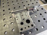
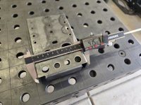
Was sent this yesterday, which I cut and bent right away.

20260825_095749.jpg

20260825_095819.jpg

After sending pictures, we had a short discussion about what it's supposed to be; answer? 5" wide.

I charge only a little more if I'm doing design work, as long as one understands my schedule.

Anyway, I fixed it last night and cut and bent it just now.

20260825_094247.jpg

20260825_094255.jpg

20260825_094639.jpg

20260825_094645.jpg

20260825_094959.jpg

20260825_095005.jpg

For fixing it and not charging you, you'll be happy that it's within 2 thousandths of an inch, and thank me for it too :lol:

20260825_095027.jpg

20260825_095403.jpg

20260825_095411.jpg
 
OP
K

KwikFab

Well-known member
Joined
Jul 27, 2024
Messages
1,330
Location
Central Valley, CA
From time to time, I'll do something completely free.

I may add a stipulation here and there, but one that I find extremely reasonable considering my offer.

A guy in a FB group mentioned something about a bumper he made and asked for some constructive criticism. I simply suggested something like cutting his truck bedside or something to provide functionality as he had made his own "high clearance rear bumper".

To me, this is high clearance as shown on my own truck. For those unaware of the factory setup, my bedside is cut off here so that the bumper mounts high up giving me a huge departure angle.

20260824_190002.jpg

Anyway, since he opted to keep it intact, he was left with a void between the bed side and the area below his tail light.

A company that basically has an F rating with the BBB, has their site down as they're trying to catch up on orders and not go under, so they are unavailable to sell/offer a cap that fills that void.

I told the guy to simply make a cap, since he's a welder but if he needed help I'd be happy to help as needed.

Long story short just make me cardboard cutouts for what you need, scan them, and I'll make the parts for ya for free.

Turned to receiving crudely taken pictures of a tape measure against his truck, to geometries that don't even work :lol:

I decided to mock up for myself what he told me is "exactly what I needed".

20260825_132029.jpg

20260825_135153.jpg

I'm just like..

giphy1.gif

Quick mock in CAD.

Screenshot 2026-08-25 141817.png

And the physical part cut and bent just now.

20260826_101536.jpg

Asked him to just confirm the right edge (passenger side) angle and I'll edit as needed and it's all done!
 
To avoid these ads, REGISTER NOW!
Top Bottom