To avoid these ads, REGISTER NOW!

Layout for dummies - how do I measure this radius?

WhoWhatNow

Well-known member
Joined
Feb 22, 2011
Messages
1,893
Location
Collegeville, PA
How do I measure the radius of this arc?
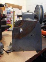
ImageUploadedByTapatalk1404255691.401972.jpg

I need to cut the same radius using a manual milling machine. I do not have a rotary table, so I will be using the method in post #10 of this thread:

http://www.practicalmachinist.com/vb/general/cutting-arc-manual-mill-202096/

I am making a mount for a disc sanding table for my grinder. This is mostly an exercise to see if I can do it.

The table:
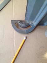
ImageUploadedByTapatalk1404255711.562189.jpg

ImageUploadedByTapatalk1404255722.611965.jpg
 
To avoid these ads, REGISTER NOW!

mechan

Well-known member
Joined
Apr 16, 2009
Messages
401
http://www.mathopenref.com/arcradius.html

Explains it pretty well. The formula you need is about half way down the page.

Best I could do for a sketch on my iPad. :)

y8ydugyq.jpg
 
Last edited:

Guster

Well-known member
Joined
Mar 11, 2012
Messages
1,543
Location
Auckland, New Zealand
Mathematically: method just described.

Manually: you can use the existing arc to create a cardboard template in the same way that you extend a straight line by using part of the curve to extend the curve until you have a complete circle or part thereof to find the two widest points on the circumference in order to derive the diameter.

Sure there is a hundred more but the above are common and accurate enough for what you are doing.
 
OP
W

WhoWhatNow

Well-known member
Joined
Feb 22, 2011
Messages
1,893
Location
Collegeville, PA
Mechan - thanks for the link. That is a good explanation.

Guster - as the pictures show I am clearly not above making a cardboard template. No CNC here!

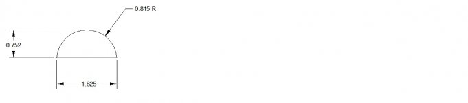
I used the suggested formula and got a radius of 0.815 which is very close to 13/16 (0.8125) A small error in my measurement possibly?
 

Guster

Well-known member
Joined
Mar 11, 2012
Messages
1,543
Location
Auckland, New Zealand
Nothing wrong with CAD - cardboard aided design :)

In fact CAD(the computer variety) is another handy way to derive such measurements effectively.
 

jim1987

Banned
Joined
Feb 16, 2014
Messages
3,582
Location
Ohio
Or could have cardboard template. Then put a piece if string.or what have you beginning to end of desired measurement points, then lay the string on a flat edge ruler.
 

Kevin54

MEMBER EMERITUS
Joined
Jan 12, 2005
Messages
29,341
Location
Urbana, Ohio
Before you start cutting anything, the radius shown, and the pin or stud shown, the pin is not on center of the radius, just in case you didn't know.

Another thing you want to be very cautious of is cutting it like in post #10 like shown in the link you posted. If you are very proficient on a mill, and not just a home hobbyist. or a weekend hack, you'll be fine. But if you bought a mill just to tinker and learn on, you had better be VERY AWARE of climb cutting and conventional cutting. The reason I say that is.....we used to have to do the same thing years ago in our shop, one wrong move and the part can and will get away from you and you can wreck you machine very easy. I've always respected a machine and what it can do. I've watched other use a fixture like that and slice a finger wide open.


Mechan - thanks for the link. That is a good explanation.

Guster - as the pictures show I am clearly not above making a cardboard template. No CNC here!

I used the suggested formula and got a radius of 0.815 which is very close to 13/16 (0.8125) A small error in my measurement possibly?

Also you didn't get a radius of .815, you got a dimension of .815. A very huge difference. You need to also post up the length of "W", then you have to use you Trig formula.

"W" shown is your CHORD LENGTH. That is what you need along with the "H" or HEIGHT. Then use this formula to find out the radius

r = c2/(8h) + h/2 or is simple terms take your Chord length times 2 then divided by 6.52 + .4075
 
To avoid these ads, REGISTER NOW!

Kevin54

MEMBER EMERITUS
Joined
Jan 12, 2005
Messages
29,341
Location
Urbana, Ohio
y8ydugyq.jpg


And like I said earlier, the radius of your table and the bolt is not concentric with each other. Of you look at dimension "W", and the line, the bolt is closer to the left hand side than it is to the right hand side. This allows the table to pivot without getting into the wheel.

Honestly, if it were me, and I was not proficient in trig, geometry, and making radii on a mill without a rotary table, what you should do is take a piece of wood, or MDF to begin with and work with that. First off, the true radius you need is the pivot radius that the stud stick through. If you have a readout on your mill, you can do it in aluminum or you can do it is steel. But you need a trig program to get all of your X/Y Coordinates. Then all you have to do is move your table a few thou each way and plunge cut your endmill straight down.

There is a program out there for a 30 day trial that you can use, and I can walk you right through it very easily. If you are interested, send me a PM and I'll help you out.
 
OP
W

WhoWhatNow

Well-known member
Joined
Feb 22, 2011
Messages
1,893
Location
Collegeville, PA
Kevin - thanks for the feedback.

I am definitely a weekend hack. My plan was to set the work up on the table and raise it to cutting height, take a cut then lower the table to allow me to safely pivot the work back for the next cut. I realize that I will lose any accuracy in the depth of cut, but I don’t think the depth will be as important in this application. And of course shut the machine off after each cut.

I did realize that the stud is not on center to the radius but what I do not know is how to locate it on my new part? Any suggestions?

I will post the measured dimensions up later tonight. If you would check my math I would appreciate it!

Very good idea about using MDF. I think I have some scrap laying around. No DRO unfortunately. It is a bare bones machine with a lot of slop. That just makes it more fun right? :lol_hitti

Thanks again for your suggestions, and may further help will be appreciated!
 

Jackfre

Well-known member
Joined
Dec 26, 2010
Messages
4,426
Location
N CA
How about this? Two good framing squares. Points at the some place on the arc. Draw a line between those points. Turn the blades until numbers match at the intersection of the blades. Go from that point to the middle of the Point to point line and your radius will be established measuring thru that center to the point on the arc.

Oh, and thanks for the Math link. Bookmarked!

Kevin, I wish I knew what you know! Evne a part of it would be nice!:bowdown:
 

Kevin54

MEMBER EMERITUS
Joined
Jan 12, 2005
Messages
29,341
Location
Urbana, Ohio
At the given dimensions, the radius shows about .815 For some reason when i laid it out it came out at .752 instead of .750, but .002 won't make a difference.

Are you absolutely sure the 1.625 is correct? That's not very big compared to the picture. The pic sure looks like it would be bigger.
 

Attachments

  • radius.jpg
    radius.jpg
    14.7 KB · Views: 17
Last edited:

mechan

Well-known member
Joined
Apr 16, 2009
Messages
401
Mechan - thanks for the link. That is a good explanation.

Guster - as the pictures show I am clearly not above making a cardboard template. No CNC here!

I used the suggested formula and got a radius of 0.815 which is very close to 13/16 (0.8125) A small error in my measurement possibly?

I agree with Kevin sure looks like a larger width in the picture judging by some of the surrounding stuff... The .815 would be right of those are the measurements. Fractional sizes are moot in a lot of designs, so regardless what fraction it is close to unless you were figuring out like a fastener or thru hole of some type I wouldn't worry about that for most machining stuff. Machining == decimals :)
 
To avoid these ads, REGISTER NOW!
Top Bottom