To avoid these ads, REGISTER NOW!

Light switches don't use the ground?

GirlnAgarage

Well-known member
Joined
Jan 21, 2011
Messages
4,669
Location
Texas
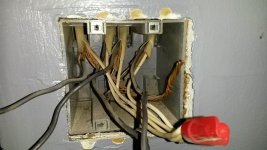
I pulled the cover plate off the garage light switches. I plan to replace them with new ones to match the installed outlets. One switch is for the outside driveway the other for the inside overheads. When I looked in there I see that the ground is not connected to the switches, is that an intentional or normal practice? :headscrat
 
To avoid these ads, REGISTER NOW!

alfredeneuman

Well-known member
Joined
Mar 3, 2011
Messages
4,590
Location
Fullerton, CA
If you're going to replace it with a new one it will come with a terminal to connect the ground to, due to some changes in the Electrical Code.
 
OP
G

GirlnAgarage

Well-known member
Joined
Jan 21, 2011
Messages
4,669
Location
Texas
Yeah the new ones have the ground screw, as do the old ones. I'm saying the ground conductor from the Romex in the wall is not connected to the ground screw on the switch. I guess I'm curious as to why it was done. I'm also hoping that the ground wire is long enough to reach the terminal and it wasn't sniped at the back (I say that because the outlet in the ceiling had this done).
 

exranger06

Well-known member
Joined
Aug 9, 2015
Messages
1,686
Location
CT
Back in the day, light switches were never grounded. They didn't even have a screw to attach a ground wire to. Now, all switches must be grounded per code and of course all switches now have ground screws. I'm guessing the reason your switch doesn't have the ground connected (even though it has the screw) is because whoever installed it didn't know any better. Either he wasn't aware of the code change and he didn't notice the ground screw, or it was a DIYer who only knew how to connect the wires to the new switch exactly how they were connected to the old switch, while not understanding what any of the wires actually did. Regardless, you need to connect the ground wire to the switch; don't leave it disconnected.
 
OP
G

GirlnAgarage

Well-known member
Joined
Jan 21, 2011
Messages
4,669
Location
Texas
Gotcha. I plan to install the ground.

Next concern (hopefully a none issue, I haven't pulled the wires from the box yet, judt thinking over a cup of coffee)
What do I do in the event the ground conductor isn't long enough to reach the terminal? First idea is create a pigtail but I don't think that's right, or even possible if the supply line conductor is too short to reach a pigtail to twist..
 

exranger06

Well-known member
Joined
Aug 9, 2015
Messages
1,686
Location
CT
Creating a pigtail is the proper solution if the wire is too short. If it's too short to twist, try using a Wago connector.
 

fasteddie

Well-known member
Joined
May 25, 2018
Messages
697
Location
NJ
I remember soldering a piece of bare copper to a ground that was cut 1" past the jacket in a switch box. In a plastic box you might be able to pull some more cable through if it doesn't have some kind of clamp on it. Depending on how it's wired, if power hits the switch box first, you will need to connect the ground up to the fixture also.
 
Last edited:

alfredeneuman

Well-known member
Joined
Mar 3, 2011
Messages
4,590
Location
Fullerton, CA
Any ground wire has to be mechanically secured (ie: twisted together) before soldering.
By Code, ground wires can't depend on solder alone to make the connection.
 

stonesfan68

Well-known member
Joined
Apr 19, 2012
Messages
2,762
Location
Houston, TX
Creating a pigtail is the proper solution if the wire is too short. If it's too short to twist, try using a Wago connector.

The Wago connectors work great for this application. I have a lot of switches in my house where they didn’t connect the ground and cut the ground wire short. The Wago sure beats pulling new wires.
 

6PTsocket

Well-known member
Joined
Mar 12, 2014
Messages
4,593
To make the circuit work the ground is not needed, nor is neutral. There is hot and neutral at the load ( bulb or other device). The hot is cut and a piece of 2 wire Romex, BX or whatever makes a round trip through the wall switch and back to the load. Bringing neutral or ground to the switch box has been recently required for safety concerns and control of LED lighting.It is good practice to ground whatever you can. If the box is not metal, ground the switch.
Yeah the new ones have the ground screw, as do the old ones. I'm saying the ground conductor from the Romex in the wall is not connected to the ground screw on the switch. I guess I'm curious as to why it was done. I'm also hoping that the ground wire is long enough to reach the terminal and it wasn't sniped at the back (I say that because the outlet in the ceiling had this done).

Sent from my SM-G900V using Tapatalk
 

acer66

Well-known member
Joined
Dec 4, 2010
Messages
4,418
Location
Western North Carolina
To make the circuit work the ground is not needed, nor is neutral. There is hot and neutral at the load ( bulb or other device). The hot is cut and a piece of 2 wire Romex, BX or whatever makes a round trip through the wall switch and back to the load. Bringing neutral or ground to the switch box has been recently required for safety concerns and control of LED lighting.It is good practice to ground whatever you can. If the box is not metal, ground the switch.

Sent from my SM-G900V using Tapatalk

Not sure when they changed it but I am under NEC 2014 and that requires you to have a ground and a neutral.
 
OP
G

GirlnAgarage

Well-known member
Joined
Jan 21, 2011
Messages
4,669
Location
Texas
Looks like there is plenty of wire, so that concern is put to rest. Although great idea on the Wago, exranger. I will keep that in mind if I run across that situation again. Ditto on the pigtail being correct.

I wasn't expecting for my mind to be confused when I pulled this out, but it is after seeing this many wires. I need to map these so my brain is fully understanding before I pull the switches off.

I know it's hard to see:

- 5 ground conductors twisted in that wrap

- I don't understand the short black wire that goes from one switch to the other. What is that?


I gotta sit down and draw this out. I definitely need direction on how to connect my wires here to get them right.
 

Attachments

  • switch2.jpg
    switch2.jpg
    72.3 KB · Views: 129
  • switch1.jpg
    switch1.jpg
    66.8 KB · Views: 100

exranger06

Well-known member
Joined
Aug 9, 2015
Messages
1,686
Location
CT
You said you have 5 ground conductors twisted together. I only see 4 cables coming into the box. Is there a 5th cable coming in through the bottom of the box that you can't see in the picture?

It looks like the switch on the right has 3 wires connected to the same screw on the bottom. One of those wires is probably the feed that powers both of these light fixtures. The feed connects to the bottom screw, and the switched leg goes to the fixture via the wire connected to the top screw. The short piece of wire that goes to the other switch feeds that switch, and the switched leg goes to the other fixture via the cable connected to the top screw of that switch. The 3rd wire that connects to the bottom screw of the right switch probably goes on to feed something else, maybe another switch box or a string of outlets. The other wire that connects to the bottom of the left switch probably also goes on to feed something else as well.

You can see if I'm right by disconnecting all the black wires from the bottoms of the switches, turning the breaker on, and use a meter to see which wires are hot. If I'm right, there should be only one wire that's hot (that's the feed). In my opinion, a better way to connect those would be to wire nut all those black wires together and have pigtails going to each switch. Then you'd have only one wire connected to each switch terminal, much cleaner.
 
Last edited:

theoldwizard1

Well-known member
Joined
Feb 22, 2011
Messages
43,243
Location
SE MI
Back in the day, light switches were never grounded.
I was trying hard to remember when I saw a switch installed in a box that actually had a ground directly connected.

Of course, all the boxes I might be looking in are metal and the ground IS connected to the box, so "ground" runs through the screw. That was acceptable practice for MANY years.
 

theoldwizard1

Well-known member
Joined
Feb 22, 2011
Messages
43,243
Location
SE MI
What sometime freaks DIY "electricians" out is seeing black on one of the switch terminals and white on the other. This is because power is run from the load center and then a wire is run down to the switch. If this is confusing, put a piece of red tape on that white insulator (red indicates a different hot, not necessarily "hot at all times").


I don't mean to confuse newbies, but the new code says that all boxes MUST have a neutral. In the above case, you would need 3 wire NM-B (black, white and red) so that the white would still ne the neutral. Only required on new construction.
 
To avoid these ads, REGISTER NOW!

theoldwizard1

Well-known member
Joined
Feb 22, 2011
Messages
43,243
Location
SE MI
Not sure when they changed it but I am under NEC 2014 and that requires you to have a ground and a neutral.
Only on new construction or when the wall is already open ! You do not have to open the wall up to pull 3 wire.

Same is true inside the light fixture box if power is fed to the switch box first.
 

alfredeneuman

Well-known member
Joined
Mar 3, 2011
Messages
4,590
Location
Fullerton, CA
I don't mean to confuse newbies, but the new code says that all boxes MUST have a neutral. In the above case, you would need 3 wire NM-B (black, white and red) so that the white would still ne the neutral. Only required on new construction.

Only where a neutral would be impossible to add at a later time.
That rules out conduit if it's size is large enough to add a neutral, and cable that could be fished down at a later time.
 

rwa2004

Well-known member
Joined
Oct 8, 2016
Messages
54
Location
Western PA
When I need to add jumpers like you will need to for grounding the two switches and like it has a jumper power the other switch - I like to use stranded wire.

Some green insulated stranded wire will make it much easier to get the wires shoved back in the box with less worry about a bare copper wire ending up next to a hot terminal screw.

Stranded wire in general is just so much easier to maneuver in those boxes with lots of wires.
 

exranger06

Well-known member
Joined
Aug 9, 2015
Messages
1,686
Location
CT
What sometime freaks DIY "electricians" out is seeing black on one of the switch terminals and white on the other. This is because power is run from the load center and then a wire is run down to the switch. If this is confusing, put a piece of red tape on that white insulator (red indicates a different hot, not necessarily "hot at all times").


I don't mean to confuse newbies, but the new code says that all boxes MUST have a neutral. In the above case, you would need 3 wire NM-B (black, white and red) so that the white would still ne the neutral. Only required on new construction.

I think you meant to say power is ran right to the fixture or outlet, not load center. A load center is a breaker panel.

And OP already has neutrals in this box, so all of this discussion about neutrals being required is a moot point.
 

exranger06

Well-known member
Joined
Aug 9, 2015
Messages
1,686
Location
CT
I was trying hard to remember when I saw a switch installed in a box that actually had a ground directly connected.

Of course, all the boxes I might be looking in are metal and the ground IS connected to the box, so "ground" runs through the screw. That was acceptable practice for MANY years.

That still is acceptable practice, as long as the switches and outlets are the self-grounding type. But when you're using plastic boxes like the OP is, you need to connect a ground wire directly to the switch or outlet.
 

cmandp

Well-known member
Joined
Dec 22, 2011
Messages
1,286
Location
New Jersey
Looks like there is plenty of wire, so that concern is put to rest. Although great idea on the Wago, exranger. I will keep that in mind if I run across that situation again. Ditto on the pigtail being correct.

I wasn't expecting for my mind to be confused when I pulled this out, but it is after seeing this many wires. I need to map these so my brain is fully understanding before I pull the switches off.

I know it's hard to see:

- 5 ground conductors twisted in that wrap

- I don't understand the short black wire that goes from one switch to the other. What is that?


I gotta sit down and draw this out. I definitely need direction on how to connect my wires here to get them right.

That short black wire between switches probably just feeds the power coming from the panel to the other switch.

Going out on a limb here but I bet the wire coming from the bottom is power from the panel.
 

CJ7VFR

Well-known member
Joined
Jan 13, 2015
Messages
2,941
Location
Central New Jersey
What sometime freaks DIY "electricians" out is seeing black on one of the switch terminals and white on the other. This is because power is run from the load center and then a wire is run down to the switch. If this is confusing, put a piece of red tape on that white insulator (red indicates a different hot, not necessarily "hot at all times")....

Every electrician I know/knew would either put a piece of black electrical tape onto both ends of the white wire (at the switch and at either the receptacle or light fixture), or color the ends with a black Sharpie, to indicate that the white wire was part of a switched hot, and no longer a neutral wire.

I have never seen anyone color the ends red to do this. But I guess any other color, other than the wire remaining white, would alert someone to the fact that the wire was not a neutral.

Jim
 

alfredeneuman

Well-known member
Joined
Mar 3, 2011
Messages
4,590
Location
Fullerton, CA
or color the ends with a black Sharpie, to indicate that the white wire was part of a switched hot, and no longer a neutral wire.
But the white was required to the hot, not the switched wire.

Nowadays if no neutral at the switchbox is available, then you've got to run a 3 wire cable from the fixture box's feed.
2 wire switchlegs are a thing of the past in new construction.
 
Last edited:

alfredeneuman

Well-known member
Joined
Mar 3, 2011
Messages
4,590
Location
Fullerton, CA
I hope in the movie series Misson Impossible they have a very different definition of impossible.

In the TV series Barney was the man for the job. He was the technician and could do anything
Tom Cruise of the movies would use his psychic powers granted exclusively to him by the "Church of $cientology" :bounce:
 

fasteddie

Well-known member
Joined
May 25, 2018
Messages
697
Location
NJ
In the TV series Barney was the man for the job. He was the technician and could do anything
There was a scene in that show that still bothers me to this day. Barney had to squirt his little tank of knockout gas into the hotel room next door. He unscrews an outlet in his room then uses special fancy spy tools to unscrew the outlet on the other side of the wall in the adjoining room where the bad guy is. But there were no boxes, receptacles were just screwed into the baseboard. Is that to code on TV? I dunno, maybe they were in Douchebagistan or someplace that doesn't require electrical boxes.
 

CJ7VFR

Well-known member
Joined
Jan 13, 2015
Messages
2,941
Location
Central New Jersey
But the white was required to the hot, not the switched wire.....


I meant basically the same thing. That if you see a white wire with black ends coming off a switch, or coming off of a receptacle or light fixture, that it is part of a switch loop/switched hot wire, and no longer a neutral.

Jim
 

exranger06

Well-known member
Joined
Aug 9, 2015
Messages
1,686
Location
CT
But the white was required to the hot, not the switched wire.

Well I learned something from this thread. I always thought it didn't matter if the white was the hot leg or the switched leg, as long as it had the black tape on it.
 

sberry

Banned
Joined
Jun 18, 2005
Messages
35,747
Location
Brethren, Michigan
Well I learned something from this thread. I always thought it didn't matter if the white was the hot leg or the switched leg, as long as it had the black tape on it.
It confuses the electric ,,,, no,,, well ok, the electric really doesn't know what color the wire is but the fixture should be fed by a black and white wire. Its a kind of,,,, we should all do this the same way sort of thing.
I recently rewired a house, I racked my brain to figure out who did it and then it dawned on me that the same mistake was made by a handyman guy I had seen before. Had a habit of switching neutrals. We scratched out head when testing out some switched outlets and other thing and when I took it apart figured it out. Switched N and used the wrong slot on the recept.
 

exranger06

Well-known member
Joined
Aug 9, 2015
Messages
1,686
Location
CT
It confuses the electric ,,,, no,,, well ok, the electric really doesn't know what color the wire is but the fixture should be fed by a black and white wire. Its a kind of,,,, we should all do this the same way sort of thing.
I recently rewired a house, I racked my brain to figure out who did it and then it dawned on me that the same mistake was made by a handyman guy I had seen before. Had a habit of switching neutrals. We scratched out head when testing out some switched outlets and other thing and when I took it apart figured it out. Switched N and used the wrong slot on the recept.

I'm well aware that the white wire is to be used for neutrals. I'm only talking about when you have a 2-conductor Romex cable run to a switch, and the white wire is NOT used as a neutral. You should always wrap some black tape at the end of the wire to indicate it's not actually a neutral. I already knew all of that. (And yes, I'm aware this is not allowed in new installations anymore) What I didn't know is this: Apparently you can only do this on the hot leg, NOT the switched leg. I thought it didn't matter if the black-taped white wire went on the hot leg or switched leg.
 
Last edited:
To avoid these ads, REGISTER NOW!
Top Bottom