
Does anyone own or use one of these? If so, have you used your powerprobe less as a result?

Here is a description and an ebay link is below:
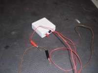
181 Includes LOADpro and #182 Fundamental Electrical Troubleshooting
•LOADpro Test Leads load the circuit to see if current can flow.
•LOADpro identifies these problems fast: High Corrosive Resistance Shorts to Ground Open Circuits
•By loading the circuit, LOADpro makes a voltage drop test “on the fly”.
•Just press the switch – the test results can not lie.
•Use LOADpro w/your DMM and follow our test method - you will find wiring faults quicker.
•LOADpro Test Leads feature SteadyPin Probe Tips, which allows the probe to sit firmly on a male ECM or connector pin.
•LOADpro test leads are OEM approved – finds corroded circuits!
•#182 FET book is 200 pages of basic electricity explained in a way that make it useful in the shop.
•Everything is covered, from batteries, to relays, to schematics – its all in the book!
http://compare.ebay.com/like/200622441644?var=lv<yp=AllFixedPriceItemTypes&var=sbar&_lwgsi=y
Here is a description and an ebay link is below:
181 Includes LOADpro and #182 Fundamental Electrical Troubleshooting
•LOADpro Test Leads load the circuit to see if current can flow.
•LOADpro identifies these problems fast: High Corrosive Resistance Shorts to Ground Open Circuits
•By loading the circuit, LOADpro makes a voltage drop test “on the fly”.
•Just press the switch – the test results can not lie.
•Use LOADpro w/your DMM and follow our test method - you will find wiring faults quicker.
•LOADpro Test Leads feature SteadyPin Probe Tips, which allows the probe to sit firmly on a male ECM or connector pin.
•LOADpro test leads are OEM approved – finds corroded circuits!
•#182 FET book is 200 pages of basic electricity explained in a way that make it useful in the shop.
•Everything is covered, from batteries, to relays, to schematics – its all in the book!
http://compare.ebay.com/like/200622441644?var=lv<yp=AllFixedPriceItemTypes&var=sbar&_lwgsi=y


")


