jdcompman
Well-known member
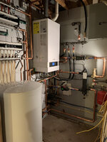
I'm looking for some help in troubleshooting my radiant system that I just put together. The problem I'm having is that I'm only getting about 3.5gpm through the entire system. System is 12 loops of 1/2", all less than 300' and very similar lengths. Everything is on one zone (big open building). With this flow, it nets about .29gpm through each loop, which seems extremely low. Based on my calculations and circulator setup, I feel like this system should have no problem running upwards of 12gpm. I just can't figure out what is causing all of the restriction. Circulators are both UPS 15-58 FC. I have very thoroughly purged the air from each loop individually as well as the rest of the system. All of the copper piping is 3/4" except the runs to the manifolds, which are 1". Hopefully someone smarter than me can help point me in the right direction. The system is currently working and heating the space, I just feel like it's not efficient at all.
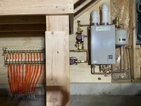
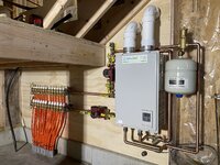
First picture is of the system as it stands today (boiler output is 100 now) and the other pictures were as I was building it, just shows more angles.
Thanks in advance for any help.

First picture is of the system as it stands today (boiler output is 100 now) and the other pictures were as I was building it, just shows more angles.
Thanks in advance for any help.
Attachments
-
 919CD91B-B1FA-4ACB-B499-EFE53610C3E7.jpeg361.2 KB · Views: 86
 -
 4667F8BF-E9A7-4434-B091-C06073CA079A.jpeg398.7 KB · Views: 73
 -
 81AF2820-2070-41C1-9199-5C16600E12EB.jpeg344.2 KB · Views: 69
 -
 DD829E38-62D2-45F3-8C7E-4B91D0D92B7D.jpeg340.1 KB · Views: 72
 -
 EDD1AD75-DEC3-4558-8D57-AB5C2D424BBB.jpeg420 KB · Views: 95