BigMike782
Well-known member
I will be glad to add to this thread........in another 40 or 50 yrs when I am any where near as smart as you guys!
Thanks for this amazing thread
Thanks for this amazing thread

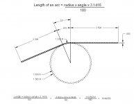
Here are a couple of quick sketches showing how to measure for sheetmetal length needed to fab up a part. These are just simple sketches but will also apply to complicated parts if you know your angles and radii. There are quite a few charts out there showing bend radii dimensions and almost all of the charts vary from each other. Over the years I have found this is the best way to figure it. Most will come to within .010 of what is needed depending on the materials. I always use the middle of the material for the radius. So note the material thickness of the sections shown. I forgot to mention on the second sketch that the inside radius is 1/2" or .500
I'll post up a more complicated sheetmetal part in a little while.
Kevin...are you not familiar with bend radius and set back charts for sheet metal?? If not I will try to find a source on line to reprint. I use these charts to make parts for airplanes all the time. They usually include standard and minimum bend radiuses for a given material and spring back for different materials. With these charts you can look up the bend allowance or setback and calculate your flat pattern before you bend anything. They also include the K factor for when you bend over 90 degrees.
Buy a machinery handbook!!! I have two at my desk at work, one in my garage and one at my desk at home.
No, it was tip... It is a shop necessity


Agreed!
RJ,
How about how to tram the head of a mill? I'd do it, but I don't have a mill in my garage (yet). Another good one is how to use a sine bar.
While we're on the subject of tramming the head of a mill, whenever I move the head of the mill for angled cut or move the mill vise, I always write on the vise or table "Tram Head" or "Align Vise" with a sharpie so I remember to re-align everything when done. The other method is to leave the head or vise so far out out alignment that there is no doubt that things need to be squared up if you (or someone else) need to work on the machine.
Great tip for cutting smooth joining surfaces in tubing. Thanks!
Nelson
I owe you a case of beer for this.

there is a commercially available jig/fixture for use with a drill press and a hole saw for fish mouthing pipe at any angle. i have never used one, but am curious why you go through all that trouble when the jig seems so simple? thanks for humoring my curiosity.

You would think I would of gotten myself a notcher by now.
George, you get a 10 point gold star for that one! I had not seen a rivet fan before, but it will become one of my future shop tool projects. Whether bolts or rivets, that takes a lot of work out of a linear layout.

Nasty, I know that you know, but you could also make up three aluminum blanks with holes and unbolt the steel jaws and bolt on the aluminum jaws. We used to keep about a half a dozen sets of aluminum jaws for specialty jobs.
Take an appropriately sized hex nut, and using a vise, press the nut onto the drive square of the needed tap.
Any pointers for turning parts and getting a smooth finish? I manage to get some smooth finishes and some not

Any pointers for turning parts and getting a smooth finish? I manage to get some smooth finishes and some not
Whenever you set up on the parallels, hammer the part down with a dead blow hammer. If you can move the parallels afterward, you are not set up properly. Indicate the bottom of the vise also. It needs to be true to prevent milling a taper. First rule of machining for you, other than safety, is never assume ANYTHING. On critical operations, measure every drill bit right before you chuck it. If not, you will learn why. Never remove a part immediately after milling. Think first. Make sure everything is as needed before removing that part, or you may blow the next step in the operation. Make a 8 inch long bar with a T shaped linear profile, to clamp in the vise, with various tapped holes in it to hold odd size and shaped parts. You can even mill curved slots in parts with it. Control the situation and you control the job.
Thanks Kevin, I'm not positive about the tip as I assumed it was a setup issue. It's at work were there are a few mechanics that actually use the lathe for all kinds of stuff and I've thought about getting bits and tips to keep in my toolbox.