To avoid these ads, REGISTER NOW!

Made a "manual auto drain" (MAD) for my compressor!

lametec

Well-known member
Joined
May 5, 2008
Messages
2,099
Location
Michigan
Was getting tired of crawling behind the Bridgeport, over jugs of oil, and under the compressor to drain it.

Automatic drains drain too often for my taste. I don't use the compressor enough to warrant that frequent drainig. Came up with this idea.

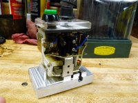
Started with a standard 8-pin time delay relay. Yanked off the bottom of it and milled up a new bottom out of aluminum. This way it can bolt directly to the compressor, and no need for a socket and exposed live wires.

I had to put a series resistor into the circuit since the relay wants 120VAC and I'm running it off the 240VAC already at the compressor. Didn't want to have to run another electrical wire to it. I drilled a hole through the aluminum base and put the resistor inside it. This way the aluminum acts as a heat sink. The resistor is only rated for 3W, and it dissipates about 6W. It's what I had on hand.

The timer was an old electromechanical one I got for free a while back. All I needed to do was add a switch to trigger it. Well, I didn't want the switch to be external, so I drilled the timer body to mount it internally. This meant I had to move some internal workings of the timer around to make room. The black blob in the center of the innards picture is the micro-switch that was moved. Some of the wires were (re)moved to gain the functionality I needed.

A couple inline fuses protect the circuit.

Add to this a Parker 1/4" solenoid valve (from eBay) and some fittings and hose, and you get this.

Now all I have to do is push the green button, and it drains for 20 seconds. It's adjustable from 0-180 seconds.

The end of the drain hose goes through the wall to behind the garage. Quiet, and no mess to capture/clean up.
 

Attachments

  • Compressor manual auto drain 001 (Small).jpg
    Compressor manual auto drain 001 (Small).jpg
    48.2 KB · Views: 243
  • Compressor manual auto drain 002 (Small).jpg
    Compressor manual auto drain 002 (Small).jpg
    50.5 KB · Views: 258
  • Compressor manual auto drain 007 (Small).jpg
    Compressor manual auto drain 007 (Small).jpg
    62.5 KB · Views: 279
To avoid these ads, REGISTER NOW!
OP
L

lametec

Well-known member
Joined
May 5, 2008
Messages
2,099
Location
Michigan
Solenoid valve is 240V.

I figured resistance by measuring the current draw of the timer at 120V. 50ma in this case (timer relay energized). I needed to drop 120V, so Ohm's law:

120V / 0.05A = 2400Ohm.

I didn't have a 2400Ohm resistor, so I used a 3300Ohm instead. I tested the timer and it kept working properly down to about 90V, so the 3.3K resistor does the trick. I didn't measure actual voltage applied to the relay with the 3.3K resistor, but I'm guessing somewhere between 100V and 110V.
 
OP
L

lametec

Well-known member
Joined
May 5, 2008
Messages
2,099
Location
Michigan
Yep, measured from a 120V outlet. In my case off my variac, but that's really not relevant.

This is an AC timer which also has a little motor in it to move the mechanical timer, so I couldn't just measure coil resistance. On a DC controlled solid state timer I probably could have.

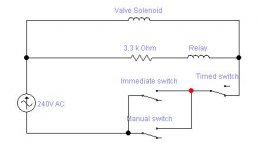
I attached a diagram of the circuit.

Manual switch: The nomally open green push button.
Immediate switch: A normally open switch in the timer relay that closes the moment the relay is powered up.
Timed switch: A normally closed switch in the timer relay that opens after the timer period elapses.
 

Attachments

  • Compressor manual auto drain schematic.jpg
    Compressor manual auto drain schematic.jpg
    11 KB · Views: 32
Last edited:
To avoid these ads, REGISTER NOW!
Joined
Apr 18, 2011
Messages
20
That's a frugal approach to solving your problem.

The auto drain valves I've seen so far cost around $100.00 or more. Plus they add complexity; something else to break or monitor for proper operation, which I try to avoid.

My compressor came with a needle valve you can crank open on the bottom of the tank. What I did was just open it a tiny bit... a little hiss is all it emits. It takes about 24 hours before the 60 gallon tank is discharged by this little leak. My idea is that the water will always be able to escape and not build up. I haven't heard anyone else put forward this idea. Am I missing something? To me it seems like the easiest and simplest way to solve the problem.

Another idea I had was to plumb a hose from the bottom of the tank to a 1/4 turn valve on the wall by the door, and as I left the garage for the day, just give the valve a crank for a couple of seconds. No way its gonna fill up with water in one day with the moderate use I give it. But, the barely opened needle valve seemed simpler. It likely wont fail and doesnt require any maintenance. Do you think that is a good idea?
 

therealwormey

Well-known member
Joined
Oct 18, 2010
Messages
486
That's a frugal approach to solving your problem.

The auto drain valves I've seen so far cost around $100.00 or more. Plus they add complexity; something else to break or monitor for proper operation, which I try to avoid.

My compressor came with a needle valve you can crank open on the bottom of the tank. What I did was just open it a tiny bit... a little hiss is all it emits. It takes about 24 hours before the 60 gallon tank is discharged by this little leak. My idea is that the water will always be able to escape and not build up. I haven't heard anyone else put forward this idea. Am I missing something? To me it seems like the easiest and simplest way to solve the problem.

Another idea I had was to plumb a hose from the bottom of the tank to a 1/4 turn valve on the wall by the door, and as I left the garage for the day, just give the valve a crank for a couple of seconds. No way its gonna fill up with water in one day with the moderate use I give it. But, the barely opened needle valve seemed simpler. It likely wont fail and doesnt require any maintenance. Do you think that is a good idea?

i dont know but that sounds like a constant leak to me.i dont like air leaks..maybe i just dont get where your going with that.why not just remove the petcock drain and replace with one of those with a pull cable like on a big rig if its a hassle to get to the petcock...........
 

garfunkle24

Well-known member
Joined
Mar 18, 2008
Messages
3,429
Location
Saskatoon, Canada
Solenoid valve is 240V.

I figured resistance by measuring the current draw of the timer at 120V. 50ma in this case (timer relay energized). I needed to drop 120V, so Ohm's law:

120V / 0.05A = 2400Ohm.

I didn't have a 2400Ohm resistor, so I used a 3300Ohm instead. I tested the timer and it kept working properly down to about 90V, so the 3.3K resistor does the trick. I didn't measure actual voltage applied to the relay with the 3.3K resistor, but I'm guessing somewhere between 100V and 110V.

I'm not really clear on this. Don't resistors impede current flow, not voltage?

I thought to do this you would need two equal resistors in a "voltage divider" setup. Isn't your formula just the internal impedance of the timer based on it's supply voltage and current draw?

I'm a DC guy, not much AC knowledge, so I might be way outta wack here.
 
Joined
Apr 18, 2011
Messages
20
I'm not really clear on this. Don't resistors impede current flow, not voltage?

I thought to do this you would need two equal resistors in a "voltage divider" setup. Isn't your formula just the internal impedance of the timer based on it's supply voltage and current draw?

I'm a DC guy, not much AC knowledge, so I might be way outta wack here.

A resistor across a voltage source flows current and drops a voltage across the resistor. Ohms law determines the exact numbers.

As I understand it, he measured the current draw of the relay across a 120 source. Then he pretended that was a resistor. What resistor has the same behaviour? Ohms law gave him the answer.

He then put that resistor in series with his relay across the 240. Since the real resistor also drops 120, that leaves the perfect voltage for his relay. He went safer ( less likely to burn ) by using a larger resistor because it was convenient to source that value rather than the calculated one.

Hope that helps... maybe not. His explanation was the simplest and best one... the only reason I'm offering this is you seemed to have a little trouble with his.
 
Joined
Apr 18, 2011
Messages
20
i dont know but that sounds like a constant leak to me.i dont like air leaks..maybe i just dont get where your going with that.why not just remove the petcock drain and replace with one of those with a pull cable like on a big rig if its a hassle to get to the petcock...........

Yes, its a very small air leak. I assume that the actual amount of air that escapes is comparable to periodic blasts through an auto/semi-auto drain valve.

Where I'm going with it is no special valve or moving parts are required, you just crack the thing open a wee bit and forget about it.

I apologize for bringing this up here as it has little to do with the topic the OP wished to share.
 
OP
L

lametec

Well-known member
Joined
May 5, 2008
Messages
2,099
Location
Michigan
I'm not really clear on this. Don't resistors impede current flow, not voltage?
Yes. But as a result, there's also voltage across the resistor. You can't have current without voltage unless you're dealing with superconductors with absolutely no internal resistance.

I thought to do this you would need two equal resistors in a "voltage divider" setup. Isn't your formula just the internal impedance of the timer based on it's supply voltage and current draw?
Yes and yes. In my case one of the "resistors" is the timer itself. I know I have to drop 120V across my series resistor to end up with 120V on the other "resistor" (timer). Since I know the current draw, I can easily calculate an appropriate series resistor.

Hope this clears it up. Not sure how else to explain it.
 
To avoid these ads, REGISTER NOW!
Top Bottom