To avoid these ads, REGISTER NOW!

Mag motor starter

bowtieboy77

Member
Joined
Mar 6, 2019
Messages
15
Location
Watford
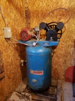
First day member and first question but have noticed some very electrical wise members. I brought home a 80gal upright compressor from work about 5yrs ago and just now getting it hooked up. The compressor pump was beat and non rebuildable so it went to scrap. The 1 phase 5hp motor is fairly new and was told it was replaced shortly before compressor was taken out of service. I am picking up a 5hp compressor pump on the weekend.

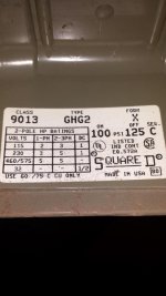
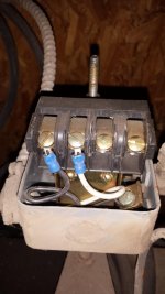
My question is I acquired a furnas 11da3b manual motor starter. I know I can use a 3 phase motor starter to power a 1 phase motor but I am wondering if this starter will work for a 1 phase 5hp motor. On the sticker if I am understanding it will work on 110 1phase 1.5hp, 110v 2-3phase 3hp,
208-220 1phase 3hp, 208-220 2-3 phase 7.5hp. No where on it does it have 5hp motor listed. The motor starter that used to run this compressor is still on the wall at work but may not be in 10hrs lol. My other option is to buy a 220v 1phase 5hp mag motor starter with thermos protection for about $65 on ebay.

Also I am planning on using 10/2 armoured cable from a 40amp breaker in panel approx. 20' away. Is this a heavy enough gauge of wire? The motor max amps is 40 and fla is 23 rpm 1740. Any help is appreciated.
 
Last edited:
To avoid these ads, REGISTER NOW!

Norcal

Well-known member
Joined
Mar 16, 2008
Messages
13,763
A manual starter is not going to work, a magnetic starter is required as the pressure switch has no place to be wired in with a manual starter and the pump will keep running even after the safety valve pops open.
 

mm08822

Well-known member
Joined
Jan 13, 2012
Messages
5,978
Location
NJ
I can’t find details for that starter googling. However, you indicate it as a manual starter. A manual starter means hand operated- on/off. The rating of it is not large enough. Post a pic of it to be certain.

You need a pressure switch (in the correct pressure range) to provide 2-wire control to a magnetic starter. The starter needs to be rated at least 5HP and 240vac.
Size the thermal protection from the motor nameplate FLA value – 23A..

You will need #10 Copper MC cable or #10 Copper THHN in conduit.

Max cb size can be 60A. If you have a 40 or 50a breaker already, try that before having to buy a 60A.


You could also use a 5 hp rated pressure switch and control motor directly if the motor has built in thermal overload protection. Using the motor starter is the better way to go.

Is the comp within sight of the panel?
 
Last edited:
OP
B

bowtieboy77

Member
Joined
Mar 6, 2019
Messages
15
Location
Watford
Well it is starting to make sense now. The starter is a manual starter. The motor is thermally protected, and the pressure switch used is a square 9013 model. This explains why a manual controller was used. The pressure switch label states that for 230v it will operate a 1 phase 3hp or a 2-3 phase 5hp. It does not state it will operate a 230v 1 phase 5hp. Will it work? I brought it home complete the way it was being used at the shop.

Its been many years since I removed the motor so I forget where the motor wires connected to the pressure switch. The terminals are labelled from left to right line,load,load,line. Looking at the empty terminals it looks like the motor wires was connected to 1load and 1line and ground screw. But a video I watched states the incoming power is connected to both outside screws which are both line terminals. Would I be better to use the square pressure sensor that has the on and off switch built in?
 

Attachments

  • 20190306_184359.jpg
    20190306_184359.jpg
    57.5 KB · Views: 24
  • 20190306_184409.jpg
    20190306_184409.jpg
    61.4 KB · Views: 19
OP
B

bowtieboy77

Member
Joined
Mar 6, 2019
Messages
15
Location
Watford
Here is the id tag off the motor. I apologize its upside down. I guess what I am wondering is Should I get another pressure switch that is rated for 1phase 220 5hp motor and use a manual control, or buy a mag motor starter and wire the pressure switch to the power side of mag starter coil?
 

Attachments

  • 20190305_152340.jpg
    20190305_152340.jpg
    116.9 KB · Views: 21

mm08822

Well-known member
Joined
Jan 13, 2012
Messages
5,978
Location
NJ
Well it is starting to make sense now. The starter is a manual starter. The motor is thermally protected, and the pressure switch used is a square 9013 model. This explains why a manual controller was used. The pressure switch label states that for 230v it will operate a 1 phase 3hp or a 2-3 phase 5hp. It does not state it will operate a 230v 1 phase 5hp. Will it work? I brought it home complete the way it was being used at the shop.

Its been many years since I removed the motor so I forget where the motor wires connected to the pressure switch. The terminals are labelled from left to right line,load,load,line. Looking at the empty terminals it looks like the motor wires was connected to 1load and 1line and ground screw. But a video I watched states the incoming power is connected to both outside screws which are both line terminals. Would I be better to use the square pressure sensor that has the on and off switch built in?
....
I would not use it on a 5hp motor. It is only rated for 3hp. It will have a short life if used.

You need a 5hp ps if you are going to use it to directly control the motor.

Cut sheet I found shows power on outside terms and motor on the inside terms.

As I said earlier, a starter is much better - longer life. The ps you have now will be fine to control the starter. I assume it has an unloader valve.
You would need a nema 1 size starter and a set of heaters for 23a.
 

wyliesdiesels

Well-known member
Joined
Aug 14, 2012
Messages
20,031
Location
Modesto, CA
Well it is starting to make sense now. The starter is a manual starter. The motor is thermally protected, and the pressure switch used is a square 9013 model. This explains why a manual controller was used. The pressure switch label states that for 230v it will operate a 1 phase 3hp or a 2-3 phase 5hp. It does not state it will operate a 230v 1 phase 5hp. Will it work? I brought it home complete the way it was being used at the shop.

Its been many years since I removed the motor so I forget where the motor wires connected to the pressure switch. The terminals are labelled from left to right line,load,load,line. Looking at the empty terminals it looks like the motor wires was connected to 1load and 1line and ground screw. But a video I watched states the incoming power is connected to both outside screws which are both line terminals. Would I be better to use the square pressure sensor that has the on and off switch built in?

That label must be old as there is no more 2 phase unless one lives in philly and even then it is a 4-wire system.

I would definitely NOT use that. Buy a mag starter rated for 5hp.

Here is the id tag off the motor. I apologize its upside down. I guess what I am wondering is Should I get another pressure switch that is rated for 1phase 220 5hp motor and use a manual control, or buy a mag motor starter and wire the pressure switch to the power side of mag starter coil?

I would not bother with a 5HP pressure switch.

The proper thing to do is use a mag starter.
 

matt_i

Well-known member
Joined
Mar 14, 2008
Messages
10,728
Location
SE Michigan
A 5hp pressure switch will last quite awhile. MY ingersoll rand T30 compressor has been rocking a 5hp pressure switch (think its a Square D un-labeled) new from the IR factory for the last 21 years and is still going. Its not the absolute best practice but its not quite a pit of quicksand either.
 

cabranch47

Well-known member
Joined
Jun 8, 2011
Messages
103
Location
Louisiana
A little different question but along the same lines. I have a 60 gal. 3 hp Northstar compressor, 230V, 20 Amp.. I would like to wire it so that it is only energized when I turn my shop lights on. What type of motor starter would I use?
Thanks for any help.
 

wyliesdiesels

Well-known member
Joined
Aug 14, 2012
Messages
20,031
Location
Modesto, CA
you would need a mag starter and then there is several options.

You could use a relay tied to the light switch with one of the mag starter coil legs running through the relay.

im in too much of a hurry to draw a diagram for ya
 
To avoid these ads, REGISTER NOW!
OP
B

bowtieboy77

Member
Joined
Mar 6, 2019
Messages
15
Location
Watford
Well thank you for all the help full info. I ordered a 5hp 1 phase magnetic motor starter last night should be here next week. I will be using the existing pressure switch to control the starter coil. Going tomorrow to purchase the new compressor pump. More questions might come up while I am assembling but they will be on a new thread. Thanks again.
 

alfredeneuman

Well-known member
Joined
Mar 3, 2011
Messages
4,581
Location
Fullerton, CA
Be sure to hook up by the diagram, inside of the lid, for 2 wire control instead instead of 3 wire. If 3, then it will bypass the pressure switch and the compressor won't shut off.
 
OP
B

bowtieboy77

Member
Joined
Mar 6, 2019
Messages
15
Location
Watford
I specifically ordered a 1 phase controller so we will see what it looks like but I will make sure I inspect the diagram.
 
OP
B

bowtieboy77

Member
Joined
Mar 6, 2019
Messages
15
Location
Watford
Well thanks for the help and here is update. This has been quite a annoying project. I needed a new fitting for the discharge line into tank. No one stocks 3/4 inverted flare fittings so I ordered through Fastenal. Next I had to make a new 3/4 discharge line but my flaring kit stops at 1/2". I was not going to buy a $100 flaring kit for 2 flares. Luckly I friend used to work for a heating and cooling place so he had one. Very few stores stock soft 3/4 copper in rolls. They can order it in but want me to buy whole roll for over $100. Rigid 3/4 is bigger o.d so it wont fit in flaring tool. I did find a hardware store that had a few feet of it if not I was going to stop in at a local heating and cooling contractor. I am not completely happy with the discharge line in picture but with out a tube bender this is as tight as I could bend with out crimping.

I went to do the initial turn on today and compressor did not turn on. I had 120v at each leg of my supply wires to mag switch. If I manually engaged the coil I would get 120v through coil to each leg of the thermal overload outputs but if I put volt meter leads on both of the supply legs I would get 0 volts. I checked voltage at the double pole breaker I installed and both legs had 120v but both together had 0v. After a google search I realized I put the breaker in the wrong spot so both legs were on the same phase. Move the breaker down one slot and problem solved. Next problem was the motor was spinning wrong direction. Luckily there was a good description on the motor electrical cover stating what wires to switch and the wires were nicely labelled. Only other thing I had to do was adjust pressure switch from 160psi cutout to 135psi.

Thanks again for the help. Next I start running pipe around shop walls.
 

Attachments

  • 20190322_170915.jpg
    20190322_170915.jpg
    143.9 KB · Views: 15

wyliesdiesels

Well-known member
Joined
Aug 14, 2012
Messages
20,031
Location
Modesto, CA
Well thanks for the help and here is update. This has been quite a annoying project. I needed a new fitting for the discharge line into tank. No one stocks 3/4 inverted flare fittings so I ordered through Fastenal. Next I had to make a new 3/4 discharge line but my flaring kit stops at 1/2". I was not going to buy a $100 flaring kit for 2 flares. Luckly I friend used to work for a heating and cooling place so he had one. Very few stores stock soft 3/4 copper in rolls. They can order it in but want me to buy whole roll for over $100. Rigid 3/4 is bigger o.d so it wont fit in flaring tool. I did find a hardware store that had a few feet of it if not I was going to stop in at a local heating and cooling contractor. I am not completely happy with the discharge line in picture but with out a tube bender this is as tight as I could bend with out crimping.

I went to do the initial turn on today and compressor did not turn on. I had 120v at each leg of my supply wires to mag switch. If I manually engaged the coil I would get 120v through coil to each leg of the thermal overload outputs but if I put volt meter leads on both of the supply legs I would get 0 volts. I checked voltage at the double pole breaker I installed and both legs had 120v but both together had 0v. After a google search I realized I put the breaker in the wrong spot so both legs were on the same phase. Move the breaker down one slot and problem solved. Next problem was the motor was spinning wrong direction. Luckily there was a good description on the motor electrical cover stating what wires to switch and the wires were nicely labelled. Only other thing I had to do was adjust pressure switch from 160psi cutout to 135psi.

Thanks again for the help. Next I start running pipe around shop walls.

Wait what?

Any double pole breaker should connect to 2 opposite stabs giving 240v no matter which position its in in the panel since bus stabs alternate between phase legs.

What brand of panel do you have?

Are you sure its a double pole breaker?

Or are you using 2 single pole breakers?
 
Last edited:
OP
B

bowtieboy77

Member
Joined
Mar 6, 2019
Messages
15
Location
Watford
It is a federal pioneer panel and down the center is silver squares. I had the double pole breaker in one of the squares but had to move it down so it was connected to 2 of the squares. I always thought a double pole breaker could be installed anywhere in the panel to give 240v but that is not the case in this panel. Important thing is it is now working.
 
To avoid these ads, REGISTER NOW!
Top Bottom