
You are using an out of date browser. It may not display this or other websites correctly.
You should upgrade or use an alternative browser.
You should upgrade or use an alternative browser.
Magnetic Starter ,Control Wires?
- Thread starter Arnie7
- Start date


RPH
Well-known member
Starter is nothing more than large relay. The one you show is for a 3 phase motor.
1L1, 3L2, 5L3 is the line power in. 2T1, 4t2, 6t3 are power to the motor. A1 & A2 are coil power to energize the relay. On the far right is the off & on control pb's to turn. Coil on / off. Also there is the contacts 13 & 14 that are used as the holding circuit to the coil so you don't have to stand there holding the on pb on. The little bumps between the motor side and the motor are overloads to cut the unit contactor coil power in case of malfunction. Proper sized overloads are required for your motor. Also if your motor is single phase you need to come out of the overload on one leg and feed it back into the line side on the open set of contacts to keep all happy in the circuit.
Hope this helps.
Thanks RPH !
L3 Has A Lead To The overload switch . Do I Connect One Hot to it ( L3 )
,and one hot to L2 ?
Compressor out T1 and T3 ?
What teminals do i connect my 2 control wires ( number? ) 13 and 14 ?
if so is it the lower set of connections or 2 top on left.
the pic is hard to see, the left side has 4 connections 13,21,22,14
Thanks Arnie
buzz4041
Well-known member
You realize you have a 3 phase contactor and are describing a single phase motor. On the diagram all dashed lines are user supply (you). Do you have an on/off switch and a pressure switch for the control circuit ? You will need this to operate the compressor. Your diagram shows a standard start/stop circuit but you only need a maintain on/off switch ahead of the pressure switch wired between 1L1 and A2 as you do not need the seal in contact your pressure switch will do that for you. You will need to jumper from 2T1 OL to 3L2 contactor with FLA rated wire as RPH stated and then connect your motor to 4T2 OL and 6T3 OL. You won't be using the aux contacts on the contactor 13,14,21,22. You will need to set your OL to the nameplate rating of your motor which should be around its lowest setting of 22 amps.Why are you putting a contactor in for a 5HP motor anyhow ? Above 5HP ok but not needed in this case.
Honestly you need a new diagram made up if your not electrical savy or else you will have problems. If nobody else can supply I will make one tomorrow and post for you.
Honestly you need a new diagram made up if your not electrical savy or else you will have problems. If nobody else can supply I will make one tomorrow and post for you.
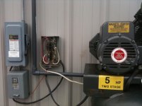
Moved In To This Shop, They Had A 3 Phase Compressor In This Spot,i pulled 10g to the outside cut off , pannel has double35amp
Useing the out side cut off ! eliminating the there old mag cont., the one to this compressor shorted last week from the rain. i am installing a waterproof box and new mag starter ,MS-P30T Shihlin . The Compressor Has A Preasure Switch On It, Not sure if N/O or N/C at this time. I Assume the contactor throws threw all 3 legs ,not sure where the hold coil gets its power, on the pic it seems like L3 ? Could i Feed to L1 and L3, Pickup at T1 and T3 ?
Next Question is Control ?
Thanks Loads For Your Help Guys,
Arnie
Attachments


buzz4041
Well-known member
So are you saying you have a 3 phase supply and motor for the compressor ? If so then all we have to do is build the control circuit for it. Does your pressure switch have a built in on off lever type switch also ?
No 3phase , 220v ! pulled 2 hot, 10gage wires to outside switch with ground, went threw 2 legs of switch. to mag starter box, all worked great till water egress old mag box. Compressor motor is 220v i thought this contactor was for single or 3 phase ?
Charles (in GA)
Well-known member
That starter has a very different heater setup that what I'm used to seeing.
You will not be using the L2/T2 contacts down the middle, just the L1/T1 and L3/T3 connections on the left and right paths down the front.
Forget the user supplied On/Off and terminals 13/14 and 21/22, as these are holding contacts for the on/off circuit that you don't need. edit: also forget the other contacts/terminals 31/32 and 43/44 as you won't need them either. The two yellow wires on the right from A1 and L3 down to 95 and 96 are fine, this is the heater element circuit. The yellow wire on the left, from A2 will run to your pressure switch and NOT to terminal 14 where it is now. Coming back from the pressure switch the wire goes straight to L1.
This gives you a complete control circuit, from L3 to 95, thru the heat element contacts, out of 96 to A1, thru the windings of the coil and out of A2 to the pressure switch, thru the pressure switch contacts and back to L1.... which completes a 240v control circuit.
Your main power enters on L1 and L3 and passes down thru the relay and emerges on the bottom most T1 and T3 terminals and goes to the two motor terminals.
The box on the bottom is the heater element and contacts. It apparently is adjustable for amps, to save having to have different heat elements, you just turn the knob to the correct FLA.
Never seen a setup like this before, but from looking at the pics and the wiring diagram, it is pretty apparent how it works.
Charles
Last edited:
Charles (in GA)
Well-known member
I'm going to guess that the white romex in the compressor pics is the pressure switch wiring, so just remove the yellow wire on the left from A2 to 14 and chuck it, you won't need it, then connect the romex to A2 and L1 as I noted before, that completes your control circuit.
You need to replace the Romex. At least use UF 14 gauge, best to use a water proof flex conduit and connectors on each end. Romex is NOT water proof and water will leach right thru the plastic jacket, and the jacket is not UV resistant and will deteriorate in the sunlight. Same goes for that ********* cable to the motor, use UF or the water proof conduit with THHN/THWN wires inside. All of this will only cost a few bucks.
Charles
buzz4041
Well-known member
Help !!!!!!
Sorry but I am on the other side of the world and it was my bedtime.
Please reference the attached diagram. All dashed lines are for you to install. The thermal overload relay will need to be wired as shown for the reset and time characteristics to perform since you are using as a single phase setup. I would also put a on/off switch in the control circuit as shown so you are utilizing the contactor and not the disconnect for the initial starts. I don't like switching loads with a disconnect that is what the contactor is for.
Good points made by Charles about re doing the external wiring to flexible cord while your at it.
Attachments

Last edited:
Charles (in GA)
Well-known member
I did not catch that previously in the diagram Buzz posted. Due to the unique design of the "heater" or overload sensing in this unit, he wanted all the current passing thru all three portions of the overload sensing device. This is accomplished by running it from L1 thru to the bottom most T1 then running it back thru the otherwise un-needed middle contact set, L2 down thru the bottom most T2 to the motor. This puts power passing thru all three current paths in the overload device.
That wire needs to be the same gauge as that which feeds the motor, number 10 or number 8 which ever you are using.
Charles
That wire needs to be the same gauge as that which feeds the motor, number 10 or number 8 which ever you are using.
Charles
Thanks Charles
Just wired it the 1st way you stated it Did run great !
will run the pass through fri. makes sense ! wiring is one thing !
Controls another, Knowing the internal function is Key
Thanks Buzz and Charles I Owe You Both A Dinner ,
Look Me Up If Ever in Dayton TN. Wife says she fix some-thin up !
Does a great job with possum and squirrel .
Sorry but I am on the other side of the world and it was my bedtime.
Please reference the attached diagram. All dashed lines are for you to install. The thermal overload relay will need to be wired as shown for the reset and time characteristics to perform since you are using as a single phase setup. I would also put a on/off switch in the control circuit as shown so you are utilizing the contactor and not the disconnect for the initial starts. I don't like switching loads with a disconnect that is what the contactor is for.
Good points made by Charles about re doing the external wiring to flexible cord while your at it.
Why wire it this way? I found this diagram on their website. What's the difference? Asking because i have the same starter. Trying to figure out the correct way to wrote. All i have is the three phase instructions. Thanks
Attachments

Last edited:
wyliesdiesels
Well-known member
Newer solid state overloads on motor starters have phase loss detection. If a 3-phase starter is used on a single phase motor, then it needs to be wired like that otherwise, the overloads will trip due to not sensing anything on one of the motor overloads...
Badasssapper67
Well-known member
I have this exact same starter so Im hoping the OP can tell me if his is still working or if it burned up.
It's said above that you need to wire #14 to the pressure switch. Which side? The side that always has power or the side that has power only when the switch is in contact?
Thanks.
It's said above that you need to wire #14 to the pressure switch. Which side? The side that always has power or the side that has power only when the switch is in contact?
Thanks.