To avoid these ads, REGISTER NOW!

Manual transfer switch planning

m32825

Well-known member
Joined
Jul 26, 2015
Messages
1,009
Location
Central FL
Hi Guys,

Need some help planning electrical changes. This job will be permitted and done by a licensed electrician, but I need to tell him what I want, and that's where I could use some feedback.

We've currently got a 400A meter base that feeds a pair of 150A breakers that run to panels inside the house.

I want to add a 100A service to my garage (the other end needs to go about where the picture was taken from). I also want to add a 400A manual transfer switch so I can selectively run anything in the house or garage when the power is out. Generator input will come in from below the transfer switch via a 50A RV style twist lock cable.

The area underneath the cable tray is a little crowded. We've got the cable box, phone box, and a hose bibb mounted on a block wall to deal with.

Are there any issues with what I've sketched out? Is having the hot conductors from the meter base in the cable tray with the downstream conductors from the manual transfer switch a problem? Thanks!

-- Carl
 

Attachments

  • planning.jpg
    planning.jpg
    94.5 KB · Views: 200
To avoid these ads, REGISTER NOW!

alfredeneuman

Well-known member
Joined
Mar 3, 2011
Messages
4,590
Location
Fullerton, CA
How much space is there between the electric panels and the post with all the hoses.
(If less than 36" it's already a Code workspace violation.)
 

LXCam

ALLIANCE MEMBER
Joined
Apr 23, 2013
Messages
19,181
Location
AZ
You may have issues with room and number of lugs in the transfer switch.

What are the ratings on the meter?


Yup, looks like your major concern will be the applicable lugs to legally support that amount of wires. You might find a double lug that's dual rated but you might need to upsize the wire which could be a problem in the load centers. So if your inspector is on the ball you better do your homework.

If you're unable to locate suitable lugs you could install a junction box and install a three pole power distribution block fo this. Matter of fact this would be my first suggestion.
 
OP
M

m32825

Well-known member
Joined
Jul 26, 2015
Messages
1,009
Location
Central FL
are you sure thats a 400A? looks more like a 200A to me

what is the connection to the current 150A panels?

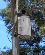
I was thinking it had to be more than 200A because there were two 150A breakers hanging off of it. The current setup was put in place in 1982. I can't see any markings on the meter base, but I've attached pictures of the transformer, meter, and wiring between meter and 150A panels.

-- Carl
 

Attachments

  • rps20170813_140353.jpg
    rps20170813_140353.jpg
    21.1 KB · Views: 57
  • rps20170813_134904.jpg
    rps20170813_134904.jpg
    46.3 KB · Views: 66
  • rps20170813_135914.jpg
    rps20170813_135914.jpg
    132.1 KB · Views: 77
OP
M

m32825

Well-known member
Joined
Jul 26, 2015
Messages
1,009
Location
Central FL
You may have issues with room and number of lugs in the transfer switch.

What are the ratings on the meter?

Picture of meter posted in reply to previous post.

I'm not married to the drawing, but I didn't want to rework the whole wall unless I had to. Sounds like regardless of what I do with a transfer switch, feeding three services from one source is going to need more wall space.

-- Carl
 
OP
M

m32825

Well-known member
Joined
Jul 26, 2015
Messages
1,009
Location
Central FL
How much space is there between the electric panels and the post with all the hoses.
(If less than 36" it's already a Code workspace violation.)

Hadn't even thought of that. It's 36" from the wall to the post. If it needs to be 36" from the front of the panel the post needs to move.

-- Carl
 
OP
M

m32825

Well-known member
Joined
Jul 26, 2015
Messages
1,009
Location
Central FL
If you're unable to locate suitable lugs you could install a junction box and install a three pole power distribution block fo this. Matter of fact this would be my first suggestion.

So the output of the transfer switch goes into the junction box then the distribution block fans it out to feed the three services. Do I have that right?

-- Carl
 
OP
M

m32825

Well-known member
Joined
Jul 26, 2015
Messages
1,009
Location
Central FL
Thanks to all for their suggestions and feedback. It's much appreciated and exactly why I posted, GJ rules!

Of course, it won't feel right until someone calls me an idiot and tells me I'm going to burn down my house! :)

-- Carl
 

mm08822

Well-known member
Joined
Jan 13, 2012
Messages
6,034
Location
NJ
The 1/0 (I'm assuming is copper) is only good for a 200A service.

Is the 1/0 shown feeding both 150A disconnects from the meter or does each disconnect have its own 1/0 from the meter?

150A is the confirmed rating of the cb in each exterior disconnect?

What are the load side conductor sizes connected to each exterior disconnect?

Do the two existing sub-panels have their own local main breaker - if yes, what are the sizes?
 

Bert_

Well-known member
Joined
Dec 24, 2016
Messages
9,771
Location
NW Iowa
The utility may have the service size on file. Otherwise someone could come out and tell you for sure.

If I had to guess I'd say that looks like a 200A socket. You have (2) 150A mains, which is OK as long as your total load is under 200A

I'll use RONK for example since I'm familiar with them. Their switches they can often be had with (4) hole lugs on the load side
 

wyliesdiesels

Well-known member
Joined
Aug 14, 2012
Messages
20,067
Location
Modesto, CA
I was thinking it had to be more than 200A because there were two 150A breakers hanging off of it. The current setup was put in place in 1982. I can't see any markings on the meter base, but I've attached pictures of the transformer, meter, and wiring between meter and 150A panels.

-- Carl

NEVER GOOD to assume.

Your meter has a CL200 meaning its 200a class.

I doubt its a 400a pan with a 200a meter.

The reason you can have (2) 150a main breakers is because of load diversity. Pretty rare and hard to use 100a+ on each panel at the same time much less 150a each.

Is this an all electric house?

What loads do you have?

Have you done a load calc?

Pic of transformer doesnt tell us anything because every PoCo sizes trany KVA demand differently. And physical size varies between manufacturers...

Mine undersizes them currently. My buddy who is a lineman told me the engineers use to oversize them...

I would start with a load calc. If after your calc you come up with needing more than 200a, you will have to have PoCo upgrade at least the meter (and you the pan as well as service entrance wire if overhead)....
 
Last edited:

mm08822

Well-known member
Joined
Jan 13, 2012
Messages
6,034
Location
NJ
NEVER GOOD to assume.

Your meter has a CL200 meaning its 200a class.

I doubt its a 400a pan with a 200a meter.

The reason you can have (2) 150a main breakers is because of load diversity. Pretty rare and hard to use 100a+ on each panel at the same time much less 150a each.

Is this an all electric house?

What loads do you have?

Have you done a load calc?

Pic of transformer doesnt tell us anything because every PoCo sizes trany KVA demand differently. And physical size varies between manufacturers...

Mine undersizes them currently. My buddy who is a lineman told me the engineers use to oversize them...

I would start with a load calc. If after your calc you come up with needing more than 200a, you will have to have PoCo upgrade at least the meter (and you the pan as well as service entrance wire if overhead)....

If that were a single 200A disconnect panel after the meter, the 1/0 is the component reduced for diversity (200*83% = 166A>170a) in the typical service config. Np, typical.
However, this service configuration could potentially (albeit very remote) be at 300a which is ~80% over the 1/0 ampacity. Seems too high. I've never seen anything like this for a single family unit. Multi-family and apartment building before individual metering, yes.
Is this a local practice? Not sure where any derating of these feeders is in the code for a single family unit post metering. The wiring from underground meter pan onward is all under the NEC scope.
 

toplessHO

Well-known member
Joined
Oct 20, 2014
Messages
14,079
Location
central florida
they give residential services a break on feeder sizes.
You have a gutter,perhaps its big enough,need to add all the wires up in it and see
IIRC an 8x8 is 2000MCM.
Perhaps using a feeder from MTS to a polaris lug will meet code.
Adding that additional 100A has put you over the threshold of a 200A meter.
You may be able to do this if you drop the breakers in subfeeds to 100A.
As stated you need to do a load calc.
 

wyliesdiesels

Well-known member
Joined
Aug 14, 2012
Messages
20,067
Location
Modesto, CA
If that were a single 200A disconnect panel after the meter, the 1/0 is the component reduced for diversity (200*83% = 166A>170a) in the typical service config. Np, typical.
However, this service configuration could potentially (albeit very remote) be at 300a which is ~80% over the 1/0 ampacity. Seems too high. I've never seen anything like this for a single family unit. Multi-family and apartment building before individual metering, yes.
Is this a local practice? Not sure where any derating of these feeders is in the code for a single family unit post metering. The wiring from underground meter pan onward is all under the NEC scope.

I was thinking each panel was fed by individual 1/0cu from the meter since as you point out 1/0 cu shared by (2) 150a panels could be overloaded.

We dont know how the panels are fed.

But then the load calc on each panel would have to be 100a or less so whats the point on 150a panel.. So yes this is funky.

OP can you open the wire gutter and snap a pic?
 
OP
M

m32825

Well-known member
Joined
Jul 26, 2015
Messages
1,009
Location
Central FL
OP can you open the wire gutter and snap a pic?

Working on it, ran out of daylight yesterday, left for work before daylight today.

Each of the boxes fed by the meter has a breaker inside that says 150A on it. The panels inside the house do not have their own disconnect breaker.

Each of the 150A breakers is fed with its own set of three 1/0 wires from the meter.

Single family, all electric home, on the large end.

Thanks for all the discussion, pictures later!

-- Carl
 

ard

Well-known member
Joined
Feb 16, 2015
Messages
4,391
Location
Sierra Foothills... California
Enough 'meter talk'

Lets turn to the 'generator side' of this project... ;)


OP want a 'transfer switch' that will have the following characteristics:

1. Normally distribute a 200 (or 300 or 400) amp input to three output lugs

2. When 'activated', disconnect the input, and connect the 50Amp twistlock to each of the three loads- one at a time.

Is there such a 'switch' or is this a multi-component switch panel?

Is it permissible to have only a 50A generator connected to potentially 100+ A of load?? Or is it necessary to have the generator supply a specific subset of circuits that have been load-calced to not exceed the generator capacity?
 
To avoid these ads, REGISTER NOW!

mm08822

Well-known member
Joined
Jan 13, 2012
Messages
6,034
Location
NJ
Working on it, ran out of daylight yesterday, left for work before daylight today.

Each of the boxes fed by the meter has a breaker inside that says 150A on it. The panels inside the house do not have their own disconnect breaker.

Each of the 150A breakers is fed with its own set of three 1/0 wires from the meter.

Single family, all electric home, on the large end.

Thanks for all the discussion, pictures later!

-- Carl

Ok, so now that is cleared up with the feeds to each disconnect from the meter. However, it raises the next question of the meter pan is currently undersized and you want to potentially add more load to it.
I think you are looking at a meterpan upgrade to 400A once you touch this service.
The service lateral could probably stay the same if the loads are really way below the 200A level. Your POCO will own this decision unless you can demonstrate a current issue with its existing size or your loads will significantly increase. Increasing it may be on your dime.

So now that you indicate an all electric home, it is time to understand the existing loads, sf of house, new loads proposed in garage, etc.
 

mm08822

Well-known member
Joined
Jan 13, 2012
Messages
6,034
Location
NJ
Enough 'meter talk'

Lets turn to the 'generator side' of this project... ;)


OP want a 'transfer switch' that will have the following characteristics:

1. Normally distribute a 200 (or 300 or 400) amp input to three output lugs

2. When 'activated', disconnect the input, and connect the 50Amp twistlock to each of the three loads- one at a time.

Is there such a 'switch' or is this a multi-component switch panel?

Is it permissible to have only a 50A generator connected to potentially 100+ A of load?? Or is it necessary to have the generator supply a specific subset of circuits that have been load-calced to not exceed the generator capacity?

I didn't get the impression OP wants to select which of the 3 loads would be connected. I'm thinking it was all or none.

On automatic stand-by systems, the gen must be sized for the connected load and/or have load management capability to keep the load within the gen's rated output.

Manual transfer panels (with interlock and metering) can get by with manual user intervention as well as input limiting the draw from the panel with a local gen feed cb. This is all done from one panel.

The OPs situation would be manual load management between between 3 disparate panels. This could be difficult if most loads were not shut off.
He will probably need a 50A cb as part of the permanent equipment to prove gen input wiring is protected. He would probably want to add metering to help manage gen loading.
 

toplessHO

Well-known member
Joined
Oct 20, 2014
Messages
14,079
Location
central florida
if you are selectively going to shed loads in both of those existing panels
you could replace the panels with split bus panels and refeed the generator side of panel
as the common on your MTS. Otherwise inspection dept will ask you to provide a big enough generator to feed the entire load.
 
OP
M

m32825

Well-known member
Joined
Jul 26, 2015
Messages
1,009
Location
Central FL
I didn't get the impression OP wants to select which of the 3 loads would be connected. I'm thinking it was all or none.

Yes, this is the plan. Every few years we have a few day outage. Since we're the only guys on the end of our line we are the last to get restored. For this scenario we have no problem manually shutting off all the breakers, cutting over to the generator, then turning on a marked subset of them. Small price to pay for being able to flush toilets and take a hot shower! :)

-- Carl
 
OP
M

m32825

Well-known member
Joined
Jul 26, 2015
Messages
1,009
Location
Central FL
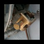
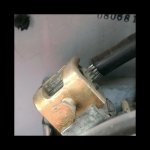
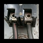
Pictures inside the meter base. Looks like the base is rated for 200A continuous, the incoming wires from the pole are aluminum (no size printed on them that I can see) and the wires running to the panels are 1/0 copper.

So how is it okay to plug 300A of stuff into a base rated for 200A?

-- Carl
 

Attachments

  • panelWiresInMeterBase.jpg
    panelWiresInMeterBase.jpg
    116.2 KB · Views: 34
  • serviceWireInMeterBase.jpg
    serviceWireInMeterBase.jpg
    97.8 KB · Views: 32
  • insideMeterBase.jpg
    insideMeterBase.jpg
    134.7 KB · Views: 28
OP
M

m32825

Well-known member
Joined
Jul 26, 2015
Messages
1,009
Location
Central FL
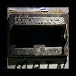
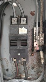
Pictures inside one of the panels fed from the meter base. Breaker is 150A, wires from base are copper, wires to service panels inside house are aluminum, no size markings visible.

-- Carl
 

Attachments

  • panelBreaker.jpg
    panelBreaker.jpg
    125 KB · Views: 23
  • panelLabel.jpg
    panelLabel.jpg
    148.2 KB · Views: 24
  • insidePanel.jpg
    insidePanel.jpg
    98.9 KB · Views: 34
  • wiresFromPanel.jpg
    wiresFromPanel.jpg
    118.6 KB · Views: 26

mm08822

Well-known member
Joined
Jan 13, 2012
Messages
6,034
Location
NJ
I believe (without looking it up) that split bus panels were outlawed by changes in the 1984 Code. :dunno:

I found a hit referencing 1984 as the outlaw date.

Even still, running a second feeder to each of the two panels would start to blow this job up and make it a really funky system.

OP, can you help explain the 2 panels: distances from meter, loads, etc.

Does the garage really need to come off of the meter or could it be a sub to one of the 2 existing panels?
Could the second panel become a sub off of the first panel (even if it means upgrading first panel)?

Really need a load calc for each panel, what you consider critical loads, and of course what is planned for garage.
 

wyliesdiesels

Well-known member
Joined
Aug 14, 2012
Messages
20,067
Location
Modesto, CA
Pictures inside the meter base. Looks like the base is rated for 200A continuous, the incoming wires from the pole are aluminum (no size printed on them that I can see) and the wires running to the panels are 1/0 copper.

So how is it okay to plug 300A of stuff into a base rated for 200A?

-- Carl

are there dual lugs in the meter pan?

I only see one copper wire under that lug...

And a load calc would answer your last question...
 

mm08822

Well-known member
Joined
Jan 13, 2012
Messages
6,034
Location
NJ
are there dual lugs in the meter pan?

I only see one copper wire under that lug...

And a load calc would answer your last question...

pic#2 in post#25 is line side of meter

pic#3 in post#25 is load side of meter with doubled-up wires in each single-wire lug.

Not liking that ground wire seemingly so close.
 

Bert_

Well-known member
Joined
Dec 24, 2016
Messages
9,771
Location
NW Iowa
I don't see any reason to upgrade this service unless the loads in your new building put you over 200A of actual load. Others seem to think that simply adding up breakers somehow equals load. It does not work that way, it is perfectly acceptable to have 3-400A worth of breakers on a 200A service as long as you have determined the load to be less than 200A. This is actually a common practice on much larger services. This does mean you should make sure your total load is less than the rating of the meter, but even if you had a single main you should do calcs anyway.

As far as a type or brand of transfer switch I've already mentioned Ronk, but there are other brands out there too. Ronk's 7215 would work well for a 200A service, load side has 4 hole lugs that fit 6-250 wire.
 

mm08822

Well-known member
Joined
Jan 13, 2012
Messages
6,034
Location
NJ
I don't see any reason to upgrade this service unless the loads in your new building put you over 200A of actual load. Others seem to think that simply adding up breakers somehow equals load. It does not work that way, it is perfectly acceptable to have 3-400A worth of breakers on a 200A service as long as you have determined the load to be less than 200A. This is actually a common practice on much larger services. This does mean you should make sure your total load is less than the rating of the meter, but even if you had a single main you should do calcs anyway.

As far as a type or brand of transfer switch I've already mentioned Ronk, but there are other brands out there too. Ronk's 7215 would work well for a 200A service, load side has 4 hole lugs that fit 6-250 wire.

Agreed, but OP's service is capable of drawing 300a thru a 200a pan. Your example (which is the typical install) limits the max draw thru the pan to 200A b/c of the single 200a panel main.

He would need a Service Entrance Rated version of the Ronk 7215 Xfer Switch in this current config.
 
Last edited:

toplessHO

Well-known member
Joined
Oct 20, 2014
Messages
14,079
Location
central florida
I want to see the lug specs in the meter can
as far as I can tell that lug isnt rated for multiple conductors
easy fix is to put a short piece of 4/0 to a Polaris lug
or redo all of that when you add the MTS.

you need to separate out the circuits you want to run off generator
and make a generator fed panel whose load is sized to the generator.
 

toplessHO

Well-known member
Joined
Oct 20, 2014
Messages
14,079
Location
central florida
I don't see any reason to upgrade this service unless the loads in your new building put you over 200A of actual load. Others seem to think that simply adding up breakers somehow equals load. It does not work that way, it is perfectly acceptable to have 3-400A worth of breakers on a 200A service as long as you have determined the load to be less than 200A. This is actually a common practice on much larger services. This does mean you should make sure your total load is less than the rating of the meter, but even if you had a single main you should do calcs anyway.

As far as a type or brand of transfer switch I've already mentioned Ronk, but there are other brands out there too. Ronk's 7215 would work well for a 200A service, load side has 4 hole lugs that fit 6-250 wire.[/QUOTE

160 amps not 200
 

Bert_

Well-known member
Joined
Dec 24, 2016
Messages
9,771
Location
NW Iowa
Agreed, but OP's service is capable of drawing 300a thru a 200a pan. Your example (which is the typical install) limits the max draw thru the pan to 200A b/c of the single 200a panel main.

Again his install is perfectly legal. My example was a 200A service nowhere did I mention a 200A main.

I agree he needs the service rated model which has a center off position rather than just Line or Auxillary.
 

mm08822

Well-known member
Joined
Jan 13, 2012
Messages
6,034
Location
NJ
I want to see the lug specs in the meter can
as far as I can tell that lug isnt rated for multiple conductors
easy fix is to put a short piece of 4/0 to a Polaris lug
or redo all of that when you add the MTS.

you need to separate out the circuits you want to run off generator
and make a generator fed panel whose load is sized to the generator.

See OP's Pic#1 in post 25(?). Label is partially obscured but can see max size of 250mcm. So yes larger single conductors from the meter pan could be bugged to hit both breakers with proper ampacity wire.

OP needs the loads calcs in order to provide enough info in order to understand best way to clean up this breaker mis-match and make gen tie-in easy. Current set-up is a problem.
 

mm08822

Well-known member
Joined
Jan 13, 2012
Messages
6,034
Location
NJ
Again his install is perfectly legal. My example was a 200A service nowhere did I mention a 200A main.

I agree he needs the service rated model which has a center off position rather than just Line or Auxillary.

You are right, it is legal per nec 230.90(A) exception 3 based upon calculated loads not exceeding se conductor rating (which would cover the meter pan).

This just seems like a problem waiting to happen as the future loads change and no one is looking any further than just plugging in more cb's to the local panel.
 
Last edited:

CJ7VFR

Well-known member
Joined
Jan 13, 2015
Messages
2,941
Location
Central New Jersey
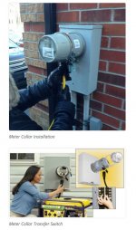
What about a Meter Collar transfer switch from the Utility company to hook up your generator to the entire house?

These are the type of power inlets that attach between your homes electrical meter and the meter receptacle. They have a twist lock receptacle on the bottom of the collar to make the connection from your generator water resistant, and they are one of the options that are endorsed by most electrical companies, since you buy them directly from the electrical company.

They are not cheap, but they are easy to install by your utility company, and they provide an inlet for the power from your generator that is distributed to all of your load centers and sub-panels. You would need to shut off and turn on the breakers in the panels as required during a power outage when you are running the generator.

Here is a picture of what I am talking about. Can someone chime in on whether or not these can be purchased for a generator putting out 50A 240V? I know they sell the ones that are for 30A 240V generators.

Jim
 

Attachments

  • metercollar.JPG
    metercollar.JPG
    69.1 KB · Views: 45
Last edited:

wyliesdiesels

Well-known member
Joined
Aug 14, 2012
Messages
20,067
Location
Modesto, CA
What about a Meter Collar transfer switch from the Utility company to hook up your generator to the entire house?

These are the type of power inlets that attach between your homes electrical meter and the meter receptacle. They have a twist lock receptacle on the bottom of the collar to make the connection from your generator water resistant, and they are one of the options that are endorsed by most electrical companies, since you buy them directly from the electrical company.

They are not cheap, but they are easy to install by your utility company, and they provide an inlet for the power from your generator that is distributed to all of your load centers and sub-panels. You would need to shut off and turn on the breakers in the panels as required during a power outage when you are running the generator.

Here is a picture of what I am talking about. Can someone chime in on whether or not these can be purchased for a generator putting out 50A 240V? I know they sell the ones that are for 30A 240V generators.

Jim

Most PoCos do not allow those but its something the OP can check into.
 
To avoid these ads, REGISTER NOW!
Top Bottom