To avoid these ads, REGISTER NOW!

MIG welding settings for body work?

MushCreek

Well-known member
Joined
Jan 14, 2015
Messages
9,834
Location
Upstate South Carolina
Maybe some of our more seasoned welders can help me get set up to do some automotive body work. All I have to work with is a big old 200A Lincoln MIG. I use CO2/Argon mix. Right now, I'm running .035 wire, which I assume is too big for sheet metal. I'll get a roll of .023 and some tips. Voltage? Amperage? Wire speed? I know the principle- clamp work, tack in place, keep adding spots until it's all connected. The good news is that it's an older Ford truck, with fairly thick sheet metal. The work I have to do on the bed will be even easier- 16 gauge. Any other pointers? Might it even be worth picking up a small cheap MIG like at HF, or can I do the job with mine?
 
To avoid these ads, REGISTER NOW!

dr_clyde

Well-known member
Joined
Jan 7, 2009
Messages
6,466
Location
Holland, MI
In my experience, you want to have the smallest wire you can handle, then run it hot enough to penetrate a no gap **** weld in one quick zap.

Don't try to run beads on bodywork. Just make hot tacks, moving around, allowing the metal to cool in between zaps.

If you try to run it cold, you'll end up putting in too much heat because it will take longer to melt the base metal. Hot and fast is key.
 

MP&C

Well-known member
Joined
Oct 21, 2009
Messages
4,405
Location
Leonardtown, MD
If you do need to jump down to a smaller size (I'm assuming your machine takes the 44 lb rolls?) try to either find some EZ Grind or Spoolarc 87HP, both an ESAB product. I think the 87HP (also known as ER70S-7) is only available down to a .030 size, well within the range for your sheet metal. Its major advantage is a higher manganese content for better wetting, ie: flowout than it's normal ER70S-6 counterpart. This equates to a flatter weld proud, for less grinding, easier planishing. If I had the choice I prefer the 87HP over the EZ Grind.

For initial set up on a MIG, I look first and foremost for FULL WELD PENETRATION while using a tight fitting **** weld, doing single tacks, or "dots". Next, in the case you do have too much heat as evidenced by a blowout, realize that first and foremost, the one thing you DO have is full weld penetration. The panel is "blowing out" because there is not enough filler wire going in for said amount of heat, hence the panel becomes the consumable wire. So before turning down the heat, add more wire feed speed until you no longer have blowout. Now you are where you can fine tune the settings but more importantly, fine tune the operator of the torch. Get out of your head that the heat control knob is the only thing that controls the heat that the panel sees. If you can increase the heat, increase the feed speed, and decrease the elapsed time of trigger pull, you will in essence have a full penetrating weld with less proud for less planishing needed, less grinding needed. More heat on the welder gives you a flatter weld. Less time on the trigger means the panel sees the same or less heat than with colder settings and longer trigger.

The colder your weld, the more proud you have on the top side of the panel, the less penetration you have in the panel. Once you have a cold joint, grind it off. You can pile on another 1/2" of blob, it will never penetrate properly.

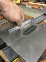
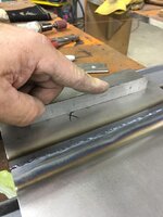
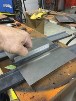
And because I have plenty of pictures, here's some test samples that I did. Side note..... you ran out of wire and just installed a new roll. Whether it's the same brand you used before or not, do some test samples if you are welding sheet metal. Always find out how everything works on a practice piece before jumping in on your good panels. Much of todays welding wire is made who knows where of who knows what. Get comfortable with it on scraps.. Also, note the pictures below show my test coupons in free air, just as your quarter panel on a car is. We don't do test coupons laying on a steel workbench because it is a heat sink and does not match the same conditions as the panels on your vehicle. Your practice should match those same conditions as your vehicle, so you are setting up the welder, fine tuning the settings, and fine tuning the operator...…all in the same conditions that exist on the vehicle... before you jump on your good panels


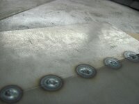
Installed .035 ER70S-7 in the machine, dialed in the settings for 3/16 thick steel, and ran some test welds... YES! HEAT SET FOR 3/16 STEEL! YES, .035 WIRE!!

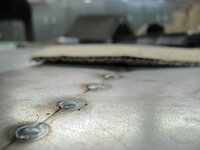
Note the minimal HAZ for the size of the weld dot, note the minimal build in the side profile shots...………..

Picture648.jpg

Front side....

Picture645.jpg

Picture646.jpg

Picture618.jpg


Rear side....

Picture647.jpg


The duration of trigger pull on these was less than a second, likely about 1/2 second. So the end goal of your practice should be welder setup, adjusting operator technique, and minimal proud/flatter welds having full penetration..


Lastly, on your truck bed floor I think you're going to find it is 19 gauge, no matter how thick it "seems". Those ribs add quite a bit of strength, and may make it appear to be thicker than it actually is..
 
Last edited:

MP&C

Well-known member
Joined
Oct 21, 2009
Messages
4,405
Location
Leonardtown, MD
Next, let's talk about gap vs. no gap.. If you've ever welded on both sides of one of those **** clamps, you see that the panel shrinks/pulls together such that the clamp can be difficult to remove. This is an indicator that the panel is pulling together and in the case of a crowned panel, ie: roof skin, hood, etc, it will be losing crown or creating a LOW..

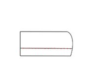
Part of the reason we use **** welds is to duplicate the original metal "flavor and feel" so that when someone looks at the backside of a panel or under the floor pans, they don't see a flange repair, or have to contend with ghost lines on exterior painted panels. We can effectively cut out damaged (rusty) metal, **** weld in a new section, planish/metal finish/filler as needed, and we can have an invisible repair that for all practical purposes should be a permanent repair. Part of the reason you see recommendation to use TIGHT **** welds, is that it eliminates open area that allows any panel movement, ie: as the weld shrinks, the panel pulls together. If the crown of our patch used to match prior to welding, weld shrinking along with the panel's pulling closer together (due to a gap) is going to pull in some of the crown. If it is a flatter crown, such as the middle of a quarter panel or top of a roof/hood, it is more noticeable as the crown in these areas is normally minimal/just enough to maintain the shape, and may result in oil canning. If it is a concave crown, such as a reverse where the wheel opening flare comes outward, then the weld seam has a tendency to pull outward as it shrinks. The following pictorial shows an exaggerated crown and gap primarily so you can see it in such a small area. But it shows what happens as weld shrinkage and panel movement pull at the surrounding area. In the bottom view, the red line depicts where the crown was originally.


weld%20gaps%20lose%20crown.jpg


With tight **** welds we do need to planish in order to remove any deformation caused by shrinking, and add some stretch back into the area. This should be the extent of our planishing effort, as the tightly fitting panels prevent the panel pull from adjacent areas (that a gap allows, resulting in loss of crown). In the case of any gappage around a patch, we would need to planish even more to add enough stretch to overcome this loss of crown, or add filler as needed.

In panels like hoods, trunk lids, and roof skins, that continual crown shape is what helps support the entire panel free from oil cans. Any low spot derived from a gap (panel pulls together) combined with weld shrinkage may serve as an interruption to that support, resulting in oil cans.


Looking at a quarter panel, one would expect in the case of a normal **** weld that the edges of the panels against each other will be a positive stop against any pull from adjacent areas. The only planishing we should need to do is to overcome any shrinking issues due to weld heat. If planishing is not done at all, one would expect the panel to show the following signs:


weld_gaps_lose_crown2.jpg


If your welds show any of those signs, then additional planishing is in order.
 

MP&C

Well-known member
Joined
Oct 21, 2009
Messages
4,405
Location
Leonardtown, MD
The following should help in understanding warpage.


I hear people all the time suggesting to only use the bare minimum amount of a patch panel needed to repair the rust. I prefer to look at it another way, For example, most rocker panels have an outward crown that, if we cut out a patch for the front 1/3 only, we are left with a vertical seam. The shrinking that will indeed take place is going to give us a nice valley right at the vertical weld seam. So IMHO, it makes more sense to install a FULL rocker panel, where most are installed with spot (plug) welds at top and bottom flanges. Without using a vertical **** weld seam that you'd need for a partial patch, there is virtually no warpage at all in installing the full panel.

For any other patches, (quarter panel, door corners, etc.), I worry less about using the least amount of patch possible, and more about putting a weld seam where you do have access to planishing. Additionally, a half height quarter patch puts your weld seam in the middle of a low crown area for a guaranteed warpfest. Using a taller quarter (even if not the OEM full height) puts the weld seam up higher where the profile usually has a higher crown, which helps to control the warping a bit better. So if given the choice here, I am using the tallest quarter available and putting the seam:

1) where I have access for planishing

2) in a higher crown area to help control warping

3) near body crease to help control warping (keeping enough distance for dolly placement).

Other body panels would follow same 1-3 considerations in that same order.

For trimming, I try to keep absolute tight joints and if using MIG, set the welder hotter, adjust wire feed faster if it tends to blow holes, and control heat with shorter length of time on the trigger pull. first and foremost, we need to insure full weld penetration, so some practice on scraps of same material thickness and clamped in mid air to simulate what is on the car. (metal welding table is a heat sink) To further explain gap vs no gap, anything welded is going to shrink when the weld cools. If you have a gap, the weld will pull the panels together as it cools, and each subsequent weld will pull it that much closer together. So if your panel had been trimmed correctly, now you have low areas being put in as the panel is moving. If the new patch is trimmed for a tight joint, then it will still shrink, but you will only need to planish to overcome weld shrinkage, and should not have panels moving together creating low areas. In essence, it will still need planishing as would a gapped joint, but with no gap it should remain more consistent where any planishing required is also consistent. With panels pulling together in a gapped situation, you will have differing planishing requirements based on how much the panel pulled in that particular area. Hope my rambling makes sense.


I had done some test welds a few years back and I think the pictures taken will help out in understanding the weld location and shrinking. Where these welds were done using the TIG, it still does well to show the benefits of choices 1, 2, and 3 as shown above. Here's the tacking process, and as said in video, amperage is set at 70. Based on 18 gauge thickness this should have been about 45, but as we also do with MIG "dot" welding, higher amperage and less elapsed time on trigger pull = flatter welds, less HAZ.


Note minimal weld size, minimal HAZ with the higher amperage, shorter burst...


IMG_1948.jpg


Patches started out flat and for the most part remained so..


IMG_1963.jpg


IMG_1964.jpg


Adding a weld pass we are quick to see some distortion...


IMG_1966.jpg


IMG_1965.jpg


Examining this further, even though we have absolutely tight gaps for less instance of the panels pulling together, we still see distortion.. This is your typical weld shrinkage as the weld cools. Note in the next picture the panel is still fairly flat along the edges (red line), some shrinking at the weld (yellow arrows) and show a dramatic pucker between the two. Note that the weld has yet to be planished, so the weld shrinkage is pulling the metal alongside it together, the areas unaffected by heat remain largely unchanged (red line) and the area between the two are forming a bulge due to these differing forces. Here we address the problem, not the result. Planish out the weld to stretch it in length and the bulge will disappear. Don't make a habit of chasing the result, a shrinking disc on the bulge is not the correct resolution; if this were a crowned panel that action would be causing a severe low area for a greater chance of oil cans.


IMG_1965A.jpg


Referring back to an earlier statement I made on weld location:


......let's try this same scenario using a crowned sample near a body crease so we can take advantage of all 3 choices...

IMG_1986.jpg


Weld pass....


IMG_1991.jpg


IMG_1999.jpg


IMG_1998.jpg


Here we can see how the weld location and panel features (crown, body crease) helped to control and limit any warping effects. The weld will still need planishing to restore the crown of the center bead, as no doubt it has pulled in slightly, but this is hands down a dramatic improvement over the flat "patches" we did the first time. This shows how these features in your body panels can help out in controlling weld distortion, so take advantage of these in weld location and leave the limiting of panel size as your absolute last consideration.
 

MP&C

Well-known member
Joined
Oct 21, 2009
Messages
4,405
Location
Leonardtown, MD
Now with those formalities out of the way, I'll show what I do for MIG welding sheet metal...


Let's say we are installing a lower door skin to repair some rust. The repair panel has been trimmed for zero gap (or as close as we can), then the panel is tacked on, starting at one end, and working PROGRESSIVELY TOWARD the other. Don't skip around from one end to the other as you have a greater chance of misalignment in that you may have more metal trapped on one side than the other. When you get down to the final tacks this can result in a buckle from the excess metal once the welds bring it together. So I start at one end, tack, move an inch or so, align the panels together, make another tack, repeat. This insures the panels are correctly aligned as you work progressively from one end of the weld seam to the other.


doorpatchtacked.jpg


Once done with the last tack, go back to the beginning and use a hammer and dolly to planish each weld dot, working in the same start to finish pattern. Now go back to the beginning and use a 3" cutoff wheel to grind the weld dots down to just above flush, both FRONT AND BACK, as this gets the weld prouds out of the way for both planishing the next sets of weld dots, and also removes all the excess weld that is going to change the heat load. A weld bead can be up to 4-5 times the thickness of the parent metal, grinding it down keeps the effective metal thickness the same throughout. I grind to just above panel height for a weld seam like this, and final cleanup with a 3" roloc sander will be used at the end to dress the seam to the parent metal. Here's a video that shows the grinding process, but as this is a plug weld it is dressed immediately following. Again, a full weld seam gets dressed at the end. Much less chance of taking away too much metal.


Now that those welds are down and out of the way, let's add the next set. Here I'll overlap the last set of welds by about 1/3 to 1/2. Whatever the distance of your overlap, keep it consistent throughout.


doorpatchsecondtack.jpg


This method helps to eliminate any missed areas of weld. Again, start from the same spot you did before, overlap the first weld dot where you started, go the the next, overlap, repeat, until you get to the end. Then go back and repeat the planish from start to finish, then grind weld dots from start to finish, both FRONT AND BACK, and then repeat the overlap process again. Keep repeating the process until the weld seam has been finished, then use a roloc sander to dress the little bit of remaining weld to flush with parent metal, both front and back side.


If this sounds like a slow, monotonous process, yes it is. This promotes consistency in the welding process, from fitup through to final welds dressed. At no point is it necessary to cool the welds, by the time planishing and grinding are complete, the welds on the panel are plenty cool to the touch. Any artificial cooling serves no purpose.
 

Copymutt

Well-known member
Joined
Sep 3, 2016
Messages
3,408
Location
Colorado
Lots of experience posted above. Certainly more talent than I have. Just a comment from a current project. I needed to add 2’ to a length of 16 ga. C channel. Looks were not important. As I was already set up w/ flux core & my CO2 was connected to my beer kegs, I tried .035. Was amazed how well it worked and no warp.
For bodywork Ive found backing up the weld w/ 12 or 14 ga copper helps absorb heat and prevent warp.
 
OP
M

MushCreek

Well-known member
Joined
Jan 14, 2015
Messages
9,834
Location
Upstate South Carolina
That is a great lesson! Thanks so much for posting all of that. Body work will be door skin repairs on the outside corners, floors (not gonna get as fussy there) and filling a bazillion trim holes. When I've done trim holes in the past, I've back them with a piece of copper. On the bed, it will be all new 16 ga. steel, and mostly I'll be spot welding (but with the MIG) What I've seen done is to drill holes in one piece, then weld a little rosette in the hole to simulate a true spot weld.

In looking at my welder, a Lincoln SP-200, I discovered that it does have timers for stitch welding and spot welding. I hope the timer works; I've never tried it. There's a big chart inside the door that I never noticed before. On the chart, they show using .035 wire, even for sheet metal. I have tons of stuff around here to practice on, so I guess I'll start at their recommended settings and see what happens. I've only used the machine to do occasional structural stuff like angle and channel.

Interesting point about using a tight fit, rather than using the clamps. I always thought the clamps were the best set-up, but they do make a pretty large gap. A lot of the repairs I need to do won't be accessible from the back side, so I'll just have to do the best I can. The door skins are going to be blocked by the inner door panel, which is fine. I got some rust-through from mud being trapped under the trim. I also have a couple spots on the underside of the hood that are completely blocked by inner panels. I'll just cut out until I hit solid metal, and make a patch. It's a flat area, and out of sight unless the hood is open, so it will mostly be to try to stop further rust. I'll have to figure out some way to get some magic goo inside of there to try to arrest the rust.
 

joe_padavano

Well-known member
Joined
Feb 26, 2011
Messages
1,788
Location
Northern VA
In my experience, you want to have the smallest wire you can handle, then run it hot enough to penetrate a no gap **** weld in one quick zap.

Don't try to run beads on bodywork. Just make hot tacks, moving around, allowing the metal to cool in between zaps.

If you try to run it cold, you'll end up putting in too much heat because it will take longer to melt the base metal. Hot and fast is key.

^^^THIS! I've used this technique with success, but now I have a TIG, which is the better choice. Bottom line is that you must go over the tacks with hammer on dolly to stretch the metal back out after the tacks cool. This removes the shrinkage distortion.
 

22george

Well-known member
Joined
Jan 26, 2011
Messages
1,637
Location
SW Ohio
Thanks again for your explanations. They are very helpful. I printed out this latest welding explanation to take to the pole barn to keep handy as reference material. As l go long periods of time between welding l need to refresh my memory so this will really help.
 
To avoid these ads, REGISTER NOW!

Aaron_W

Well-known member
Joined
Feb 6, 2018
Messages
2,940
Location
Northern California
Wow, just posting to say thank you to Robert.

I have some rust repair to do on some old trucks (mostly flat panels) and this is great information, stuff I didn't even know I didn't know.
 

dennis111

Well-known member
Joined
Sep 27, 2011
Messages
60
Location
Amish Wonderland of Central Pa
Robert, thank you for the above material. I have learned a lot of neat tricks from you. Using your techniques has helped my autobody welding tremendously.

Curious if you have a source for ER70S-7 on smaller reels, such as the 12.5lb that Lincoln sells in -6? What would be your preferred diameter for 20ga sheets of this -7 grade wire?
 

MP&C

Well-known member
Joined
Oct 21, 2009
Messages
4,405
Location
Leonardtown, MD
To my knowledge the ESAB 87HP is only available in the larger rolls, and only down to .030 diameter. (Still well within the heat range of 18 gauge sheet metal).
 
OP
M

MushCreek

Well-known member
Joined
Jan 14, 2015
Messages
9,834
Location
Upstate South Carolina
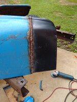
I started doing some repair work today. I have a pair of steel stepside fenders in need of help. The bottom 3" or so is basically gone. I bought patch panels and got one of them done today. I had to use panel clamps, as the patch panels are a poor approximation of the actual shape. Not fun trying to fill in that gap, but I got it done. Not perfect, but putty and paint make a welder what he ain't. I started with the fenders because they're quite thick, so more forgiving. I really don't have much to lose, either. They were ready for the scrap pile, and I managed to bring them back, at least good enough for a work truck.

While we're talking about putty- Is there a better product than Bondo? Maybe some kind of epoxy putty or something? I've never had good long-term success with Bondo, although it is cheap and easy.
 

SteveH-CO

Well-known member
Joined
Aug 29, 2014
Messages
283
Location
Southern Colorado
A great way to get started is to work on the annoying holes in the floor pan and hidden areas, and develop a lot of technique there. Then, move on to visible body panels and trickier work.

Also, after you think you're done welding, in a dark room, shine an intense light behind your welded seam and look for pinholes in between the welds. There are sure to be some, and if you apply filler (of any type) and water gets behind it, you can kiss it goodbye, rust-wise. Keep welding and grinding until you have a solid, watertight/light-tight seam.
 

MP&C

Well-known member
Joined
Oct 21, 2009
Messages
4,405
Location
Leonardtown, MD
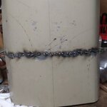
My welding looks more like a bag of marbles than a stack of dimes, but it's sturdyIMG_20210612_085917368_BURST000_COVER.jpg


What does the back side look like? It may be sturdy now, but you need to dress the welds flush with the panel. Do you have full penetration on the welds?
 
OP
M

MushCreek

Well-known member
Joined
Jan 14, 2015
Messages
9,834
Location
Upstate South Carolina
Yes, I ground it down, and it's still solid. I welded the back side, too, and there's no need to grind it down. It's not a very good set of fenders anyway; this is partly just for practice. I can buy brand new steel fenders for $350 a piece, so this is barely worth doing, except for the practice aspect. I'm going to strip the fenders to bare metal, as they have about ten coats of paint on them, then start filling the various dents. We'll see how they come out when they're all finished. I **** at body work, but I'm trying to get better at it.

I tried to planish the welds with a body hammer and dolly, but they're extremely hard. Do they need to be annealed with a torch?
 

Los_Control

Well-known member
Joined
Jul 28, 2020
Messages
191
Location
West Texas
Here's a couple of pics. My welding looks more like a bag of marbles than a stack of dimes, but it's sturdy.IMG_20210612_090113760_HDR.jpgIMG_20210612_085917368_BURST000_COVER.jpg
I looked at that and thought maybe I welded it :giggle:
More heat, and if it blows out, more wire feed speed.
Thats sounds like good advice. Just following along here as I am practicing/learning mig myself. have a 190 mp with argon mix.
Always think I need to turn down the heat, I probably should be turning it up.
 

Attachments

  • 0615210652a.jpg
    0615210652a.jpg
    495 KB · Views: 48
OP
M

MushCreek

Well-known member
Joined
Jan 14, 2015
Messages
9,834
Location
Upstate South Carolina
From what I hear, the ER70S-7 wire would give flatter beads, but I can't find it in a smaller roll than 44 lbs. considering it has taken me 5 years to go through 11 lbs. of -6, there's no sense in me buying a huge roll of -7.
 

metlmunchr

Well-known member
Joined
Sep 10, 2011
Messages
1,280
Running hotter will make the weld deposit softer and more malleable as well as making it lay down flatter. Running straight CO2 will also make the deposit softer for the same machine settings as CO2 makes the weld hotter as compared to C25. The higher the percentage of argon in the shielding mix, the harder the deposit will be.

Hobart explains this in their literature on mig wire, but they don't explain why it happens. It has to do with the manganese in the wire and the freeze rate of a hotter versus a colder weld where the Mn's ability to harden steel can do its thing.
 

dffay

Well-known member
Joined
Jul 9, 2015
Messages
437
On occasion I’ve just welded the inside, most recently filling holes in a firewall. 100% penetration meant that I had very little to smooth out on the ‘show’ side. What little warpage I had put the high side on the outside making hammer a dolly work so much easier.

Miller and Hobart have very helpful freebie apps for the cell phone that give very good starting parameters.
 

MP&C

Well-known member
Joined
Oct 21, 2009
Messages
4,405
Location
Leonardtown, MD
From what I hear, the ER70S-7 wire would give flatter beads, but I can't find it in a smaller roll than 44 lbs. considering it has taken me 5 years to go through 11 lbs. of -6, there's no sense in me buying a huge roll of -7.

Robert, thank you for the above material. I have learned a lot of neat tricks from you. Using your techniques has helped my autobody welding tremendously.

Curious if you have a source for ER70S-7 on smaller reels, such as the 12.5lb that Lincoln sells in -6? What would be your preferred diameter for 20ga sheets of this -7 grade wire?

McMaster carries it in the 11 lb rolls:

 
To avoid these ads, REGISTER NOW!
Top Bottom