Woo-Hoo!! Slung out some chips tonight!! I had basically a ruined Seadoo head. I set it up and indicated it, had to shim one side .020", then I took a cut with a 3/4" 4 flute end mill at 325rpm. That's fast in low gear on my Grizzly. It's a rough looking cut but doesn't feel that bad running a finger over it. Then I got excited while playing with power feeds and DRO and missed the section between the domes...

. I also put in a cutter I made to recut the damaged squishband.....worked like a champ

. I have a 2 flute end mill, and also another flycutter and tool steel. I might just grind a tip into that steel and reface the head with that flycutter. Anyway, I had some fun learning a bit about my mill.
Things to note.....
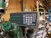
-DRO sensors are plugged into the wrong holes, knee is x, etc.
-Knee power feed only works when variable knob is cranked wide open.
-Quill feed engaged makes the micro wheel spin but the quill doesn't move. Engage lever under the wheel feels stiff and doesn't act like it wants to stay engaged.
-If you speed up the left to right (X?) table feed over half speed the table makes a stuttering/vibration noise.


") )
)
 . So I'm betting I'll figure out how to do almost anything on this mill.