To avoid these ads, REGISTER NOW!

Milling set up question

WhoWhatNow

Well-known member
Joined
Feb 22, 2011
Messages
1,891
Location
Collegeville, PA
I need to mill the center of a roller chain sprocket gear out. I am doing this on my manual Bridgeport with a rotary table (no DRO). My question is how I go about finding the center of the gear so I can mill the center out. I am sure this is a simple exercise for the machinists here but his is the first time I am using the rotary table so any help is appreciated.
 
To avoid these ads, REGISTER NOW!

WILD-BILL

Well-known member
Joined
Dec 10, 2011
Messages
875
Location
Brook Park Oh
You can get it close by using something that fits the bore of the gear snugly and chucking that into the chuck and move the part until the piece slids down into the bore freely.

To get it dead nuts, you need to sweep the bore with a coaxial indicator or a DTI.
 

no704

Well-known member
Joined
Apr 27, 2016
Messages
5,229
Pics of the gear would help. Sweep in with an indicator. Just like finding 0 on the rotary table.
 
OP
W

WhoWhatNow

Well-known member
Joined
Feb 22, 2011
Messages
1,891
Location
Collegeville, PA
Thanks guys. Mr. Pete had a great video on it. I'm going to have to get creative with clamping the gear to the table, but I think I have an idea on that. No more shop time tonight so I'll have to try it tomorrow.

9807eeaa022fe00491dafe342c7536dc.jpg
 

Attachments

  • 9807eeaa022fe00491dafe342c7536dc.jpg
    9807eeaa022fe00491dafe342c7536dc.jpg
    386.3 KB · Views: 0

Guster

Well-known member
Joined
Mar 11, 2012
Messages
1,543
Location
Auckland, New Zealand
Probably would have run that operation with a boring head instead. Bit more control to sneak up on your dimension and no problems with work holding in this case.
 

lukedwag

Well-known member
Joined
Aug 5, 2007
Messages
202
Mount the gear on the Chuck and then hold the tool on the table. Use it like a lathe
 

A_Pmech

Well-known member
Joined
May 8, 2007
Messages
8,002
Location
IL
Remember that you must make the axis of gear concentric with the axis of the rotary table, NOT the machine spindle, to bore the gear correctly.

An indicator mounted in the spindle resting on the gear bore while rotating the rotary table with the worm disengaged is sufficient.
 

matt_i

Well-known member
Joined
Mar 14, 2008
Messages
10,741
Location
SE Michigan
Probably would have run that operation with a boring head instead. Bit more control to sneak up on your dimension and no problems with work holding in this case.

This would be my thought also, if you desire a precision fit/size.

Also, a lathe would do the job quickly and more reliably...but understand you might not have one.
 

m32825

Well-known member
Joined
Jul 26, 2015
Messages
1,009
Location
Central FL
... a lathe would do the job quickly and more reliably...but understand you might not have one.

Educate me on this. How would you securely mount the gear on the lathe? Same question for the earlier suggestion to mount it on the chuck. Not taking issue with the approach, just trying to learn a new trick. Thanks!
 

Guster

Well-known member
Joined
Mar 11, 2012
Messages
1,543
Location
Auckland, New Zealand
Educate me on this. How would you securely mount the gear on the lathe? Same question for the earlier suggestion to mount it on the chuck. Not taking issue with the approach, just trying to learn a new trick. Thanks!

If it fits the lathe, one option and probably the fastest would be a square piece of flat stock with two or more holes matching the bolt holes in the gear. Chucked up in a four jaw and then dialed in both running concentric to the hub and planar to the surface of the gear. Bore away...

Plenty of other options.
 

ER70S-2

Well-known member
Joined
Jan 2, 2015
Messages
805
Probably would have run that operation with a boring head instead. Bit more control to sneak up on your dimension and no problems with work holding in this case.

Definitely. Clamp it to the table, center the spindle with a DTI, and bore it. You could have been done a long time ago. This is not a job for a rotary table IMO.
 

m32825

Well-known member
Joined
Jul 26, 2015
Messages
1,009
Location
Central FL
Thanks for the tips, Guster & ER70S-2! I get to play in the machine shop enough to know that half the job is figuring out the right way to fixture things. Now I've got something new to try!

-- Carl
 

Doug Arthurs

Well-known member
Joined
Dec 1, 2012
Messages
1,137
Location
Ontario
I would bolt that to the table and use a boring head as well. Too much work getting the rotab set up and then the gear concentric with the rotab. Plus my rotab is way too heavy I avoid it as much as possible. If you must use the rotab then bolt a block of steel or alum to it and drill and tap holes to bolt the gear down to the block.
 

Doug Arthurs

Well-known member
Joined
Dec 1, 2012
Messages
1,137
Location
Ontario
You are probably about to tell me you don't have a boring head. I get it. But you have bought a Bridgeport so you need to start thinking like a Bridgeport owner.

In the past a job would come along and you would think "how can I do this with the tools I have." This is the old way of thinking. Now that you have a mill you need to revise your way of thinking.

The new milling machine owner way of thinking is "what new tooling, accessory or cutter can I buy to accomplish this job". Once you conform to this life will get better. Stop resisting. When you get to the point where you can no longer find new tooling to accomplish the job, you know you have arrived at the point where you need to upgrade your mill to one that is Less worn, or has more bells and whistles.
 
To avoid these ads, REGISTER NOW!

buildyourown

Well-known member
Joined
Jan 8, 2010
Messages
185
Use a pair of kant twist clamps to hold the gear down to a bar of aluminum that fits in your vise. Dial the hole in with a test indicator. You should have one. Its one of the most common setup tools for a manual or cnc machinist. Gets your vise square, finds holes, edges, plates, centers of shafts, etc.
Then use a boring head to make your hole. You can get them pretty cheap on ebay.
 

manwithtools

ALLIANCE MEMBER
Joined
Aug 24, 2015
Messages
14,063
Location
Lebanon, TN
You are probably about to tell me you don't have a boring head. I get it. But you have bought a Bridgeport so you need to start thinking like a Bridgeport owner.

In the past a job would come along and you would think "how can I do this with the tools I have." This is the old way of thinking. Now that you have a mill you need to revise your way of thinking.

The new milling machine owner way of thinking is "what new tooling, accessory or cutter can I buy to accomplish this job". Once you conform to this life will get better. Stop resisting. When you get to the point where you can no longer find new tooling to accomplish the job, you know you have arrived at the point where you need to upgrade your mill to one that is Less worn, or has more bells and whistles.

LOL, this is so true. I just about split my sides reading this. :)
 
OP
W

WhoWhatNow

Well-known member
Joined
Feb 22, 2011
Messages
1,891
Location
Collegeville, PA
Thanks for all the help guys.

Just a few pictures of what I did to move this project along.

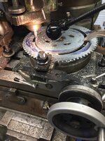
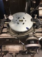
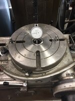
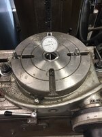
Since this was the first time using a rotary table, I did not have any T-nuts. So I had to make a pair. Not sure what type of steel I pulled out of the scrap bin, but I couldn’t tap them to save my life. The studs got welded so I could move on to the actual task at hand.

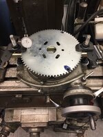
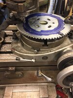
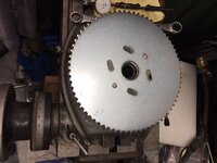
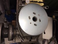
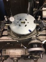
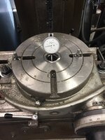
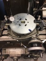
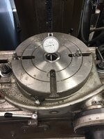
I got the table centered and then used little creative clamping to keep the gear off the table surface (I love Unistrut). The gear was centered next. I did a quick turn without turning the mill on to make sure everything was positioned correctly. Everything went pretty smoothly. And it fits perfectly. I welded a few studs to the gear and then the studs to the blower shoot.

So everything is together, but it isn’t working properly unfortunately. It rotates smoothly without the chain attached but once the chain is placed on both gears, it gets very hard to turn and the hydraulics can’t move it. Not sure exactly what is wrong yet. I am guessing something is misaligned.

I do actually have a boring head. Learning to use that will be for the next project.
7a1586f2667af54612ce751b29c94061.jpg

1a0012ab5b2abe75eb64fc2537a9d6f1.jpg

a2a70583ebc5ce3665554199616b1311.jpg

a7a3f806ce7347f30e4167e0f95c1bfd.jpg

b382f4ca2f93afc9254b88e6f643e95c.jpg

2ee339b9bd3a9c1d7cacdcb203ff60fc.jpg
 

Attachments

  • 2ee339b9bd3a9c1d7cacdcb203ff60fc.jpg
    2ee339b9bd3a9c1d7cacdcb203ff60fc.jpg
    338.9 KB · Views: 0
  • b382f4ca2f93afc9254b88e6f643e95c.jpg
    b382f4ca2f93afc9254b88e6f643e95c.jpg
    490.6 KB · Views: 0
  • a7a3f806ce7347f30e4167e0f95c1bfd.jpg
    a7a3f806ce7347f30e4167e0f95c1bfd.jpg
    426.9 KB · Views: 0
  • a2a70583ebc5ce3665554199616b1311.jpg
    a2a70583ebc5ce3665554199616b1311.jpg
    409.2 KB · Views: 0
  • 1a0012ab5b2abe75eb64fc2537a9d6f1.jpg
    1a0012ab5b2abe75eb64fc2537a9d6f1.jpg
    369.5 KB · Views: 0
  • 7a1586f2667af54612ce751b29c94061.jpg
    7a1586f2667af54612ce751b29c94061.jpg
    404.4 KB · Views: 0
OP
W

WhoWhatNow

Well-known member
Joined
Feb 22, 2011
Messages
1,891
Location
Collegeville, PA
Thanks for all the help guys.

Just a few pictures of what I did to move this project along.

Since this was the first time using a rotary table, I did not have any T-nuts. So I had to make a pair. Not sure what type of steel I pulled out of the scrap bin, but I couldn’t tap them to save my life. The studs got welded so I could move on to the actual task at hand.

I got the table centered and then used little creative clamping to keep the gear off the table surface (I love Unistrut). The gear was centered next. I did a quick turn without turning the mill on to make sure everything was positioned correctly. Everything went pretty smoothly. And it fits perfectly. I welded a few studs to the gear and then the studs to the blower shoot.

So everything is together, but it isn’t working properly unfortunately. It rotates smoothly without the chain attached but once the chain is placed on both gears, it gets very hard to turn and the hydraulics can’t move it. Not sure exactly what is wrong yet. I am guessing something is misaligned.

I do actually have a boring head. Learning to use that will be for the next project.

53a88e7dbd129aea616316ae5509a009.jpg

d108b84001e1c3d9732ddfe42a3c4bfc.jpg

5957a0901340724ccdcada478231034a.jpg

115d66010fbafb1fe5322dc34d6fecb5.jpg

a970efe8a36b8e030c30ede3065c39d8.jpg

7d1f96b7ec03a29b75e92d6251111ec1.jpg
 

Attachments

  • 7d1f96b7ec03a29b75e92d6251111ec1.jpg
    7d1f96b7ec03a29b75e92d6251111ec1.jpg
    342.2 KB · Views: 0
  • 53a88e7dbd129aea616316ae5509a009.jpg
    53a88e7dbd129aea616316ae5509a009.jpg
    404.4 KB · Views: 0
  • d108b84001e1c3d9732ddfe42a3c4bfc.jpg
    d108b84001e1c3d9732ddfe42a3c4bfc.jpg
    369.5 KB · Views: 0
  • 5957a0901340724ccdcada478231034a.jpg
    5957a0901340724ccdcada478231034a.jpg
    409.2 KB · Views: 0
  • 115d66010fbafb1fe5322dc34d6fecb5.jpg
    115d66010fbafb1fe5322dc34d6fecb5.jpg
    490.6 KB · Views: 0
  • a970efe8a36b8e030c30ede3065c39d8.jpg
    a970efe8a36b8e030c30ede3065c39d8.jpg
    338.9 KB · Views: 0
OP
W

WhoWhatNow

Well-known member
Joined
Feb 22, 2011
Messages
1,891
Location
Collegeville, PA
Th chain was slack for the last picture.


bbf32f3d4243b394e9f93996926b1000.jpg

dd884b53d3ad4417860e91a45348498b.jpg


986b01149cd22fb31e8f750cd8ba4e7c.jpg
 

Attachments

  • 986b01149cd22fb31e8f750cd8ba4e7c.jpg
    986b01149cd22fb31e8f750cd8ba4e7c.jpg
    358.3 KB · Views: 0
  • dd884b53d3ad4417860e91a45348498b.jpg
    dd884b53d3ad4417860e91a45348498b.jpg
    527.4 KB · Views: 0
  • bbf32f3d4243b394e9f93996926b1000.jpg
    bbf32f3d4243b394e9f93996926b1000.jpg
    424.6 KB · Views: 0
OP
W

WhoWhatNow

Well-known member
Joined
Feb 22, 2011
Messages
1,891
Location
Collegeville, PA
Th chain was slack for the last picture.


7e4a19de99da88f3275ff38322a76c9e.jpg

6e52e162f504359305fbe83f720479e7.jpg

fa0d44474c13030d3b92937f98a75d86.jpg
 

Attachments

  • 7e4a19de99da88f3275ff38322a76c9e.jpg
    7e4a19de99da88f3275ff38322a76c9e.jpg
    424.6 KB · Views: 0
  • 6e52e162f504359305fbe83f720479e7.jpg
    6e52e162f504359305fbe83f720479e7.jpg
    527.4 KB · Views: 0
  • fa0d44474c13030d3b92937f98a75d86.jpg
    fa0d44474c13030d3b92937f98a75d86.jpg
    358.3 KB · Views: 0

helterskelter

Well-known member
Joined
Mar 26, 2010
Messages
296
It's hard to tell from your pictures but it looks like only one small clamp is holding the enter of the gear? Your endmills will be much happier if you had secured it more rigidly.

Also this is definitely better as a lathe job if you've got one.
 
OP
W

WhoWhatNow

Well-known member
Joined
Feb 22, 2011
Messages
1,891
Location
Collegeville, PA
It's hard to tell from your pictures but it looks like only one small clamp is holding the enter of the gear? Your endmills will be much happier if you had secured it more rigidly.

Also this is definitely better as a lathe job if you've got one.


I used a clamp during the final part of the cut to make sure the center section did not move after being cut free. The gear is held on the perimeter (at 12 and 6 in the picture.)

My lathe is only an 8” so it was too small for this job.
 

ER70S-2

Well-known member
Joined
Jan 2, 2015
Messages
805
That's what you wanted to do? You should have said that you wanted to take out almost all of the center! I was imagining that you only wanted to open up the center hole a little bit. What you did wasn't really a job for a boring bar as I originally thought. Putting the gear on a faceplate on a lathe would have probably been a little easier, but what you did was fine!
 

NitroShark

Well-known member
Joined
Jan 8, 2010
Messages
518
Location
Greenville, SC
I've bored lots of sprockets with a manual Bridgeport.. For that job with your setup No indicators are needed just a plate of aluminum bolted to your rotary table (face plate).

Going off the sprocket pitch diameter would of been the most accurate but in your case I would have done this using the sprocket OD as a reference.


1) Bolt aluminum face plate to rotary table.
2) counter bore the plate 3/4 thicknesses of your sprocket using just an endmill.
3) clamp sprocket down in counterbore.
4) using endmill---now just cut out you socket bore with the rotary table as you did before.
 

homebuilt burner

Well-known member
Joined
Dec 8, 2014
Messages
1,763
Location
central Wisconsin
Good job. Looks like you solved your own problem. It is always good to hear others ideas as sometimes we overlook the obvious. The more machining I do the more I find I don’t know.
 

66cj225

Well-known member
Joined
Nov 4, 2011
Messages
332
Location
NH
By its title the scope of this project is limited but the next thought should be the radial outside and inside cuts for the guard that protects you and your grandchildren from the pinch points. Hydraulics aren't really forgiving.
 

OccupantRJ

Well-known member
Joined
May 15, 2009
Messages
11,221
Location
Eastern North Carolina
Check your flow control valve. The way you have it on one side of the hydraulic motor likely would have speed of movement in one rotation direction, but almost lock up in the other direction as this type valve usually controls flow in one direction only. It would need to be installed before your directional valve to control the speed of the motor equally in both directions.

Nice work on the sprocket. Ya done good.
BTW, your mill is a 1957 model
 
Last edited:
To avoid these ads, REGISTER NOW!
Top Bottom