To avoid these ads, REGISTER NOW!

MP&C Shop Projects

OP
M

MP&C

Well-known member
Joined
Oct 21, 2009
Messages
4,396
Location
Leonardtown, MD
I’m kinda tired of the day job getting in the way of what I want to be doing.

But then again, I kinda like them paychecks

A person's gotta eat, right?


Quality job on the install, Robert. Looks great.
Is that a one-piece screen? How big?

Thanks, This is a Planar TVF series, each of the cabinets such as the one in this picture....


IMG_2504.jpg


......... holds 4 LED modules, this video wall using 1.2mm pixels. Total overall size is just shy of 24' long and 4-1/2' tall. The cabinets are assembled and adjusted/gapped where each LED modules is butted to the next in order to give a virtually seamless screen of whatever the desired size. Largest one we've done to date was summer of 2020, same height as this one but twice as long. It was done on a self-supporting wall we installed made from 8020, but the top attachment to the building trusses required a +/- 2-5/8" travel for truss deflection throughout seasonal change. So here we used a linear slide to give positive attachment to the trusses while still allowing for truss deflection. Per our local 8020 reps, this is the first time this mounting solution had be used for such a requirement, but the mechanical engineers at 8020 gave it their blessing..


Video_Wall_linear_slide_8020.jpg
 
To avoid these ads, REGISTER NOW!
OP
M

MP&C

Well-known member
Joined
Oct 21, 2009
Messages
4,396
Location
Leonardtown, MD
Back from the latest round of hanging TV's for the day job, here's some highlights of what we installed and some of the fabrications made in the shop to help out in getting the job done....


Before, a couple of 80" displays


IMG_1648.jpg


After, a seamless video wall just shy of 24' long... much better suited to this classroom setting..


IMG_2538.jpg


Our next room gave us a multitude of challenges, the walls here are free standing and we felt they were insufficient for supporting the video wall without deflection. So we opted for an 8020 structure in front of the existing, attached to floor and deck above. Next challenge is to anchor the columns to the concrete above with no access due to the 60" Drywall surround encircling the ceiling tiles.. before:


IMG_2289(1).jpg


So I came up with a diagonal bracing that would make use of hinges for allowing assembly of the column and brace within the hole we would cut into the ceiling for minimal disturbance (less drywall repairs)


Video_Wall_Structure_through_ceiling.jpg


....which in reality was not as easy as it appeared in print....


IMG_2722.jpg


IMG_2724.jpg


IMG_2727.jpg


IMG_2728.jpg


IMG_2741.jpg


IMG_2758.jpg


This video wall is just shy of 16' long and uses 0.9mm pixels.


Some of the fabrications made in the shop, a water fall to accommodate an abundance of cabling....


IMG_2660(1).jpg


IMG_2661(1).jpg


IMG_2675(1).jpg


This was our first time using Cyviz touch panels, which were only available as a table top version. The old touch panel was a wall mount, so we either leave the old one in a hole in the wall, fill the hole in the wall, or come up with a wall mount design that Cyviz sorely needs.. One guess as to the option I chose....


IMG_2690(1).jpg


IMG_2695(1).jpg


IMG_2711(1).jpg


Here's the video.. Funny story, one of the tech reps that showed up from Cyviz swore this wall mount was their product... :ROFLMAO:

"no, one of my guys made it in his garage" He didn't believe it...


....and installed...


IMG_2736.jpg
 
Last edited:
OP
M

MP&C

Well-known member
Joined
Oct 21, 2009
Messages
4,396
Location
Leonardtown, MD
So...where we had left off on the wagon, more blocking of primer, fabrication/modification of defroster vents, and wiring.. So a test fit of our fuse panel mounting plate (American Autowire) found that along with our parking brake pedal assembly location and the close proximity of the Raingear wiper motor, things were much too snug. So in looking at the room available under the dash, just to the right of the brake pedal looked promising but one of our newly formed defroster tubes interferred... This one hung down too low....


IMG_2296.jpg


And, in typical domino fashion, the fuse panel mounting plate would not work where it was not intended.


IMG_2669.jpg


We made a new bracket of 1/8" aluminum, and bent some mounting ears to be able to place it well above the accelerator linkage. We also designed it to use existing hardware to minimize any additional holes through the nicely painted firewall.


IMG_2698.jpg


IMG_2699.jpg


Next, the interfering defrost duct was shortened to provide the needed clearance. Side note: Check out the HAZ difference between a TIG tack on tight fitting panels vs. having to add filler on a slight gap...


IMG_2700.jpg


Fitted before we do the final welding, this shows to leave us sufficient room...


IMG_2704.jpg


IMG_2709.jpg


And now for the fun part....
 
OP
M

MP&C

Well-known member
Joined
Oct 21, 2009
Messages
4,396
Location
Leonardtown, MD
While we're getting prepared for wiring installation, the instrument cluster was dug out of its box to help us see where all the wiring was going. And there it was in all it's billet glory. This will kinda clash with the ribbed stainless trim we're using for the dash insert, so let's look at adding it to our gauge cluster as well...


IMG_2784.jpg


Where this gauge cluster was designed with a flush fit in mind, we need to be able to hide the cut edge of the ribbed stainless. So the holes were opened up slightly where the gauge could be installed from the front, and the bezel will now hide our cut edges..


IMG_2780.jpg


IMG_2782.jpg


The stainless is in a rather raw form, and to give it more pizazz, perhaps some polishing is in order... So we used some Trizact products on the DA, and ended things on the buffer...


IMG_2786.jpg


IMG_2787.jpg


Here's how it turned out...


We have some new indicator lights coming for the high beam and turn signals to get away from the tiny LED's that also scream billet.. The new lights should hopefully be here Saturday where we can get this modification wrapped up this weekend..


IMG_2777.jpg
 
OP
M

MP&C

Well-known member
Joined
Oct 21, 2009
Messages
4,396
Location
Leonardtown, MD
Today we had a back up and punt moment. The nice chrome bezel on the gauges is far too large to fit in those corners of the instrument panel bezel from the outside. So we'll have to keep it on the backside, but that doesn't help us cover up the cut edge of the hole in the ribbed stainless..


IMG_2782.jpg


IMG_2785.jpg


......so let's make some stainless "eyelets" to both hold the ribbed stainless securely to the billet panel, as well as give us a finished edge around the cut hole.. First a punch and die will be needed to press one side of our eyelet.


IMG_2803.jpg


IMG_2804.jpg


and we added a 1/2 x 1/2 tang to hold the punch in the press brake...


IMG_2805.jpg


IMG_2806.jpg


IMG_2808.jpg


IMG_2809.jpg


Back to the south bend to cut out our flange lip.. The punch was snug after the press operation, so it was used as a holding fixture for the trimming operation.


IMG_2811.jpg


IMG_2816.jpg


A holesaw in the drill press started the holes for the gauges and then we used our Jigsaw with cruise control to fine tune the openings.


IMG_2814.jpg


A sheet of phenolic gives us a non-marring surface to pound on, the Snap-on linear stretch hammer swages the flange over and a 1/2" diameter round makes a good punch to flatten out the rest.


IMG_2818.jpg


IMG_2819.jpg


IMG_2820.jpg


Finished "eyelets"


IMG_2822.jpg


IMG_2823.jpg


Still have to install the indicator lights, but since I need to pack up for the local car show tomorrow in Leonardtown, we'll finish that up this coming week.


OP
M

MP&C

Well-known member
Joined
Oct 21, 2009
Messages
4,396
Location
Leonardtown, MD
We did a test fit of the instrument panel in the car to see what it looked like with the green backdrop...


IMG_2835.jpg


This stainless will be the same material used in the dash insert "band" that goes from side to side, as well as the insert for the console. Should add some pizazz to the interior... Here's the view with our Alpinetech indicator lights added....


Our OEM retainers for the bottom of the curved side glass had one piece with a bracket broken off. These brackets serve as a place to screw/attach the garnish moldings.


IMG_2896.jpg


IMG_3082.jpg


The broken piece was removed and the spot welds ground smooth...


IMG_3083.jpg


A new piece was cut out of some 19 ga steel and the Diacro press brake made short work of repeating 45* bends.


IMG_3090.jpg


The new part was media blasted, TIG welder used to plug weld things back together, more media blasting and some epoxy mixed up and brushed on using an acid brush.


IMG_3084.jpg


IMG_3086.jpg


IMG_3087.jpg


IMG_3091.jpg


On to our glass installation, we had picked up some 3M strip-calk to seal the rubber to the glass.


IMG_3072.jpg


IMG_3073.jpg


We found that the full width strip provided a bit too much and some oozage ensued... First is always the messy one, right?


IMG_3074.jpg


IMG_3111.jpg


IMG_3110.jpg


So we laid the following ones on the glass and cut down the middle for a more narrow strip.. More better....


IMG_3099.jpg


So then a person gets cocky and needs a reality check on the driver's side....


IMG_3103.jpg


Eh, good a stopping point as any..
 

Attachments

  • IMG_3103.jpg
    IMG_3103.jpg
    237.1 KB · Views: 23
  • IMG_3099.jpg
    IMG_3099.jpg
    228.2 KB · Views: 17
  • IMG_3110.jpg
    IMG_3110.jpg
    228.3 KB · Views: 13
  • IMG_3111.jpg
    IMG_3111.jpg
    180.9 KB · Views: 11
  • IMG_3074.jpg
    IMG_3074.jpg
    206.1 KB · Views: 9
  • IMG_3073.jpg
    IMG_3073.jpg
    246.5 KB · Views: 9
  • IMG_3072.jpg
    IMG_3072.jpg
    214.1 KB · Views: 9
  • IMG_3091.jpg
    IMG_3091.jpg
    97.4 KB · Views: 9
  • IMG_3087.jpg
    IMG_3087.jpg
    84.5 KB · Views: 9
  • IMG_2835.jpg
    IMG_2835.jpg
    236.3 KB · Views: 14
  • IMG_2896.jpg
    IMG_2896.jpg
    196.4 KB · Views: 8
  • IMG_3082.jpg
    IMG_3082.jpg
    132.5 KB · Views: 8
  • IMG_3083.jpg
    IMG_3083.jpg
    205.3 KB · Views: 8
  • IMG_3090.jpg
    IMG_3090.jpg
    129.2 KB · Views: 8
  • IMG_3084.jpg
    IMG_3084.jpg
    189.1 KB · Views: 7
  • IMG_3086.jpg
    IMG_3086.jpg
    160 KB · Views: 7
Last edited:

PugetDude

ALLIANCE MEMBER
Joined
Mar 13, 2013
Messages
22,261
Location
Superstition Mountains, AZ
We did a test fit of the instrument panel in the car to see what it looked like with the green backdrop...


IMG_2835.jpg


This stainless will be the same material used in the dash insert "band" that goes from side to side, as well as the insert for the console. Should add some pizazz to the interior... Here's the view with our Alpinetech indicator lights added....


Our OEM retainers for the bottom of the curved side glass had one piece with a bracket broken off. These brackets serve as a place to screw/attach the garnish moldings.


IMG_2896.jpg


IMG_3082.jpg


The broken piece was removed and the spot welds ground smooth...


IMG_3083.jpg


A new piece was cut out of some 19 ga steel and the Diacro press brake made short work of repeating 45* bends.


IMG_3090.jpg


The new part was media blasted, TIG welder used to plug weld things back together, more media blasting and some epoxy mixed up and brushed on using an acid brush.


IMG_3084.jpg


IMG_3086.jpg


IMG_3087.jpg


IMG_3091.jpg


On to our glass installation, we had picked up some 3M strip-calk to seal the rubber to the glass.


IMG_3072.jpg


IMG_3073.jpg


We found that the full width strip provided a bit too much and some oozage ensued... First is always the messy one, right?


IMG_3074.jpg


IMG_3111.jpg


IMG_3110.jpg


So we laid the following ones on the glass and cut down the middle for a more narrow strip.. More better....


IMG_3099.jpg


So then a person gets cocky and needs a reality check on the driver's side....


IMG_3103.jpg


Eh, good a stopping point as any..
Now we have proof that every MP&C post doesn't always have a happy ending. :eek:
Bummer on the broken window. :oops:
Amazing work on the little bracket, incredible attention to detail for a part that will never be seen. Reminds me of the old adage:
"Character is what you do when no one is watching"
Proves you're quite a character, Robert! :LOL:
 
OP
M

MP&C

Well-known member
Joined
Oct 21, 2009
Messages
4,396
Location
Leonardtown, MD
OK, long overdue for an update..

Playing some more with our dash insert, this should look good..


IMG_3158.jpg


We attempted different processes for folding the hemmed edge trim, but alas none gave a good consistent finish.


IMG_3157.jpg


So some stainless strips were dropped off at Triton metals, a local machine shop we have used before... They will get much better results, still waiting on completion.


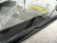
Back to our problem child of a window, this last crack occurred as I slightly pried rearward with a metal rule. Exactly where I pried.


IMG_3161.jpg


To limit the excess squeezed out of the seals, we took the 3M strip-calk in its original form and sliced right down the middle..


IMG_3202.jpg


IMG_3203.jpg


Here's a video showing installation of the strip-calk, and another with installation of the seal over the strip-calk.


Installing this one, we had a slight tight area and I asked Jared to push outward and that's when we had a repeat of Groundhog Day..


IMG_3220.jpg


So, maybe the pry the first time was not the only issue. Fast forward so we can look back, last night we did a dry fit of the garnish moldings around these windows and found that the tack strips holding the headliner were far too thick and pushed the moldings down so far the back side would be visible through the glass. So in addition this was also pushing downward on the window and seal while we were attempting the installation. When we had installed the quarter panel previously, we used plug welds inside this window opening and some had a slight proud. Nothing that I was concerned with at the time and considering had the tack strip been the correct thickness it likely wouldn't have been an issue now. But with the headliner pushing downward, the seal was hanging up on one of the plug welds as Jared was pushing outward on the corner, which made a perfect fulcrum effect for crack #2. Since we aren't pulling a headliner out, we went ahead an cleaned up the plug welds. This meant taping off all the nice pretty paint on the outside and the interior as well..


IMG_3254.jpg


IMG_3255.jpg


All of the welds cleaned up, we mixed up some SPI epoxy and used a small brush to add three coats on the bare areas. And to counter the effect of the garnish molding hanging too low, we will now need to make some one-off upper clips that are half height of the ones we just ordered (and have been waiting 4 months to arrive), in order to get the molding up and out of sight when looking through the glass. Story of my life..


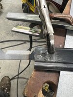
Window #3!! We had length issues from the last replacement, let's check this one as well. Hooking our tape measure on the apex of the pointy end, the original ordered with the rest of the glass set shows to be 40-1/16 in length. The new replacement, like the last one (#2), was 40-5/16. So we have a 1/4" to remove.


IMG_3277.jpg


IMG_3278.jpg


IMG_3282.jpg


IMG_3283.jpg


IMG_3280.jpg


IMG_3281.jpg


So we consulted my glass expert John Glenn the last time we did this, and got the run down of the various methods we could possibly use. Since I'm more of a go slow and sneak up on the end goal, I opted for abrasives, we'd use Cubitron belts on our Dynabride sander. It did a better job of taking down corners as opposed to the entire flat area, so we followed the process discussed in the next video. Then when we had reached the size needed (three hours later), a 320 grit disc on the DA gave a more polished appearance. Safety disclaimer: eye protection and N95 respirators, although not mentioned in the video, were used and are highly recommended !!!


IMG_3306.jpg


IMG_3307.jpg


Our installation last night went in relatively painless and crack free. Now to make some upper clips..


Last edited:

BORING HOP YARD

Well-known member
Joined
Jan 13, 2007
Messages
1,098
Location
Boring Oregon
First, I want to thank Robert for sharing some of the challenges, causes and solutions they encounter. I do have to admit I was a little surprised the side windows were not tempered. I would have assumed the windshield would be the only laminated glass. I have never worked on tri-five glass before. Again, thank you for sharing!
 

white6589

Well-known member
Joined
Feb 27, 2011
Messages
351
Location
Maryland
I agree xtremek.

His explanations gave me a lot of confidence in tackling my current resto project.

Robert should publish it in book form.
 
To avoid these ads, REGISTER NOW!

RickP

Well-known member
Joined
Jan 15, 2013
Messages
1,547
Location
Annapolis, MD
+1 ^^^

After, a seamless video wall just shy of 24' long... much better suited to this classroom setting..


IMG_2538.jpg
Not a bad gig for your day job!

I really like how you were able to combine your "work" and "hobby" skills there. That panel mount looks better than factory made.

Funny story, one of the tech reps that showed up from Cyviz swore this wall mount was their product... :ROFLMAO:

"no, one of my guys made it in his garage" He didn't believe it...
Classic!

Absolutely beautiful work on the wagon -- I'm amazed at how much work goes into getting all the details right.
 

Monza Harry

Well-known member
Joined
Dec 29, 2018
Messages
1,433
Location
Windsor ON
Thanks for the comments guys.. Yeah, may as well share the good and the bad. Cheaper to learn from others mistakes, but only if you hear about them.
Bob that deserves a "You're the Man" for owning the Boo Boo and a "Thank You" for sharing that and everything else here!
Be thankful that was a Tri-Five Chevy, for my Monza, the windshields are only produced when the have enough requests, what are "Enough Requests?" Nobody seems to know, somewhere around 5 to 10 years! Yes seriously and side glass I'm still looking for 2 rear quarter glasses for over 7 years I haven't been as diligent the last ~3ish though [I have two but they aren't the ones I asked for and returning them was as much as I paid for the glass]. Harry
 
OP
M

MP&C

Well-known member
Joined
Oct 21, 2009
Messages
4,396
Location
Leonardtown, MD
Thanks for the kind words everyone. Now for a slight distraction in the shop... A good friend of mine has a powder coat business and has been restoring a Kent model KMX850 bmx bike. The bike was found in the woods and was brought to him for repairs, with many of the obsolete parts being sourced from other style bikes and scooters. Here is where he has it thus far..


IMG_3343(1).jpg


Once the sun had taken its toll on the seat upholstery, the foam inside became a nice sponge for all the precipitation that Mother Nature could throw at it, leaving much of the seat pan gone. So he needed a seat pan fabricated, and this is where I entered the picture..


IMG_3344(1).jpg


His major concern was that we duplicate the impaling spikes to secure the upholstery.


IMG_3346(1).jpg


I had attended an estate sale about a year ago and picked up a set of Malco notchers, not knowing what I'd ever need them for, but also knowing I couldn't do without them.


IMG_3398.jpg


IMG_3397.jpg


IMG_3396.jpg


So when I pulled these out of the tool box all fears had been abated..


We started with a piece of 19 gauge AKDQ and used Stan Fulton beading dies to add the center bead.


IMG_3350.jpg


IMG_3358.jpg


A piece of 5/8 round stock on the magnetic brake then added the radius for the side bends. Some of the 5/8 round stock was also used to make some post dollies with a welded stop for use in the bench vise..


IMG_3372.jpg


Basic shape


IMG_3368.jpg


The Erco kick stretcher used on the sides and the post dollies on manipulating the radius bend helped to provide the kickup needed at the rear.


IMG_3369.jpg


A solid rod across the rear mounting holes gives us some critical dimensions for layout....


IMG_3386.jpg


IMG_3387.jpg


IMG_3388.jpg


For the mounting holes in the rear, we measured 9/16 from the edge to hole center as per original, and then made a two ended transfer punch that fit snugly between the sides. Once we had our rear measurement and the point aligned to the 9/16 scribe line, we tapped either side to mark the holes.


IMG_3389.jpg


IMG_3391.jpg


Once drilled, a rod through these holes lets us locate the front bracket. We reused the bracket to save some time (and money) as it was still good and solid..


IMG_3403.jpg


Impaling spikes added


IMG_3404.jpg


IMG_3405.jpg


All bracket installed and assembly gets media blasted to prep for powder coat.


IMG_3408.jpg


IMG_3409.jpg
 
Last edited:
OP
M

MP&C

Well-known member
Joined
Oct 21, 2009
Messages
4,396
Location
Leonardtown, MD
I did use the Malco notchers, the beak does go through first to help start the cut. I had actually cut a couple pieces of aluminum tubing that were a snug fit over the handles to make the initial punch a bit easier. This was more a controlling factor so I didn’t have to squeeze so hard and wind up cutting all the way through. The additional leverage allowed moderation, so to speak.
 

Modern Garage

Well-known member
Joined
Mar 26, 2015
Messages
583
Location
Southern Minnesota
I think I follow. It's a question of scale: the seat pan is smaller than the car stuff we're used to so the Malco reached in to the right depth and the length of the tubing handle extensions allowed just a "punch" and not a complete notch, then I'm guessing you finished off by bending the punched tongue up straight. Right?
 
OP
M

MP&C

Well-known member
Joined
Oct 21, 2009
Messages
4,396
Location
Leonardtown, MD
I punched the entire perimeter and then went back and push the spikes straight in using a small screwdriver. Started in a corner and worked around, I lucked out without a scratch. Still have the upholstery guy to go yet.

Thanks for all the kind words guys!
 
Last edited:

klhansen

Member
Joined
Jan 28, 2021
Messages
8
Location
Eagle River, Alaska
Robert
You're a man of many talents: cars, trucks, bikes, video screens, whatever. I always see something amazing when I look at your work. :thumbup: It's just too bad that glass is so fragile. I'm dreading the day I get to glass install on my project. :eek:

I posted a PM for you over on Stovebolt if you have a few minutes. It's right down your alley.

Thanks
Kevin
 
OP
M

MP&C

Well-known member
Joined
Oct 21, 2009
Messages
4,396
Location
Leonardtown, MD
Something I forgot to post, We had made a road trip to Virginia a couple weeks back and picked up a Vintage Cengar planishing hammer, in it's factory box with dies..


IMG_3227.jpg


IMG_3228.jpg


IMG_3229.jpg


IMG_3230.jpg


IMG_3236.jpg


IMG_3237.jpg


This, along with a Chicago Pneumatic pedestal planishing hammer. This had been modified at some point in it's life to add more throat depth for planishing larger panels.


IMG_3231.jpg


IMG_3232.jpg


IMG_3233.jpg


IMG_3234.jpg


IMG_3235.jpg
 
To avoid these ads, REGISTER NOW!
Top Bottom