To avoid these ads, REGISTER NOW!

MP&C Shop Projects

OP
M

MP&C

Well-known member
Joined
Oct 21, 2009
Messages
4,396
Location
Leonardtown, MD
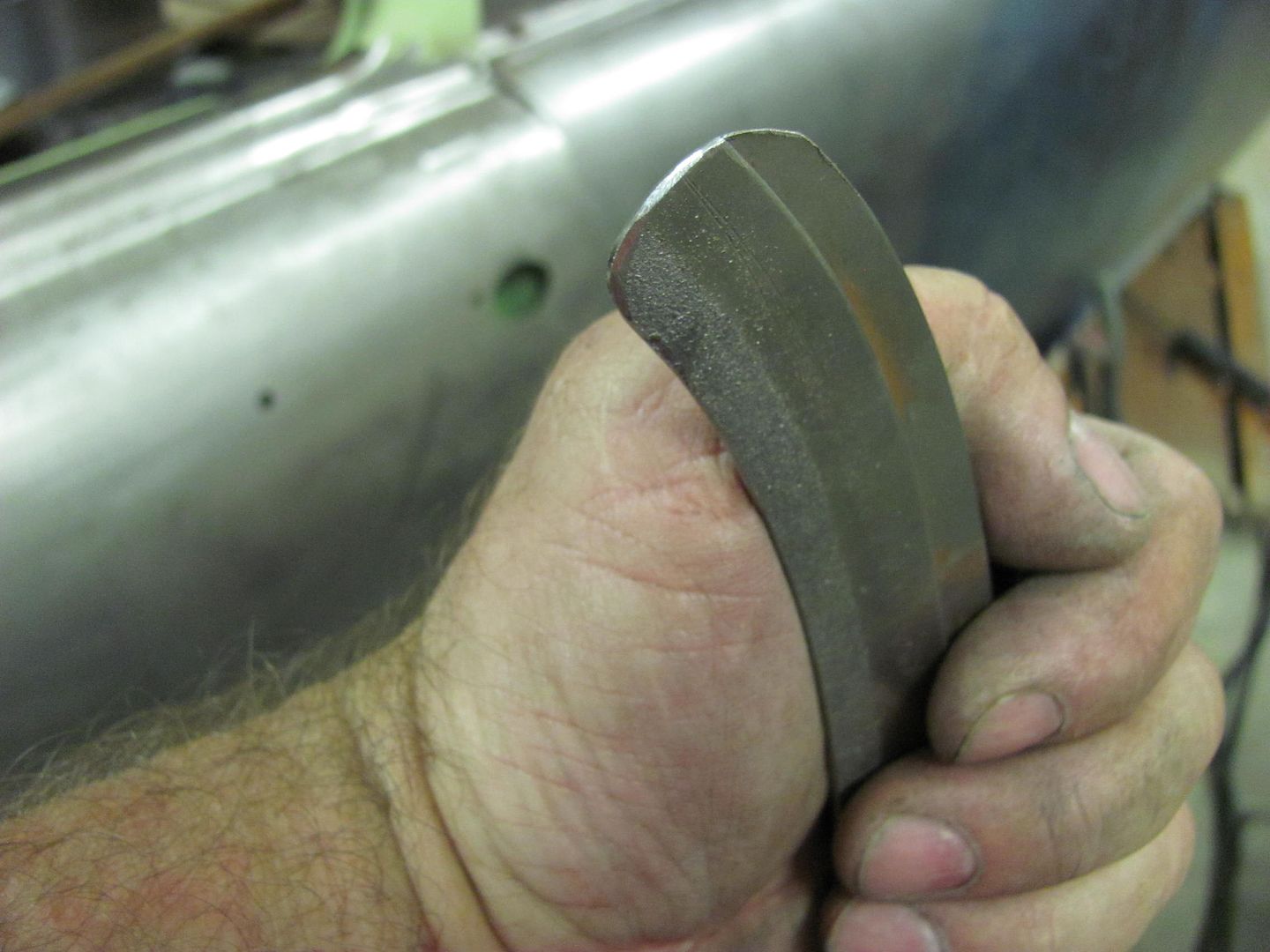
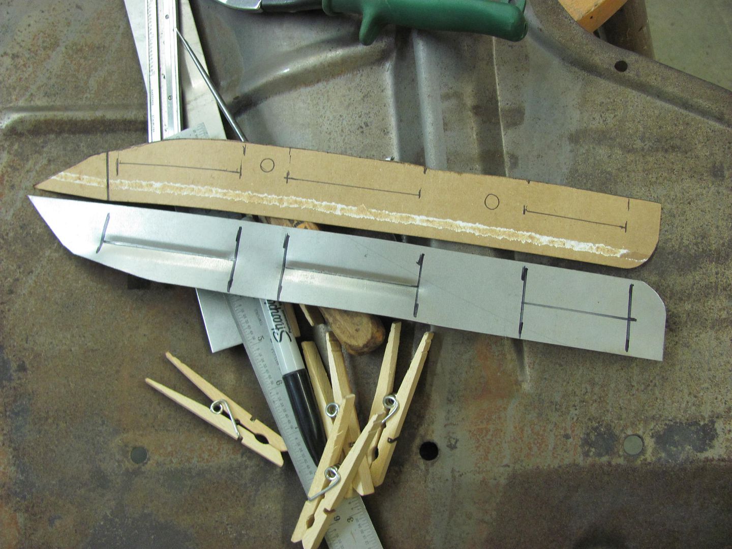
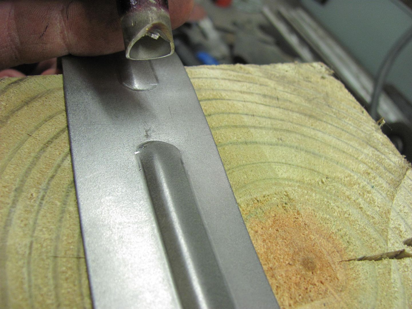
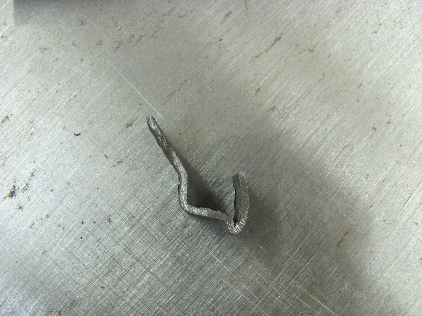
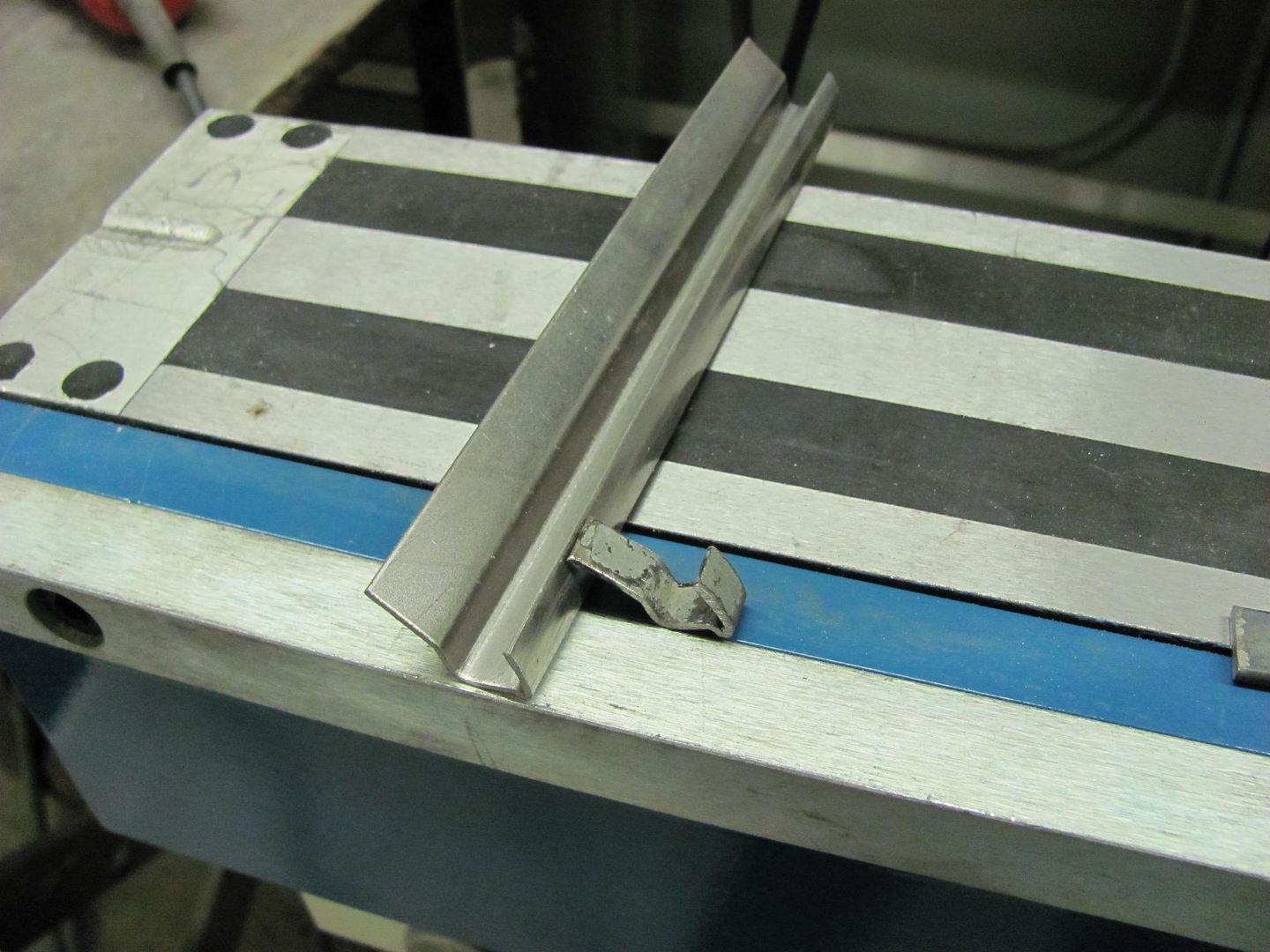
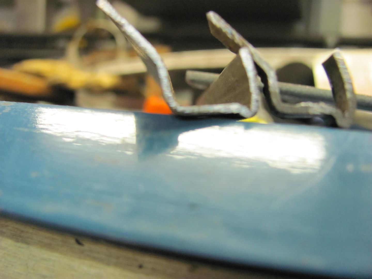
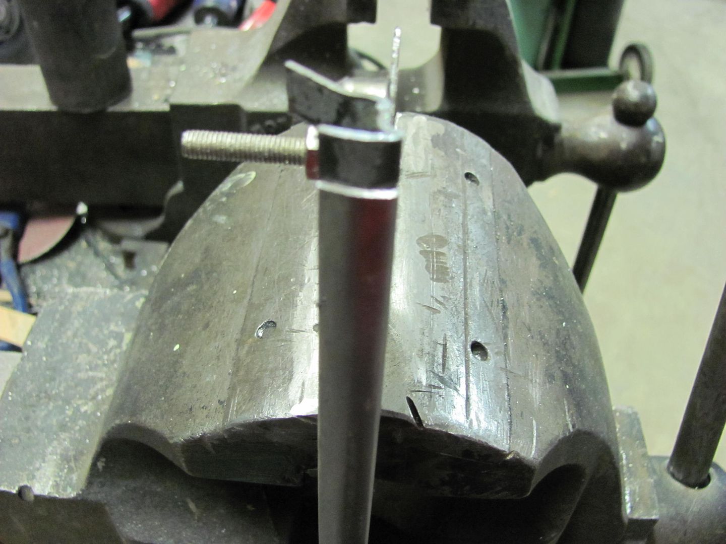
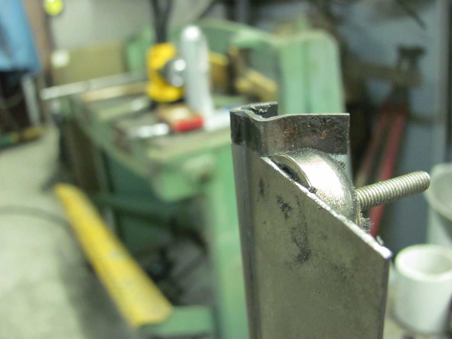
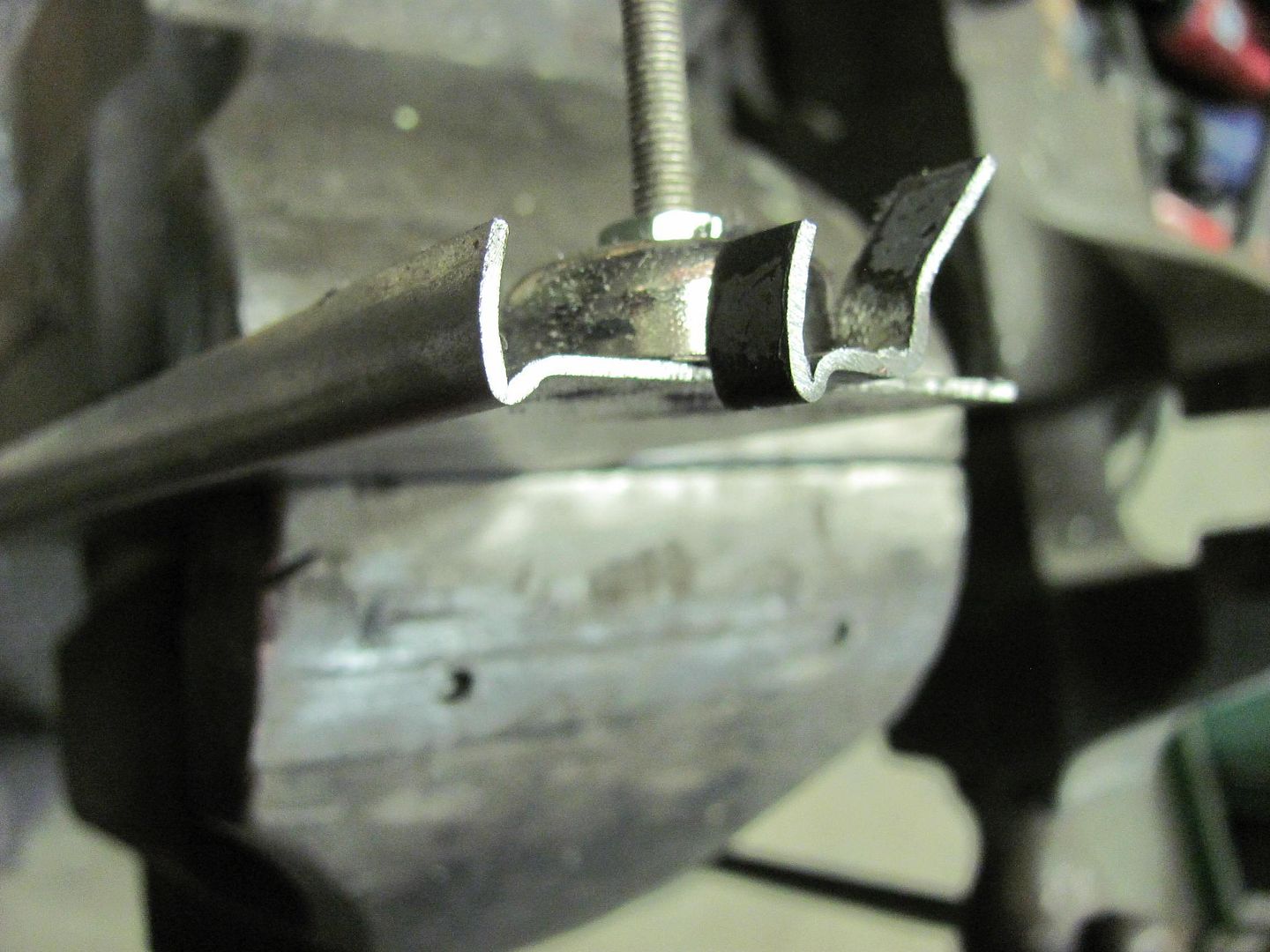
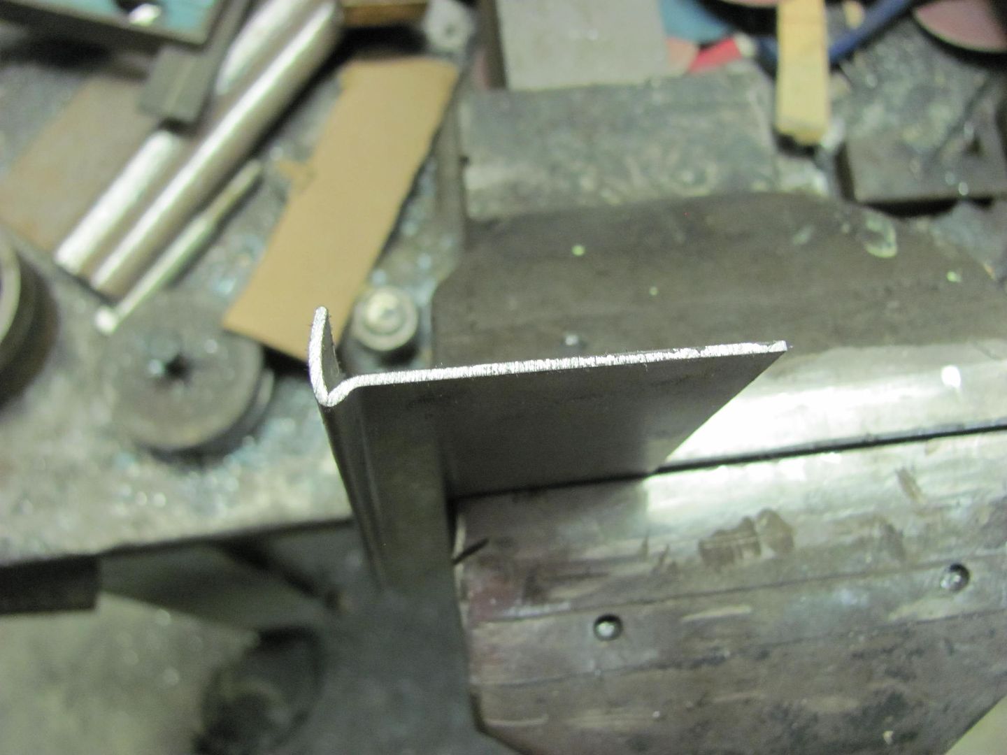
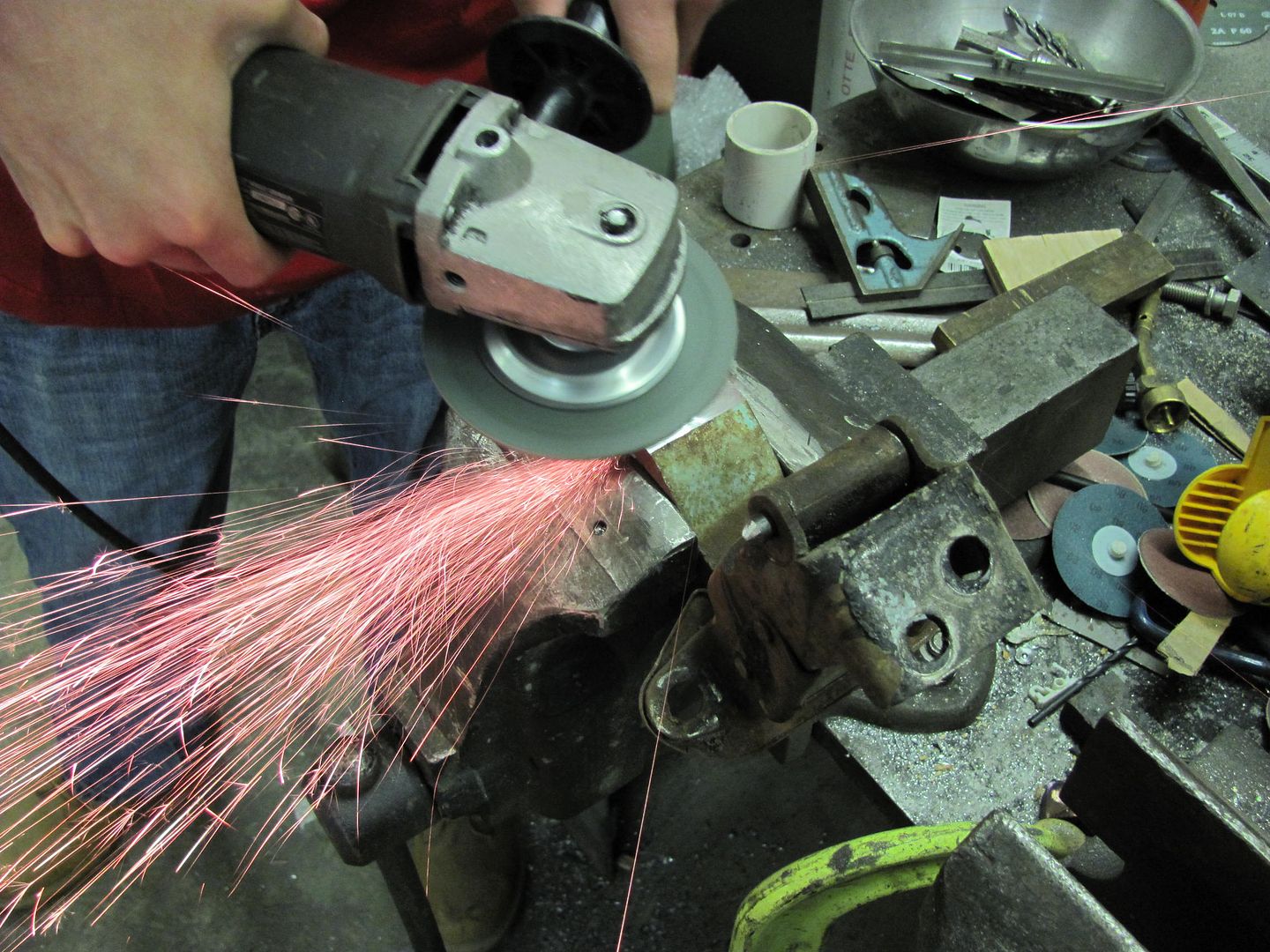
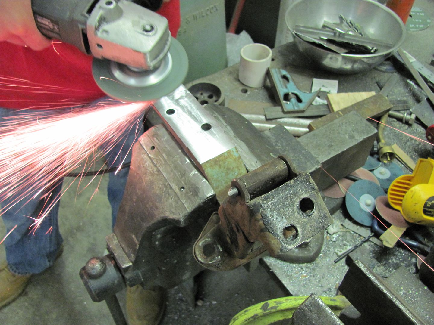
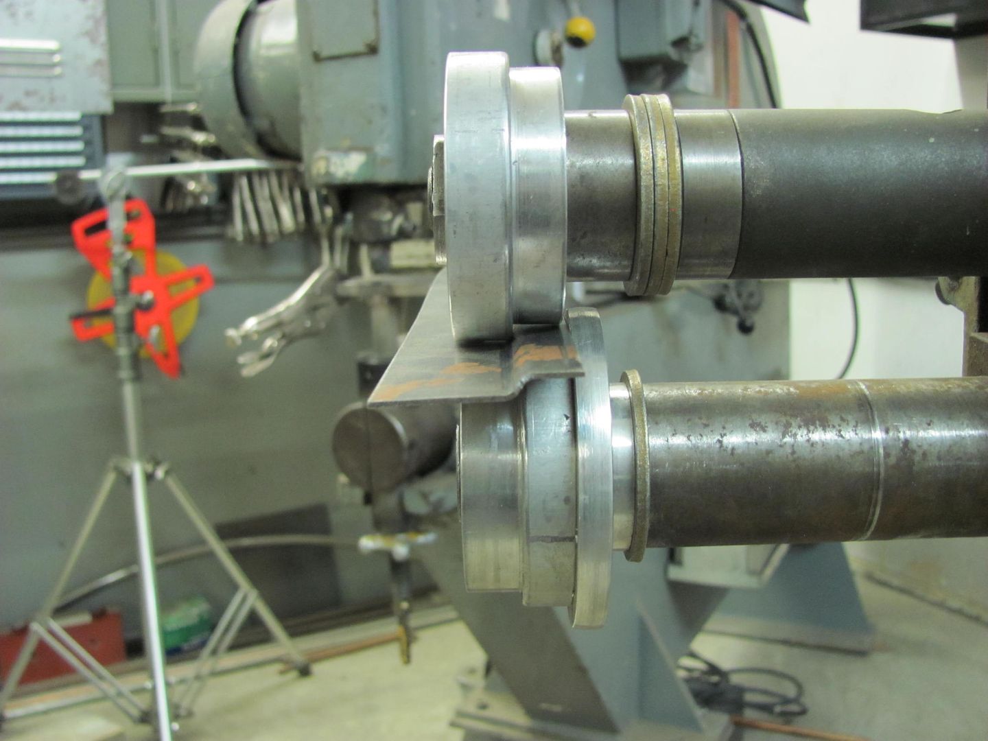
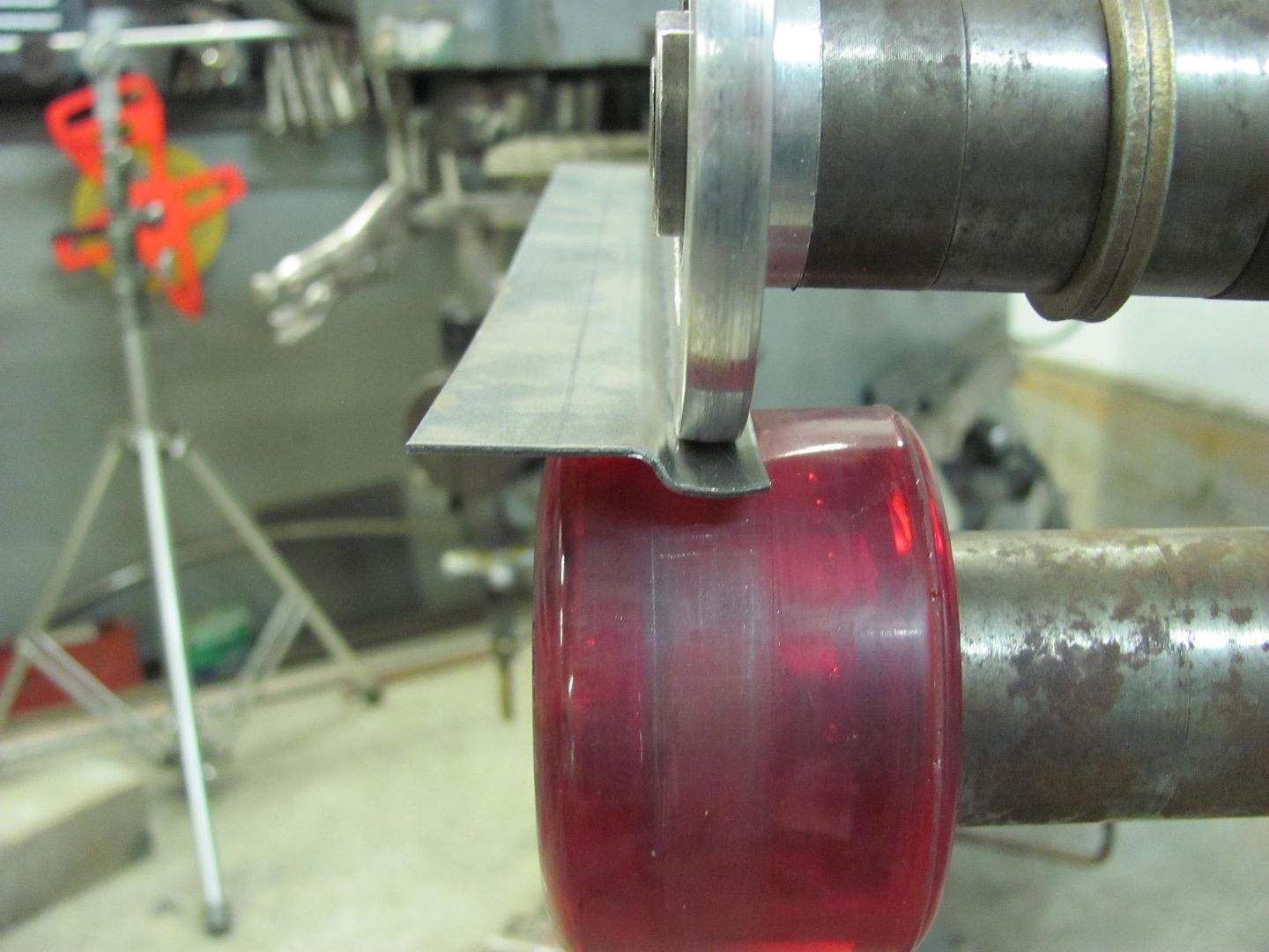
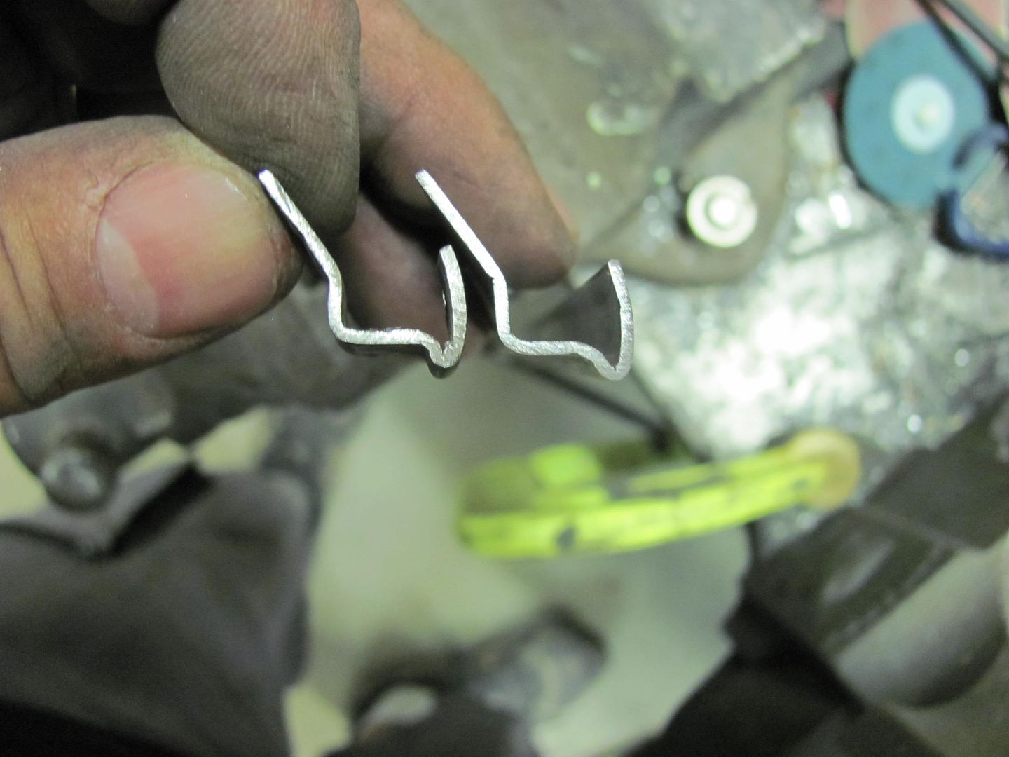
Ed, the lower plate was CRS and the slot was milled on a Bridgeport J head. The punch was made from a piece of round stock, milled to the correct width and touched up with a file. Highly technical stuff here.. :lol: No heat treating unless you want to count the welding process.


Claude, I think he's going to work out well. 16 year old son of a guy I went to school with, lives about 2 miles away, so convenient for him. I did let him know he had to keep grades up as I didn't want to catch the wrath from his mother.. :willy_nil
 
To avoid these ads, REGISTER NOW!
OP
M

MP&C

Well-known member
Joined
Oct 21, 2009
Messages
4,396
Location
Leonardtown, MD
Just a test today to see if I could bend up some Jeep Cherokee drip rail to match the small sample I was sent in the mail. This was done with 18ga crs using the bead roller, mag brake, and press brake. The layout details needs just a bit of tweaking, but I think it may just work...


Picture430.jpg


Picture433.jpg


Picture434.jpg


Picture436.jpg


Just as a follow up to this drip rail, the dies I used in the original attempt had about a .07 offset. I didn't want to alter their size as they get used once in a blue moon for sheet metal offset, like I did for the 55 Chevy truck windshield panel.. So I decided to make another set, and based on the dimensional difference between the good sample and the trial piece, it looked like I needed to add about .04 to the offset, or .110 total. So here are the new dies...


Picture1088.jpg


Picture1089.jpg


I again used the "backstop" die, and had to go back and trim a bit more off the width of the lower die to get the drip rail height correct.


Picture1076.jpg


Picture1077.jpg


Picture1078.jpg


Then the "backstop" die was radiused to use with the skateboard wheel in providing the radius for the front face...


Picture1079.jpg


Picture1080.jpg


Then a few passes with the tipping die to fold up the front face...


Picture1081.jpg


Picture1082.jpg


The ends wanted to fold much more than the rest of the trial piece, so rather than continually readjust the tension, I sacrificed the first inch or so and just cut it off in the band saw.


Here is the outer portion formed, the height is about perfect, this is using die width and back stop to regulate dimension...


Picture1083.jpg


The offset also turned out much better. The sharp bend on mine wasn't quite as tight together, but we'll see what the Jeep guys say to this version.....


Picture1084.jpg


Picture1086.jpg


Picture1087.jpg
 
Last edited:

mhinch

Member
Joined
Feb 16, 2008
Messages
24
Robert,
I'm in the tear down stage of rebuilding my 1983 scrambler. I need to fabricate repair sections for the rear wheel arches. It appears to be a very basic profile. what's not basic about a jeep, right? I've thought about both using a bead roller or making forms and hammer forming the pieces. Below are a few pictures for reference. I've gauged the sheetmetal and it's 18 ga. I do have access to a lathe to turn down some special dies if need be.
Thanks for your reply and all of your help.
First try at tapatalk so I hope it works!

zezyvepa.jpg

3aruzery.jpg

5yzerydy.jpg

esepuvy4.jpg
 
Last edited:
OP
M

MP&C

Well-known member
Joined
Oct 21, 2009
Messages
4,396
Location
Leonardtown, MD
Matt, do you have a picture that shows the "rust" any better? Like a view from farther back to see more of the fender?

Just from the close ups there it appears to be just some surface rust and slight pitting around the mounting holes for the fender flare. If that's the extent of the issue, you may find that media blasting the pits, epoxy primer, and glazing putty will fix what you have. I do notice that you have double wall construction, so the likelihood of some internal rust issues is also a possibility.


If this repair does warrant fabrication, this is something that could be done on a bead roller, and could also be done on a reciprocating machine like my Lennox. The trouble spot here is that any welding done on the outside may affect any finish on the inside panel. Are these two panel able to be separated in any way, ie: is this a bolt together or is everything spot welded?
 

aggierailroad

Well-known member
Joined
Jan 8, 2012
Messages
581
Location
Houston, TX
Every time I see all that you can do with a bead roller, I get more and more interested in making some tweaks to mine and getting some new rollers.... Very versatile tool.
 

mhinch

Member
Joined
Feb 16, 2008
Messages
24
They're here now......on to the pictures Robert.
The passenger side does have some picking but there is no rust through. To your point all that is warranted there is a blasting and epoxy primer then fill and sand.
The pass side

unesunyp.jpg


Another pass side

nydu3u7a.jpg


Here's the bad drivers side

ba4ytemu.jpg


gubudene.jpg


e9y9ame7.jpg


6ujuqabu.jpg


It's just a single layer of 18ga, no double wall. I can just grind inside smooth since I plan on re-coating inside of tub with color matched liner.
You're a great help and thanks for taking the time.
Please describe the technique and tools you would use to accomplish this repair
 

mhinch

Member
Joined
Feb 16, 2008
Messages
24
I've removed the liner on the inside and have started on the underside. What a mess. This is true ding a ling work!

vy5egujy.jpg


upuga7e8.jpg


Good news is that I took the tub off in about 2 hours!

ezymytat.jpg


Engine may come out tonight
uby8u3ur.jpg


Thx for looking
 
OP
M

MP&C

Well-known member
Joined
Oct 21, 2009
Messages
4,396
Location
Leonardtown, MD
Matt, what I'm going to suggest is to use a hammer form. Start by looking here at this link from post 65 and on, I'm working on a 55 wagon tailgate. Towards the bottom of the page I start using MDF to make a hammer form and show some of the process.

http://www.garagejournal.com/forum/showthread.php?t=81325&page=4


Now, looking at this picture, cut out a piece of MDF sheet (about 1/2 or 3/4 thick) in the shape shown, but a little wider for more strength (all the room I had on the picture :lol:). Then cut another to match the shape of the wheel opening detail out of 3/8 mdf (given it's thickness), router the edges and screw to the larger sheet. Align/trim edges at the opening as needed. Cut a piece of 19 or 18 ga cold rolled steel in the shape of the 3/8 thick part, allowing about 1" for the flange at the opening, and a good 2" for the top part to transition into the side of the quarter panel. Make another "clamping" piece of MDF out of the thicker and place on top of the sheet. This should be slightly smaller in width to allow plenty of room for hammering/corking around the radius. Clamp using c-clamps, and you can even run some screws through the whole works to help keep things from moving. Will just have to weld them closed later. That's the down and dirty version of making this on the cheap, if you had a Pullmax machine you could make it with that. I'd say the bead roller would be challenged to put that much offset in without notable distortion in the panel. BTW, in order to use the c-clamps at that edge, you'll likely be repositioning many times to keep them at the edge of a table/workbench to give a good stable surface for hammering, unless you want to run screws completely through and into the workbench, then just use the clamps where they will reach.


attachment.php
 

Attachments

  • Matt Jeep tub.jpg
    Matt Jeep tub.jpg
    115.8 KB · Views: 1,560

Skyline

Well-known member
Joined
Nov 11, 2008
Messages
3,586
I know you have some mad skills, but isn't already-formed sheet metal available for that fender lip? It's not exactly a rare vehicle.

Or better yet, some pre-made flares? There are some where you cut the whole lip away to clearance for larger tires. There are some that are flexible plastic, (ie Bushwacker) and others that are more rugged....usually built to combine with armored rear corners.
 
OP
M

MP&C

Well-known member
Joined
Oct 21, 2009
Messages
4,396
Location
Leonardtown, MD
I'm with you there, heck they even make a complete tub in F/G for no rust issues at all. But I was just going by this.....

Robert,
I need to fabricate repair sections for the rear wheel arches.


Just passing on how I would do it (with minimal tooling)..
 
OP
M

MP&C

Well-known member
Joined
Oct 21, 2009
Messages
4,396
Location
Leonardtown, MD
The shop's new apprentice started last night, so we did some more metal bumping on the roof repair. We had some high spots to address, so Kyle held the shot bag on the inside while I used the body hammer on the outside.
Picture1090.jpg


I used the blunted pick end of this hammer to address the narrow high spots. I've found it helps to more precisely locate your "strike area" by laying a guide finger next to it. Tap down the area, move to the next....

Picture1091.jpg


We did have a larger high spot that made use of the hammer face, and on the bottom side Kyle held the donut dolly in place. This made short work of bringing down the high spots..

Picture1093.jpg


Note the "graduated" markings on the roof are also on the inside to keep inside guy and outside guy on the same page with hammer and dolly alignment.
 
OP
M

MP&C

Well-known member
Joined
Oct 21, 2009
Messages
4,396
Location
Leonardtown, MD
Thanks!

Today we worked on tying up some loose ends. We had a slight mis-alignment at the front corner of the passenger door..


Picture1094.jpg


The lower hinge had already been adjusted as far as the floating nut would let it...


Picture1095.jpg


So the door was removed, and since we have no milling machine, we went through about 8 of these 60 grit sanding discs..


Picture1096.jpg


Picture1097.jpg


Picture1098.jpg


Picture1099.jpg


For a better comparison, here's the before again...


Picture1094.jpg


After


Picture1100.jpg
 
Last edited:

Kevin54

MEMBER EMERITUS
Joined
Jan 12, 2005
Messages
29,341
Location
Urbana, Ohio
Picture1100.jpg


Robert.....just curious, but is the rocker panel going to be addressed also?

And when you are bending up your drip edges, are you doing that mostly on your new magnetic brake? If you are, can you show us on the other end of the computer lines how you are doing it. I think I've been following everything along in this thread, but maybe I missed it. I'm guessing the brake is working out as expected, or maybe better than expected?
 
To avoid these ads, REGISTER NOW!
OP
M

MP&C

Well-known member
Joined
Oct 21, 2009
Messages
4,396
Location
Leonardtown, MD
Yes, we were discussing that yesterday while going over the remaining tasks. That's another reproduction part that leaves a lot to be desired. It doesn't have quite enough concave to it's radius. I have a plan for that as well, we'll see if it works.

On the drip rail, both of those last practice pieces were done strictly on the bead roller. I am going to try another version partially using the mag brake in hopes of better consistency.


Thanks for the comments and questions!
 
OP
M

MP&C

Well-known member
Joined
Oct 21, 2009
Messages
4,396
Location
Leonardtown, MD
Kevin, I did another sample of drip rail to try and tighten up the bottom "vee". I did find that the mag brake will not do as tight a bend as the sharp tipping die. To be fair, I doubt an apron brake would either. It's either the tipping die or attempt some draw forming.


Sample flanged as before...

Picture1103.jpg


....and radius added to the front face...

Picture1104.jpg


Before I had used the tipping die at the crease adjacent to the radius flange only, and in an attempt to keep the vee tighter, I also flipped the piece over and used the sharp tipping wheel on the back side. Once the flange was tipped, I also used the tipping wheel (with backstop) to mark the other two folds.. Then the obtuse angle was folded using the tipping wheel, the 90 was folded using a gooseneck die in the press brake. The vee is a bit tighter than before, I think I'll see if I can borrow the stainless cover from Jonathan's cut roof section to see how well that part fits...

Picture1106.jpg
 
OP
M

MP&C

Well-known member
Joined
Oct 21, 2009
Messages
4,396
Location
Leonardtown, MD
Robert.....just curious, but is the rocker panel going to be addressed also?


Here you go Kevin!

With the lower corner of the door fitting better, it becomes all the more obvious how poor of a reproduction these outer rocker panels are. The "concave" radius does not match the fender to the front or the quarter to the rear of the rocker. This would have been a good fix using the Wheeling machine with a Go Kart slick, had it been noticed before installation.

Picture1100.jpg


Add some body flex to the mix, and trying to fix this with filler would likely be a short lived repair.


Matching the lower anvils of the Wheeling machine to the radius on the quarter, this one fits the best. Also notice how it doesn't fit as well in the rocker panel..

Picture1108.jpg


Picture1107.jpg


At this point I thought I'd try a "portable" version of the Wheeling machine to add a bit more radius to the rocker panel.

Picture1109.jpg


Picture1110.jpg


Built in guide......

Picture1112.jpg


After some "wheeling", and some bumping of the leading edge with a door skin hammer:

Just to show the comparison, before
Picture1100.jpg

After:

Picture1113.jpg


Picture1115.jpg


Picture1116.jpg


Picture1117.jpg
 
Last edited:

csp

Well-known member
Joined
Mar 23, 2010
Messages
5,719
Location
Franktown, CO
How much time was spent rolling that? Even pressure the whole time or does it vary as you see it begin to take shape?
 
OP
M

MP&C

Well-known member
Joined
Oct 21, 2009
Messages
4,396
Location
Leonardtown, MD
I started on a creeper and found the casters counter-productive. :tard:

Once I put the piece of diamond plate on the floor I could get a bit more pressure applied. Rolled it back and forth a few times with pressure applied, and even though it has a guide, by adjusting height of handle end, you could move anvil's path up and down on the rocker about 1/2 to 3/4 inch. So worked it front to back and then moved postion slightly and repeat. Pretty much even pressure the whole time... About ten minutes it was done.
 

Kevin54

MEMBER EMERITUS
Joined
Jan 12, 2005
Messages
29,341
Location
Urbana, Ohio
Picture1110.jpg


Picture1113.jpg


Well if that just ain't the **** right there. when you said you had an idea, I figured you had a long round piece of tubing or bar that you would lay in there and bump and thump until you got the rocker worked back. That roller is super slick. See, if your helper was on top of things, he could have rolled you back and forth on the creeper. :lol:
 

that-guy

Well-known member
Joined
Sep 6, 2012
Messages
603
Location
NoVA
lovin the English wheel project. will be really eager to see it all painted up and put to use
 

nonhog

Well-known member
Joined
Nov 6, 2007
Messages
2,449
Location
Arizona (Tucson)
I started on a creeper and found the casters counter-productive. :tard:

Once I put the piece of diamond plate on the floor I could get a bit more pressure applied. Rolled it back and forth a few times with pressure applied, and even though it has a guide, by adjusting height of handle end, you could move anvil's path up and down on the rocker about 1/2 to 3/4 inch. So worked it front to back and then moved postion slightly and repeat. Pretty much even pressure the whole time... About ten minutes it was done.

WHAT!!!!! ......no video? :D
 

Galvonzo

Well-known member
Joined
Jun 27, 2012
Messages
136
Location
Modesto, CA
I started on a creeper and found the casters counter-productive. :tard:

Well, if anyone isn't too sure about that Newton guy and his third law, I'm sure this exercise will change their mind. What's also funny when you think about it, is that MP&C's metal banging is pretty much just Newton's third law put to work.
 
OP
M

MP&C

Well-known member
Joined
Oct 21, 2009
Messages
4,396
Location
Leonardtown, MD
That Newton fella would have field day over here.. :lol_hitti


More progress today, working on some metal bumping on the drivers quarter, so a profile template was needed... Took a 1-1/2 x48 piece of 19 ga and used the mag brake to fold it, then the bead roller to flatten.

Picture1123.jpg


Then used the kick shrinker to get it to match the contour of the rear of the door, this will give us a close match to the front half of the quarter...

Picture1125.jpg


Picture1126.jpg


If you shrink too much, no need to change dies, just shrink the rear portion of the template (away from the body)

Picture1124.jpg


Ends are radiused...

Picture1122.jpg


Then the factory battery tray (firewall mounted) was dissected to use with the "Factory AC car" parts, in order to mount the battery in the passenger front corner behind the core support.

Picture1129.jpg


...and all the parts were media blasted. We have some sheet metal plugs to punch out tomorrow for use on a couple of repairs of thin spots, and then the works will get mocked up on the inner fender for placement, weld the parts together, and off for powder coating.

Picture1130.jpg


One more tip for those doing mock-up/door fitment without latches, this will hold the door flush with the jamb. (Thanks to Laszlo Nobi for that idea)

Picture1127.jpg


Picture1128.jpg
 

E12-535iTurbo

Well-known member
Joined
Feb 27, 2014
Messages
492
Location
The Netherlands
I'm looking for a bead roller. There is one for sale local to me but the guys is asking 350 euro's including some dies. It's a nice Jörg one. Would it be worth it or is it overpriced?

I just don't have any experience with these. So all advice is gladly taken.
 
OP
M

MP&C

Well-known member
Joined
Oct 21, 2009
Messages
4,396
Location
Leonardtown, MD
Mine is a Fasti (Fastiwerks, Germany) and I paid $600 on craigslist for the machine, about a dozen or so die sets, a circle attachment, and workpiece support. A Jorg looks to be a very similar machine (I think they are called swaging machines in Europe?) and based on what I have seen with mine, I think the main limitation you will see is it has limited throat depth. For patch panels and formed parts like the drip rails I have been doing, they are fine. If you are doing bead work on full size sheet for floor pans, etc, that one may have limitation.


5302voet_3poot_vrij_1006041530441998_t3.jpg


350 Euro is presently about $450, but I would also check into the new pricing and IMO good used price would be anywhere from 25-40% of new. More than that and I would hope they had plenty of tooling. Gut feel is it sounds like a pretty good deal if it's the machine above and has a good selection of dies. If it's the electric machine for 450 Euros, better get over there yesterday.. :3gears:
 
OP
M

MP&C

Well-known member
Joined
Oct 21, 2009
Messages
4,396
Location
Leonardtown, MD
Tonight we turned our attention to inner fenders. We've got some items slated for powder coating, and these will get added to the pile.

Picture1131.jpg


The front edge that bolts outside the grille is showing remnants of water retention...

Picture1132.jpg


Picture1133.jpg


Mountain Dew template

Picture1134.jpg


Bead details to match the originals.....

Picture1135.jpg


Bead roller was set up with a backstop die...

Picture1136.jpg


Picture1137.jpg


Skateboard wheel and "rolling" wheel used to add radiused ends....

Picture1138.jpg


Picture1139.jpg


Picture1140.jpg


Grabbed a suitable scrap from the pile and used the sander to make a bead ender tool thingie, used on the treated 6x6 anvil...

Picture1142.jpg


Picture1143.jpg


Picture1144.jpg


Clamped and tacked....

Picture1145.jpg


Picture1146.jpg


More tomorrow......
 

nonhog

Well-known member
Joined
Nov 6, 2007
Messages
2,449
Location
Arizona (Tucson)
Nice! I have a similar repair ahead of me. Must practice a bit first.
See fender, where it meets inner fender? Notice the Fir needles on the one side. No wonder its rotted.
Thanks for the inspiration!
 

Attachments

  • shop%20020.jpg
    shop%20020.jpg
    66 KB · Views: 105
OP
M

MP&C

Well-known member
Joined
Oct 21, 2009
Messages
4,396
Location
Leonardtown, MD
That'll do it every time!


Well the Wheeling Machine finally has paint!

Napa Econo-etch primer....

IMG_20140911_160851906.jpg


H/K Pavo Purple and Flo Klear. I tried playing with the camera settings to get it to capture the true color, but it just wasn't happening. It may look blue in the pic, but it's about as close to Chrysler's Plum Crazy as you can get without putting a HEMI under the hood..

Picture1151.jpg


Picture1153.jpg


Picture1154.jpg


Here's the actual color...

BC10.jpg
 
To avoid these ads, REGISTER NOW!
Top Bottom