
You are using an out of date browser. It may not display this or other websites correctly.
You should upgrade or use an alternative browser.
You should upgrade or use an alternative browser.
MP&C Shop Projects
- Thread starter MP&C
- Start date
Thanks!
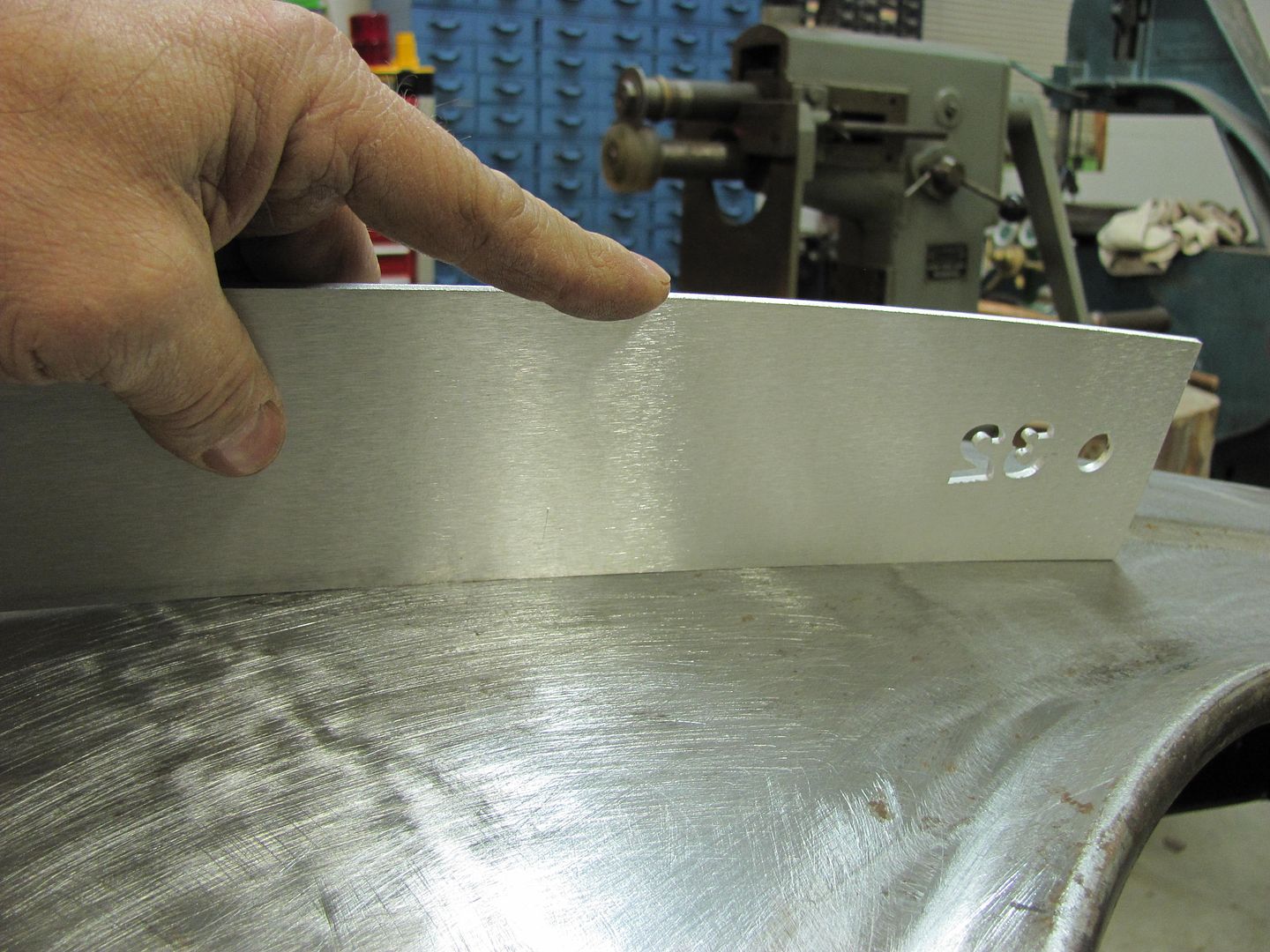
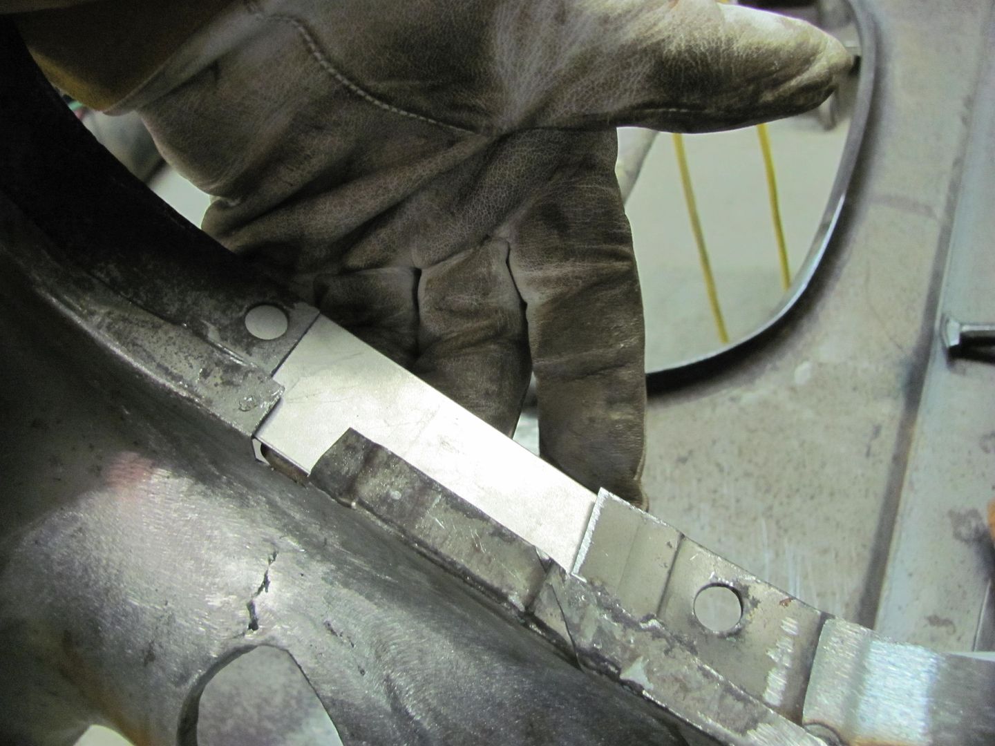
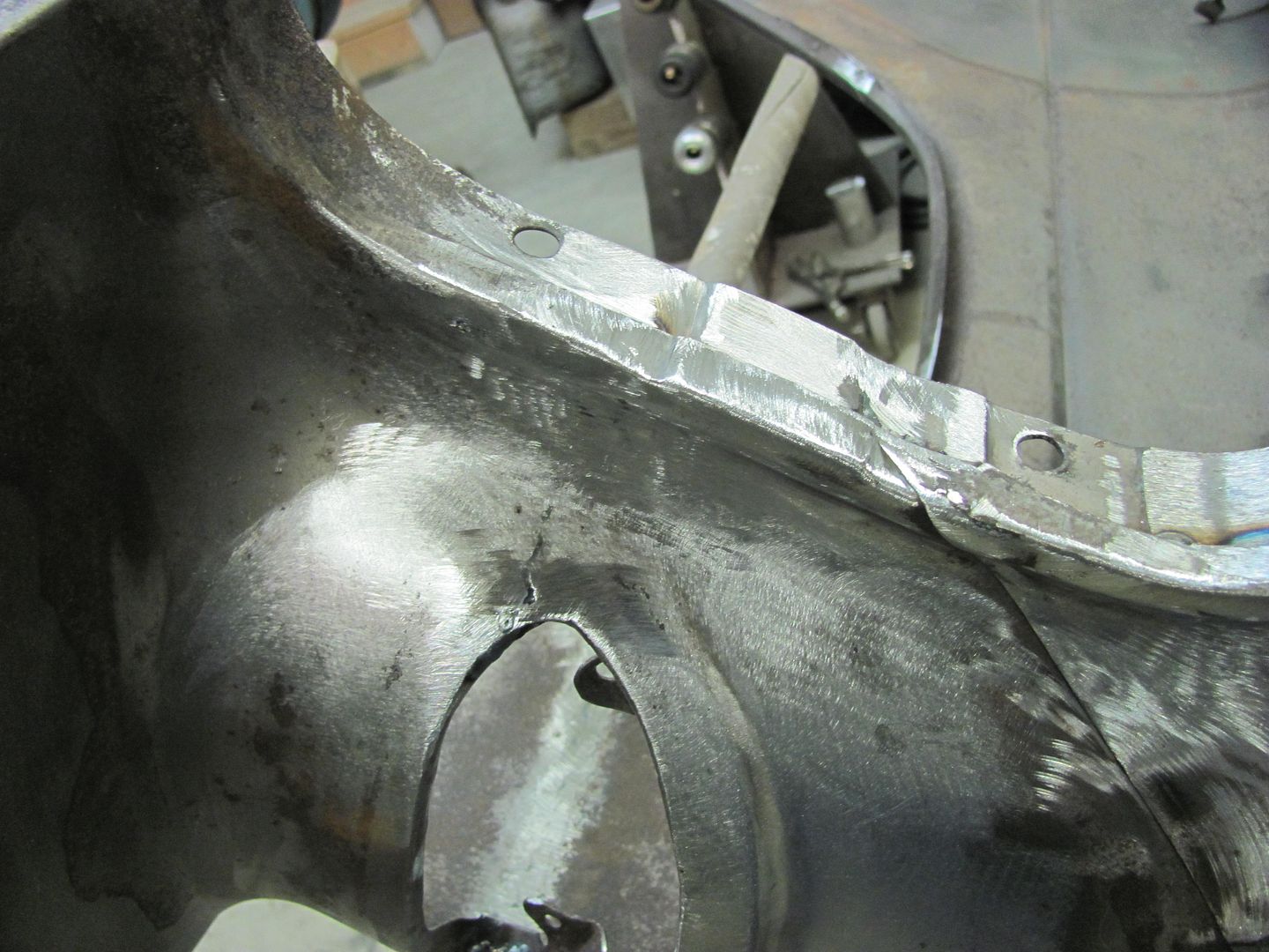
Continuing on the driver's fender, the top of the seam was trimmed....
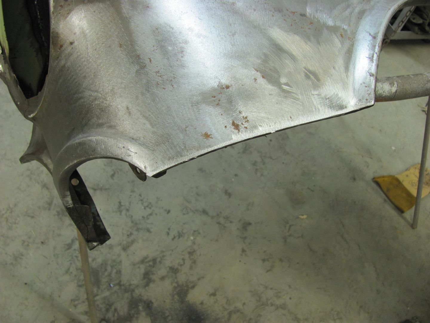
When trimming along through the center, I noticed a weak spot....


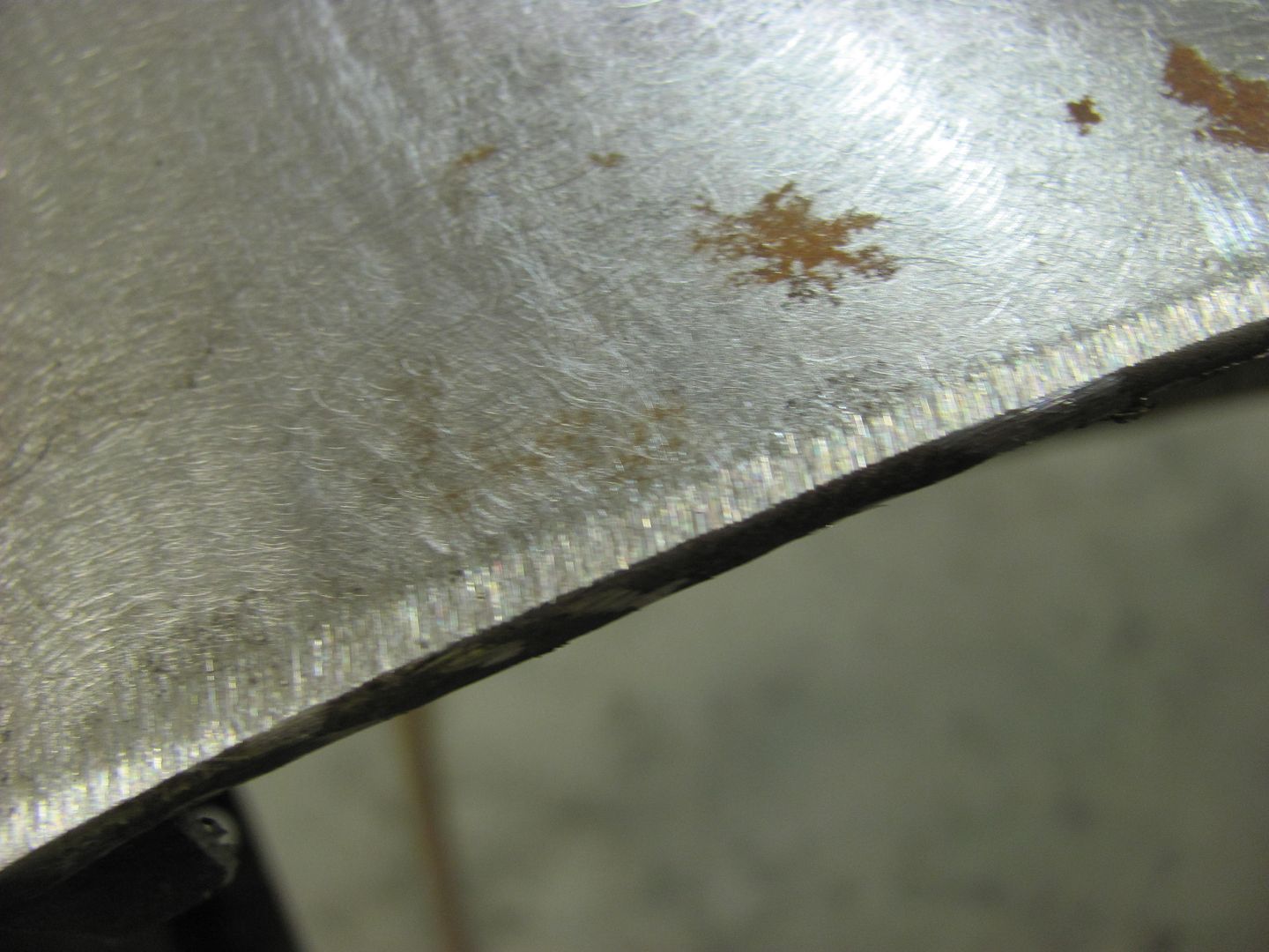
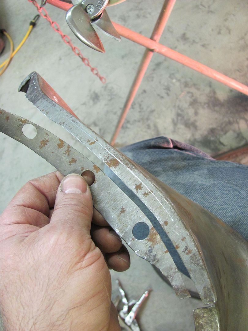
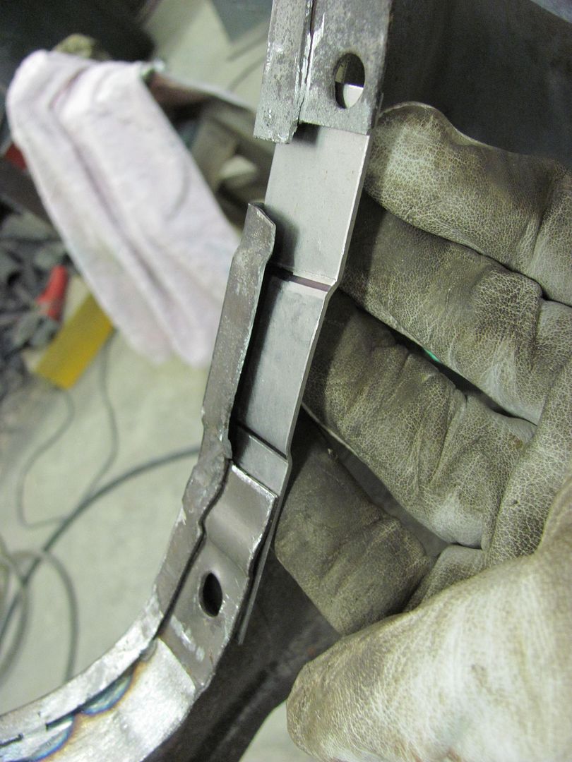
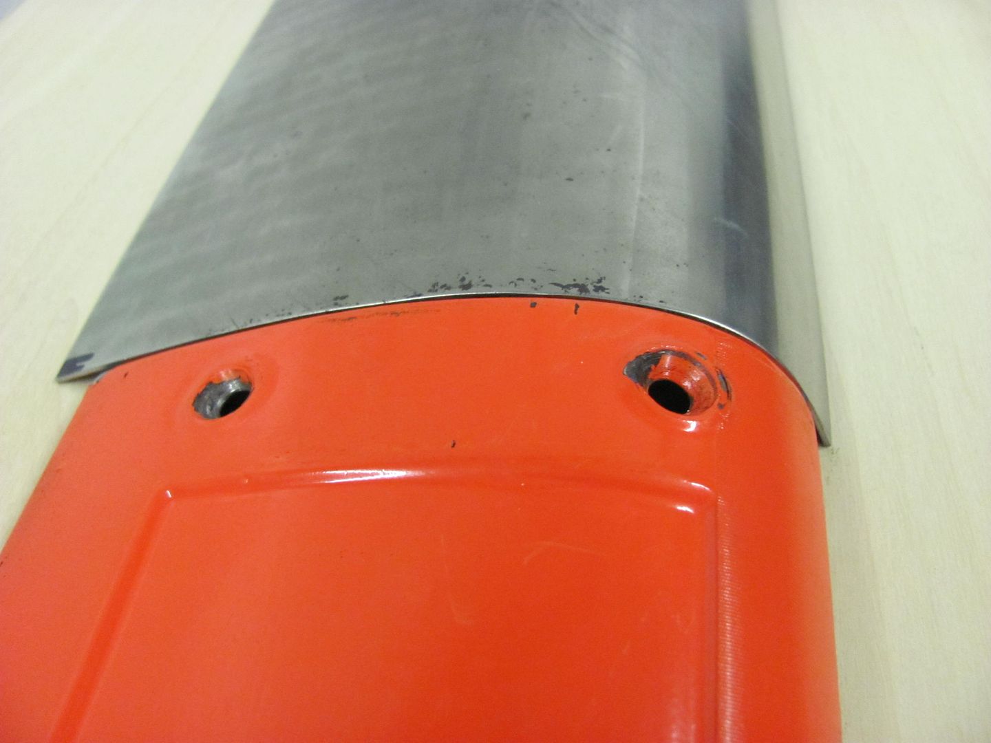
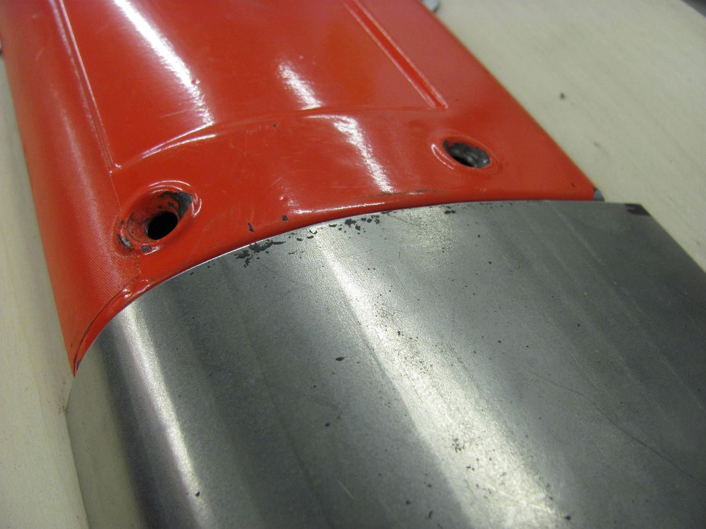
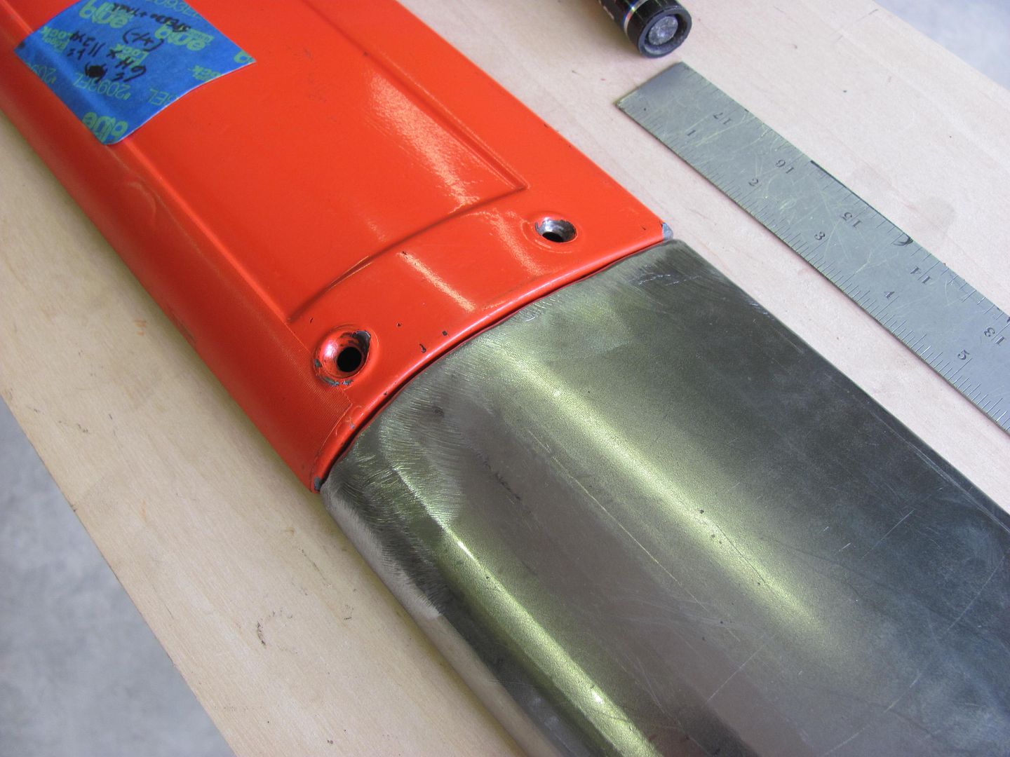
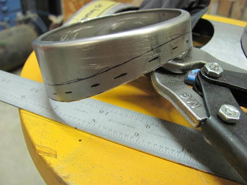
This is where some dirt had been trapped behind the bolting plate on top of the flange, and looks like it wouldn't have been long in coming through paint. To be able to trim the pitted area out, the lower section was trimmed with about 3/16 extra... see the scribe mark...
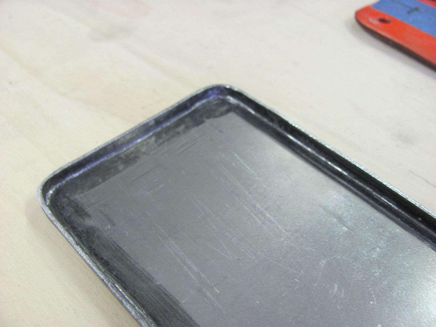
Planished flat..

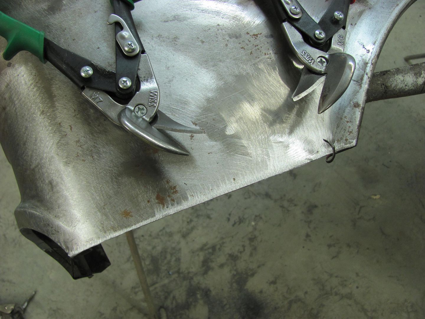
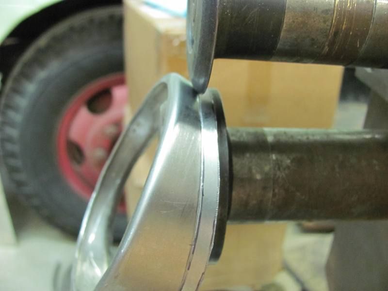
Clamped over fender and scribed....

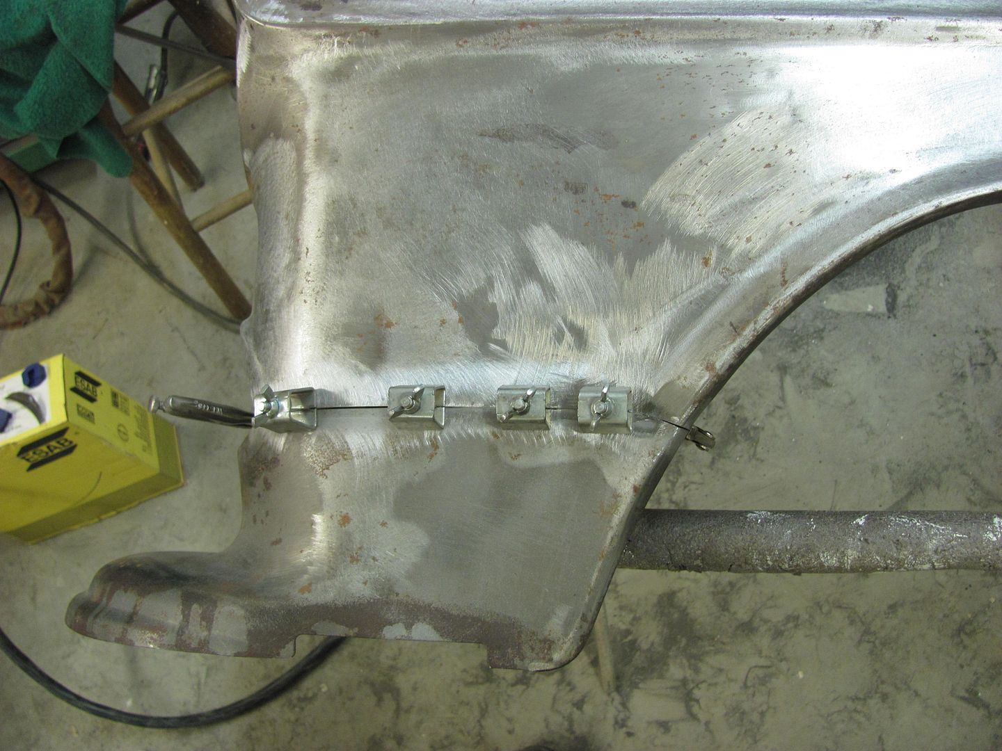
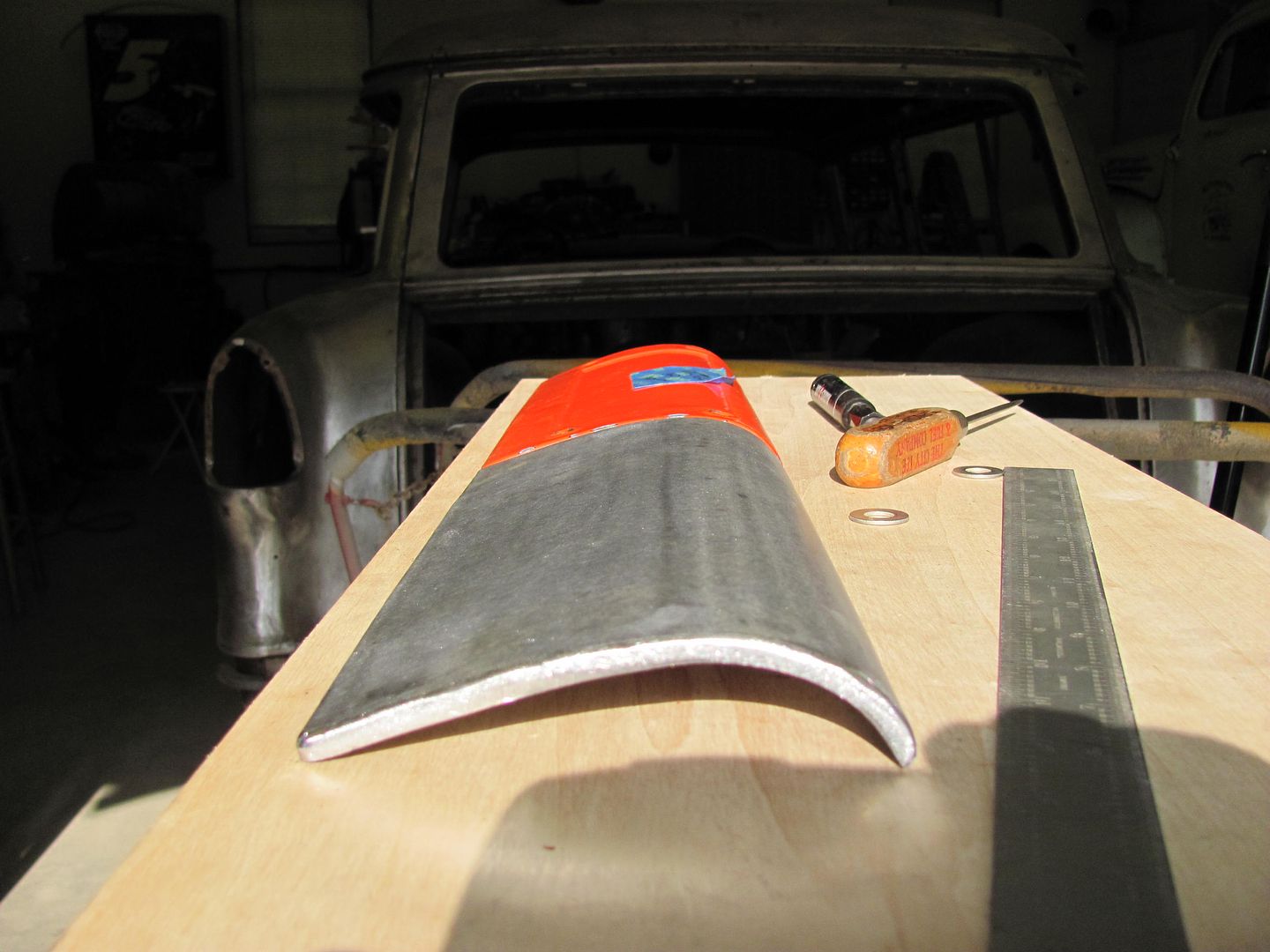
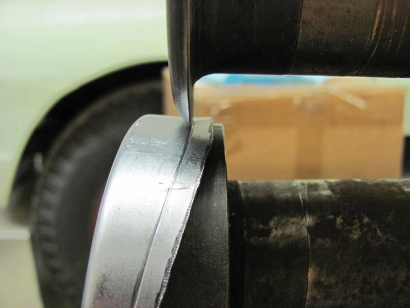
Trimmed for tight fit. Note that **** weld clamps are used to hold for fitment only, joint will be butted tight when welding...
until next time....
Continuing on the driver's fender, the top of the seam was trimmed....
When trimming along through the center, I noticed a weak spot....
This is where some dirt had been trapped behind the bolting plate on top of the flange, and looks like it wouldn't have been long in coming through paint. To be able to trim the pitted area out, the lower section was trimmed with about 3/16 extra... see the scribe mark...
Planished flat..
Clamped over fender and scribed....
Trimmed for tight fit. Note that **** weld clamps are used to hold for fitment only, joint will be butted tight when welding...
until next time....

premierplayer
Well-known member
So, I'm not a body guy ... can you provide a close-up pic of those clamps you are using?
here ya' go
http://www.ebay.com/itm/8-Piece-Set...849?pt=LH_DefaultDomain_0&hash=item4ac119d649
Kevin54
MEMBER EMERITUS
Great stuff - I know a lot of guys will get something out of it. Funny thing is, I was just debating a lathe purchase and thought: "what would I actually use one for?". Thanks for the answer!
Side note - I was watching Search & Restore this morning and was amazed at the amount of "bondo" they used. They more than "skim-coated" the entire thing and had 10 guys sanding it down. I've done a LOT of cars and several have won show awards and never have I coated an entire car in filller.....Guess I'm not as 'experienced' as Tim Strange is.

E-Tek.....I think whay they use a lot of bondo is because it's fast and easy to get the panels straight and lined up.
New cars you throw away the dented panels and put on new. The younger guys see ones like Tim Strange, and don't get me wrong, he is very talented, but the new generation of so called body men think that coating an entire car with bondo is the proper way. I've saw Boyd Coddington do it on some cars, Tim Strange, and the very first time I saw it done was on Monster Garage with Jesse James.
 I thought WTF, and figured they were doing it to just to hurry up and get the car done and painted. Those guys must really like sanding. I hate blocking out a rear quarter with hardly any filler
Another thing, ones like MP&C, you, and the few of the rare ones left, actually know how to do actual body work on an older car. When MP&C is done with that '55, it will last for years and year to come. I just wonder how many of the bondo boats out there will have large chips on the edge of a body panel or cracks under the paint? The other thing, most don't want to pay for work like that, other than a higher end collector.
My dad started teaching me when I was around 11 or 12 how to repair dented metal, and how to paint at 13. My dad was the main body and paint guy at Miller-Meteor and Superior Coach working on the hearses and ambulances, and had his own bodyshop for years when he was younger. My dad had made a pretty good name for himself when it came to doing car repairs and painting. I was lucky enough to learn a lot of the tricks from him. I don't know which I liked better, the body work or the painting. I guess I would have to say painting because I ended up doing most of it when dad got to the point he couldn't even be around paint fumes anymore. Just walking around a car an hour or so after it was painted would lay him up for a couple weeks. All the years of painting and 2 or 3 pack a day smokes took it's toll, although he made it to 95.
A problem I find now though for me, is for one, it's hard for me to do a few things one armed, but bigger than that, when it comes to painting, is intimidation. The last thing I did was my orange truck which turned our great, but I find myself being hugely intimidated for some reason, and don't know why. I guess it's called "losing your mojo"
But ones like you guys, I can sit and read through the threads for hours. I think it's great to see something going from "Trash to Treasure". So make sure you keep posting up the pics and threads.
MP&C......this question is for you.....Is that your '55 or a customers? I guess I could read back through but it's easier to ask.
Either way, I know it's a '55 Wagon, but have you ever though about changing the rear wheel openings to one like a Nomad instead of the Wagon? I think the low flat openings on the wagons just take away from the looks of the car.

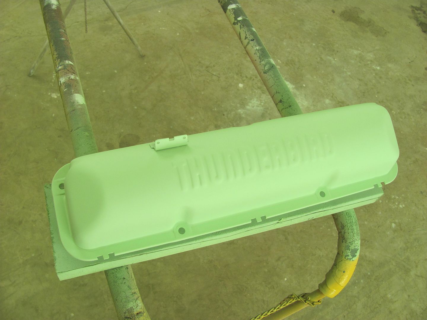
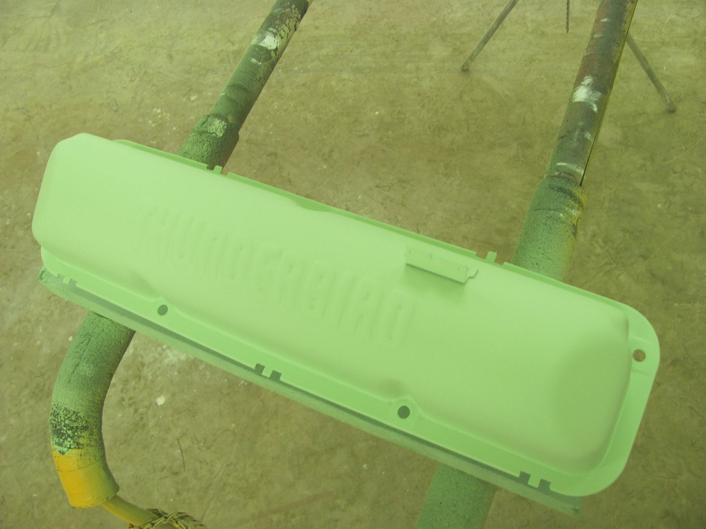
We had a couple sand-throughs on the valve covers, so some epoxy was mixed and reduced 10% to use as a sealer....
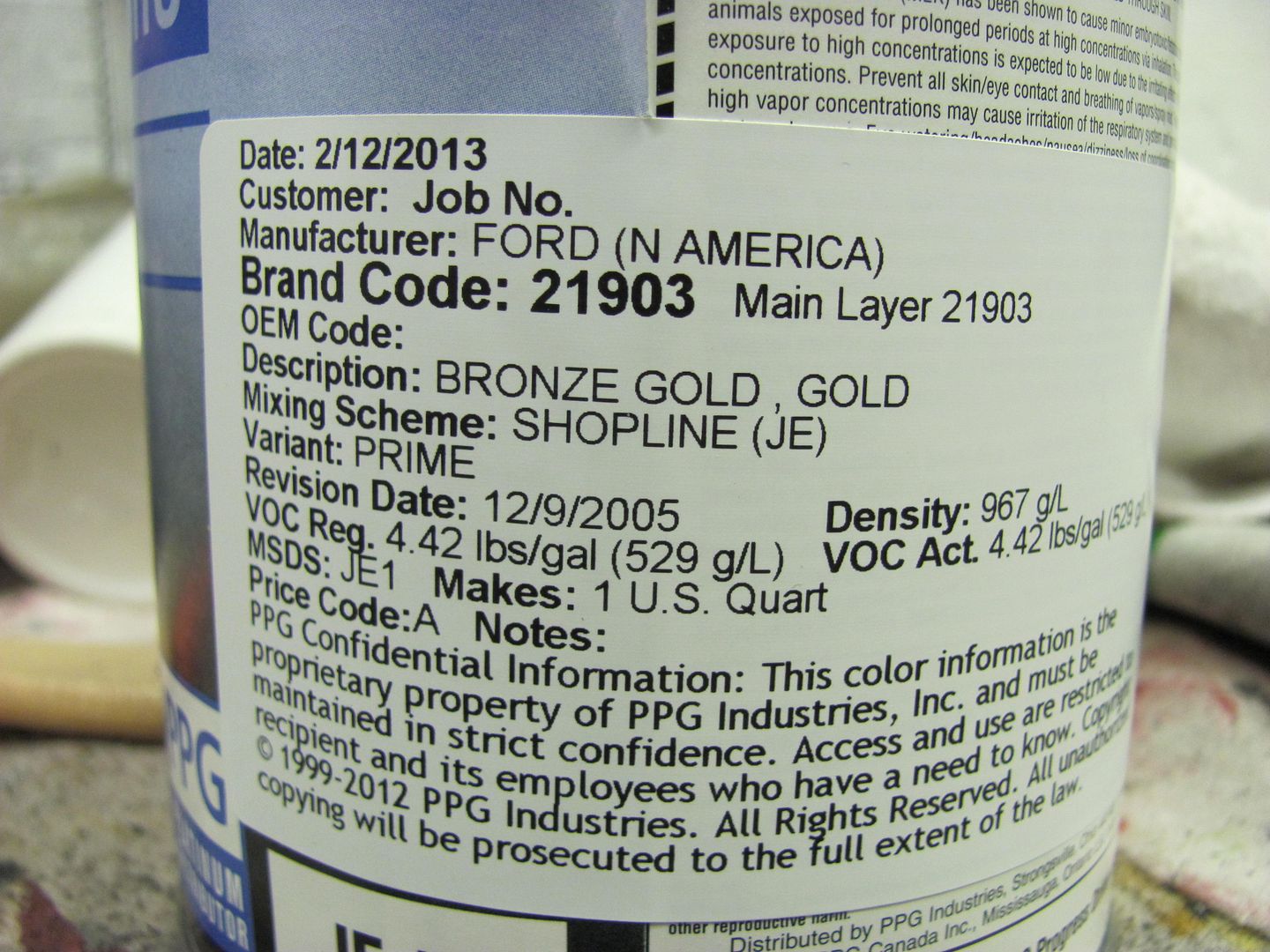
Here's the paint code for the early 60's Hi-po 390... Used acrylic enamel.
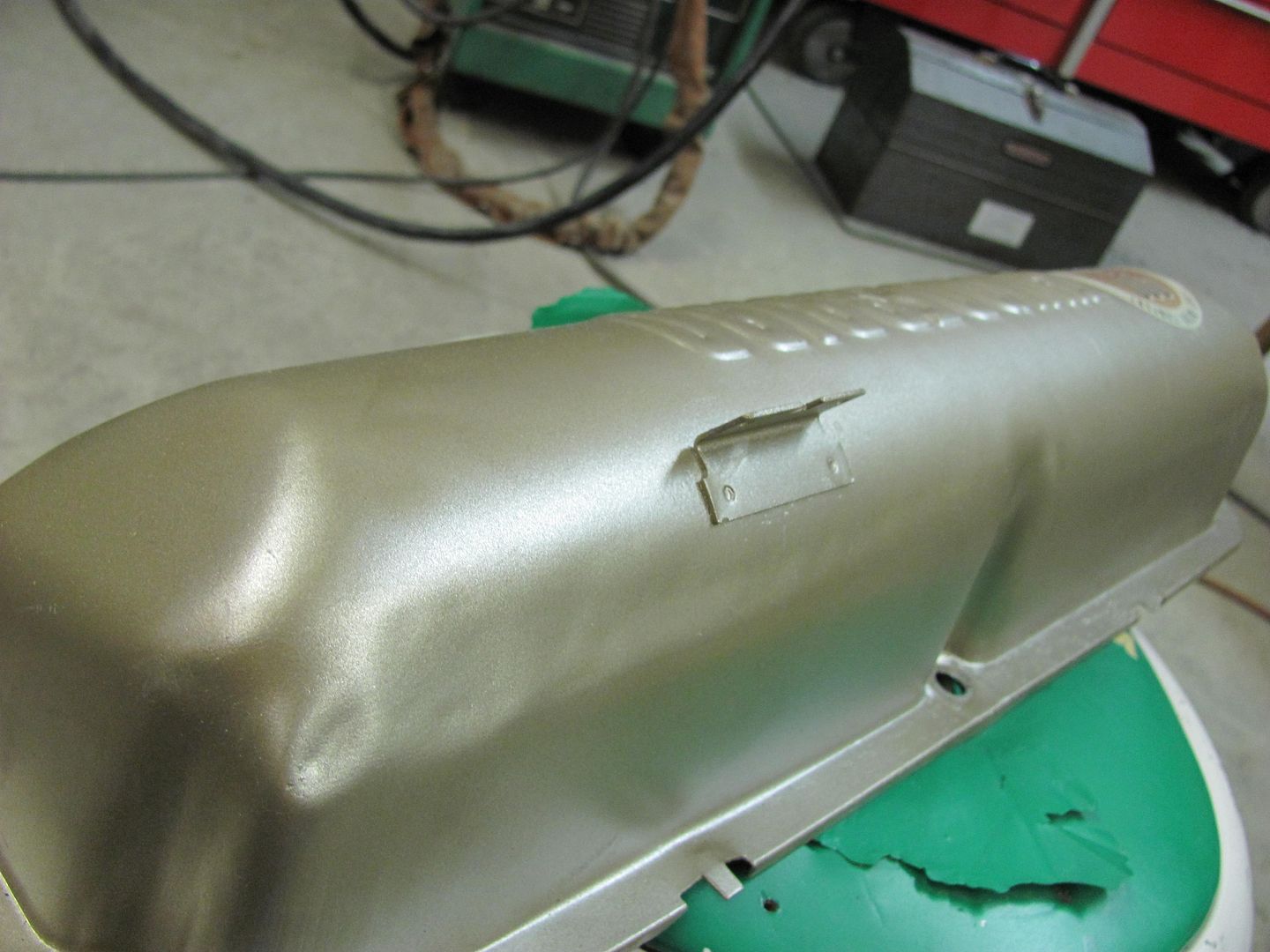
Finished up, looks quite a bit smoother than before....
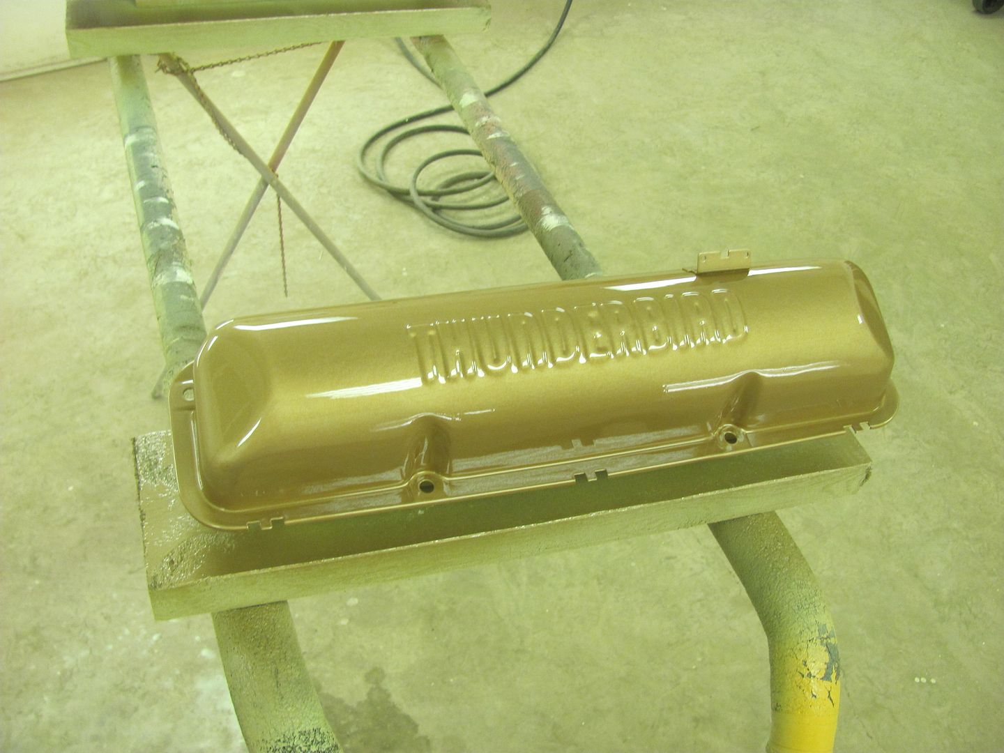
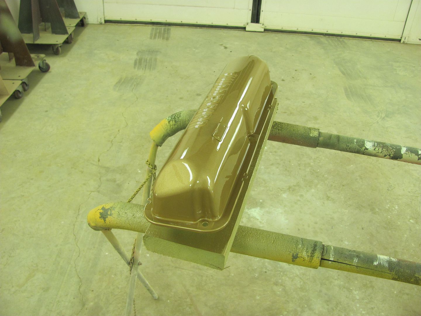
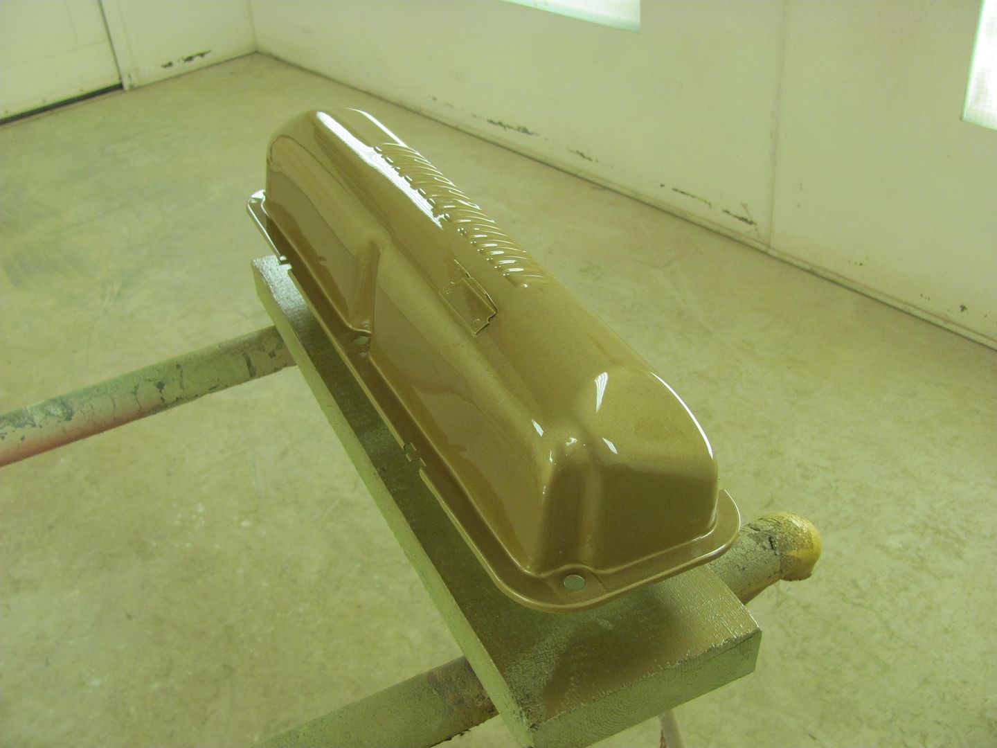
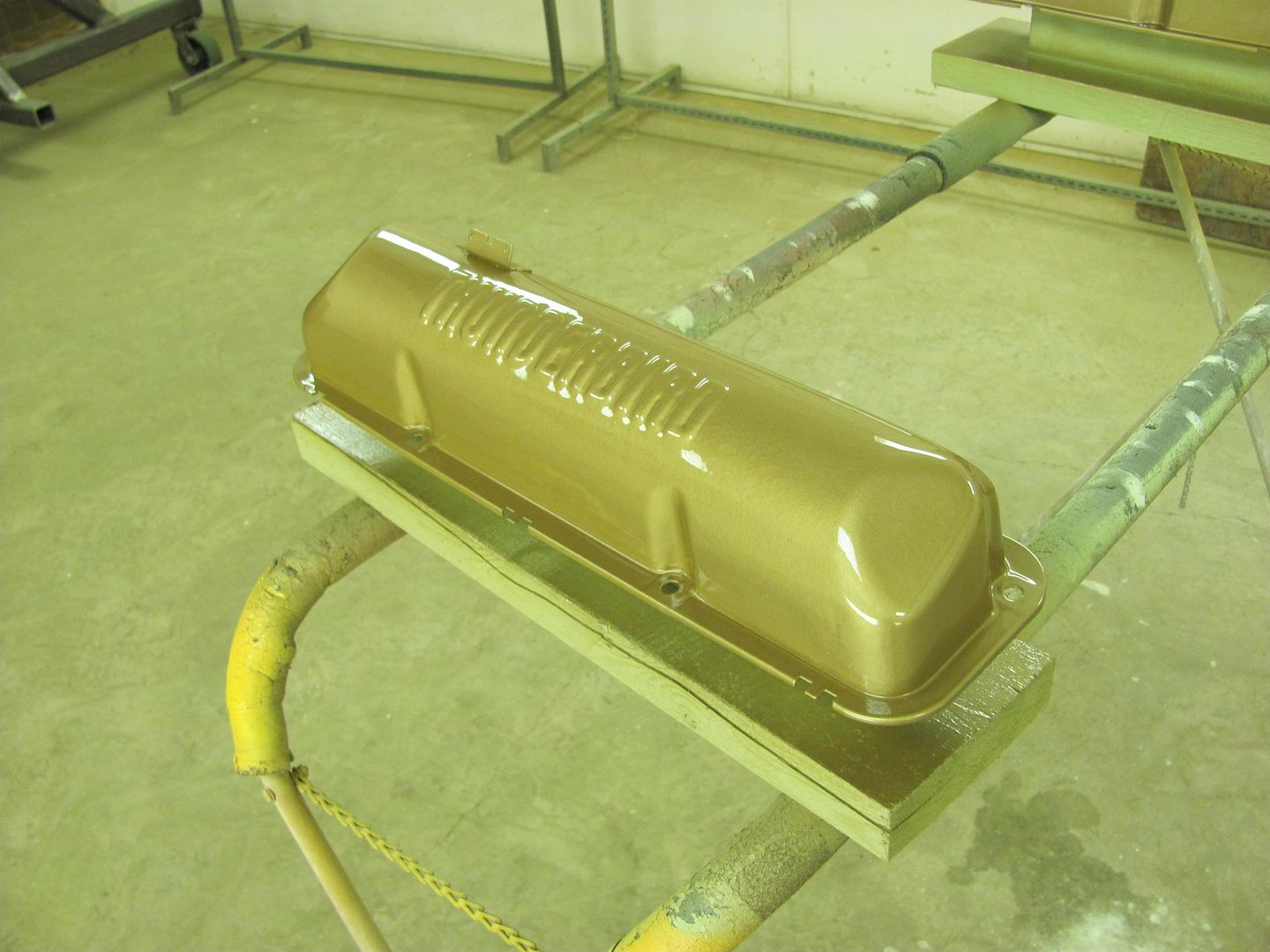
Other than wet sanding the epoxy primer, no filler used.
Here's the paint code for the early 60's Hi-po 390... Used acrylic enamel.
Finished up, looks quite a bit smoother than before....
Other than wet sanding the epoxy primer, no filler used.
Last edited:


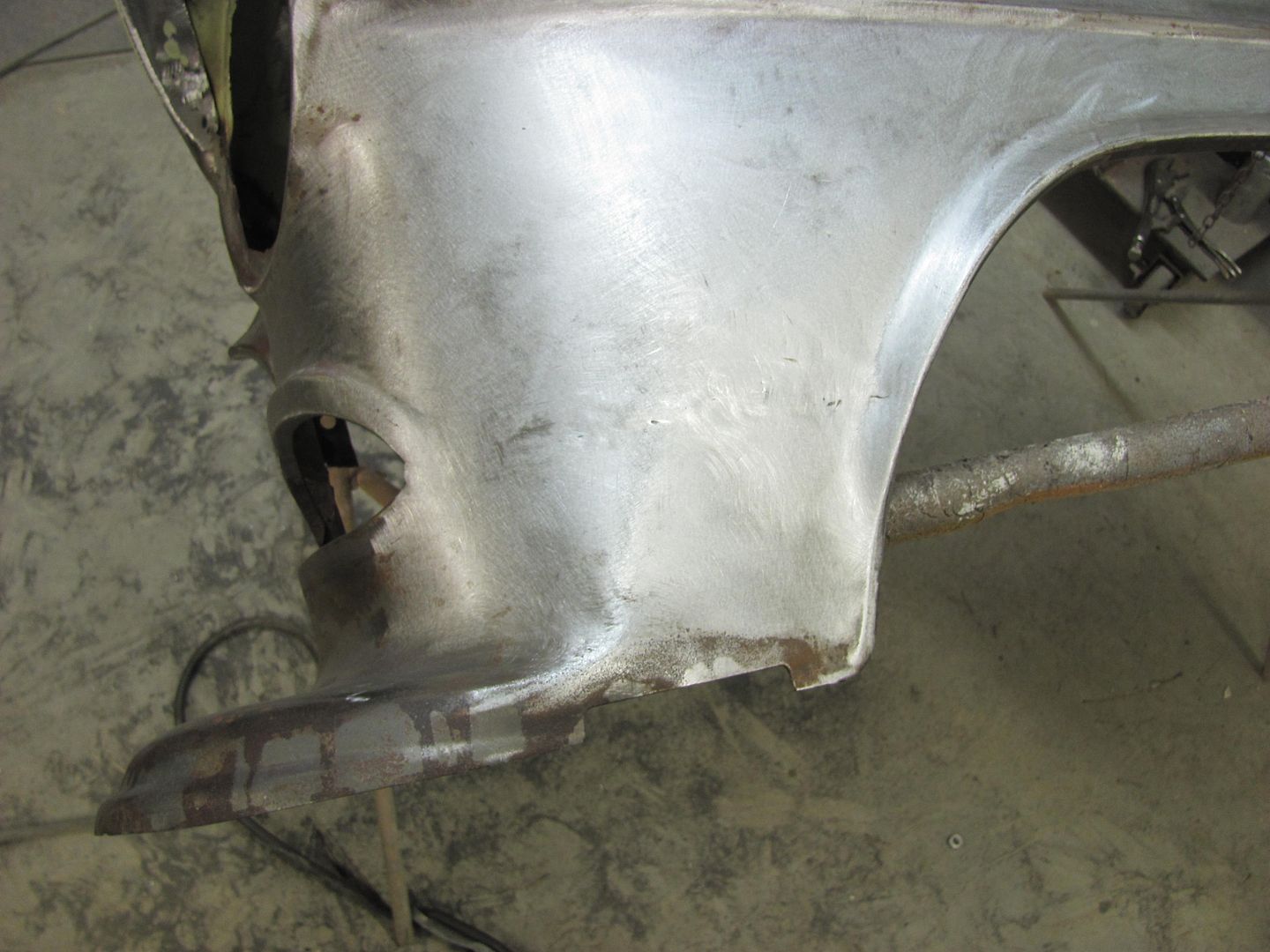
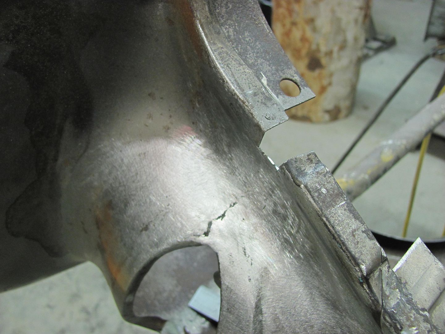
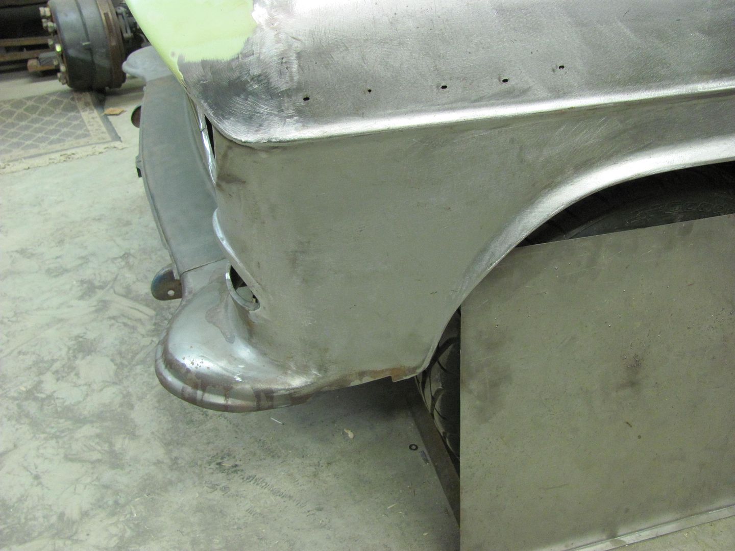
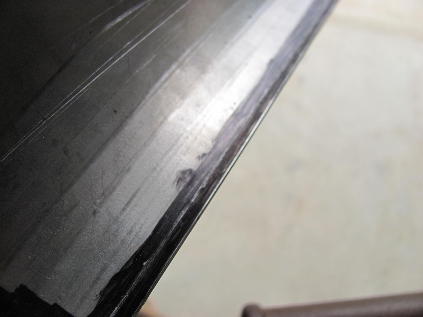
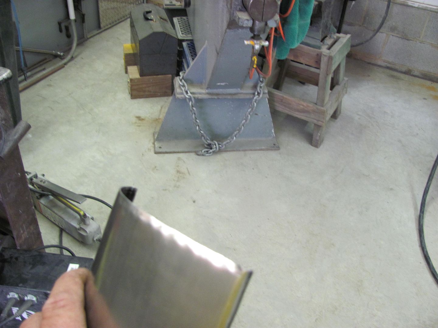
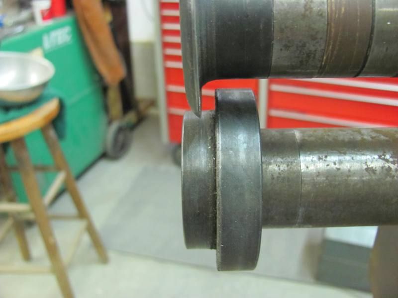
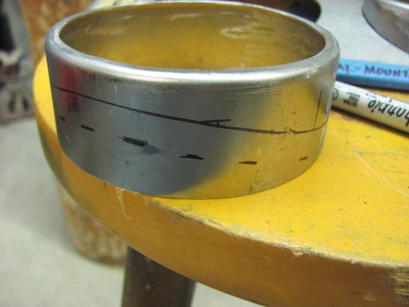
Time to get back to work on the 55's driver fender. The two pieces have been trimmed for a tight **** joint, shown here clamped together...
It was then I noticed the crease just above the seam..
Ahhh, the dreaded fender bump. I believe this is caused by someone bumping into something with the corner of the bumper, which in turn forces the lower portion of the fender backward, thus forming the inward crease (red line) and outward crease (yellow line). Always better to fix the body damage before attempting to weld panels together.
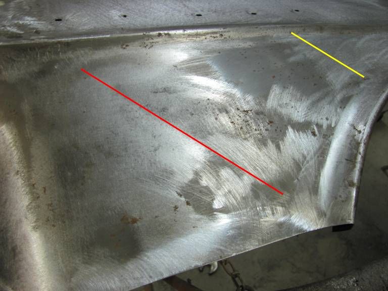
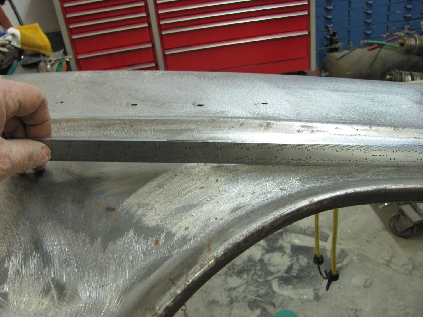
Another view of the outward crease....
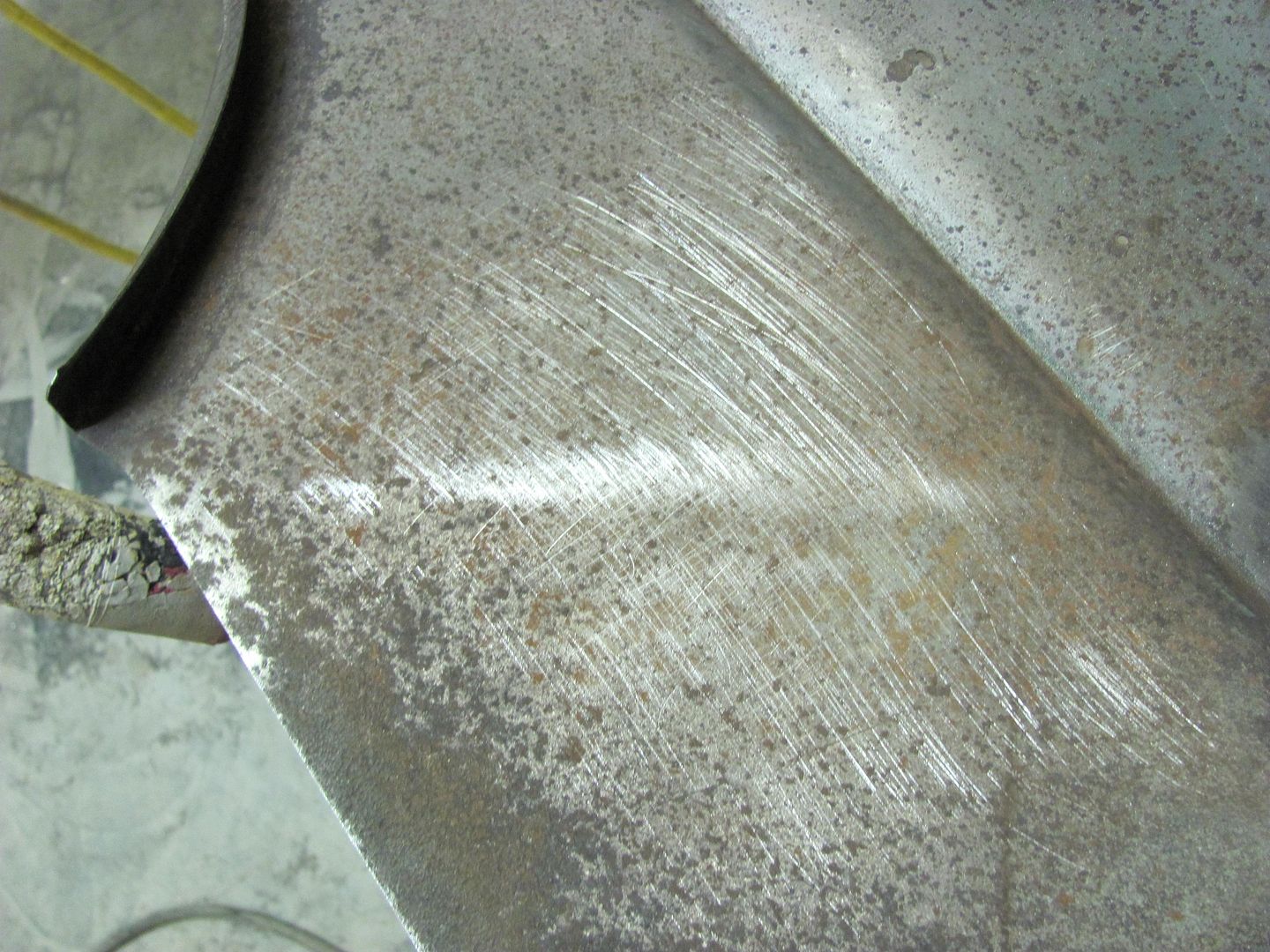
A 3" roloc disc scuffed across the lower crease on the inside of the panel quickly shows the area that needs to be bumped outward...
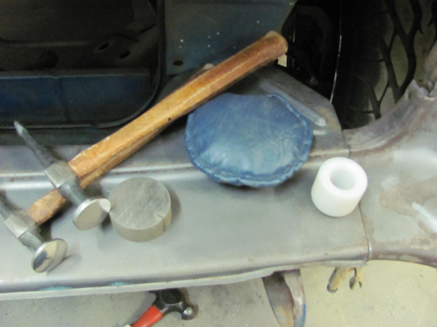
The tools used will be the donut dolly, a small shot bag, and body hammer.
The area was worked using the hammer and dolly, with progress checked by scuffing with the roloc disc.

Needs just a bit more bumping, but shows a much more repectable crown, as shown by the #32 sweep
It was then I noticed the crease just above the seam..
Ahhh, the dreaded fender bump. I believe this is caused by someone bumping into something with the corner of the bumper, which in turn forces the lower portion of the fender backward, thus forming the inward crease (red line) and outward crease (yellow line). Always better to fix the body damage before attempting to weld panels together.
Another view of the outward crease....
A 3" roloc disc scuffed across the lower crease on the inside of the panel quickly shows the area that needs to be bumped outward...
The tools used will be the donut dolly, a small shot bag, and body hammer.
The area was worked using the hammer and dolly, with progress checked by scuffing with the roloc disc.
Needs just a bit more bumping, but shows a much more repectable crown, as shown by the #32 sweep
Last edited:
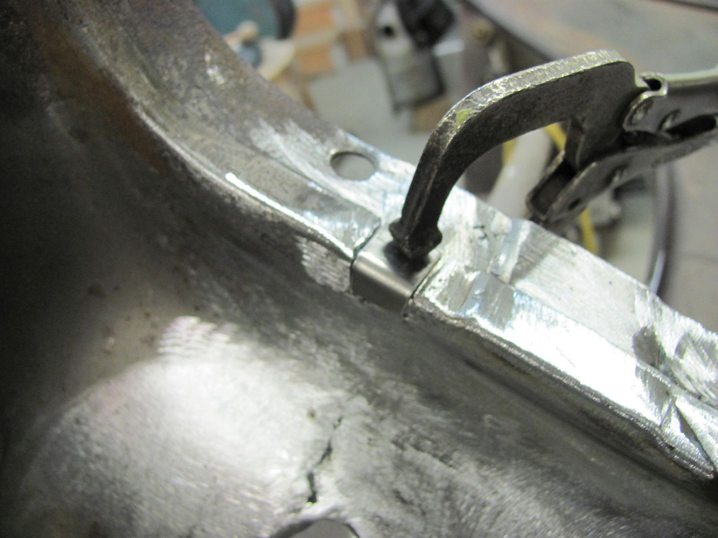
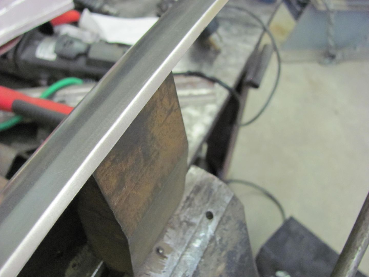
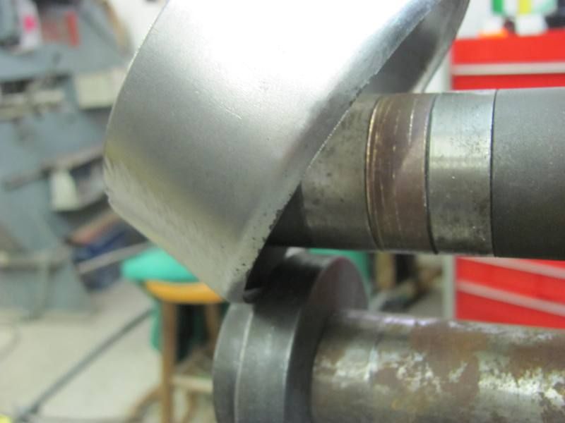
Back to welding... All clamped up, again...
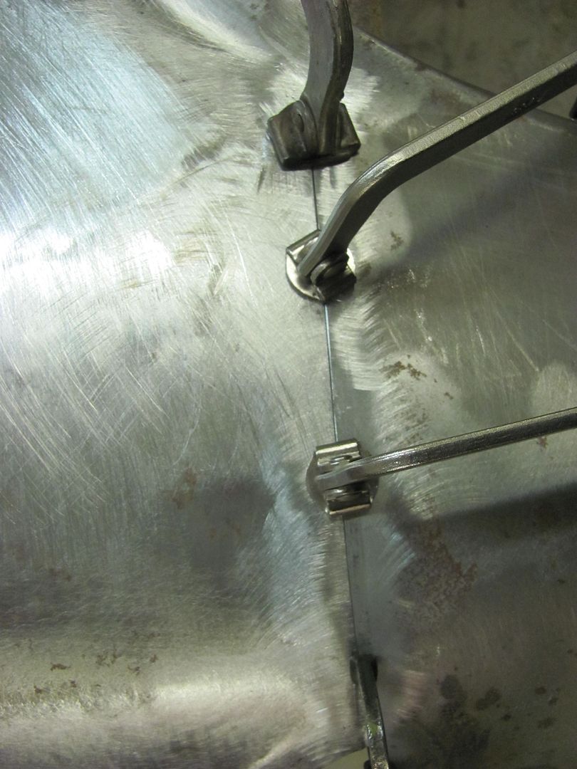
First set of tacks...
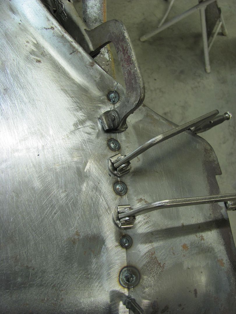
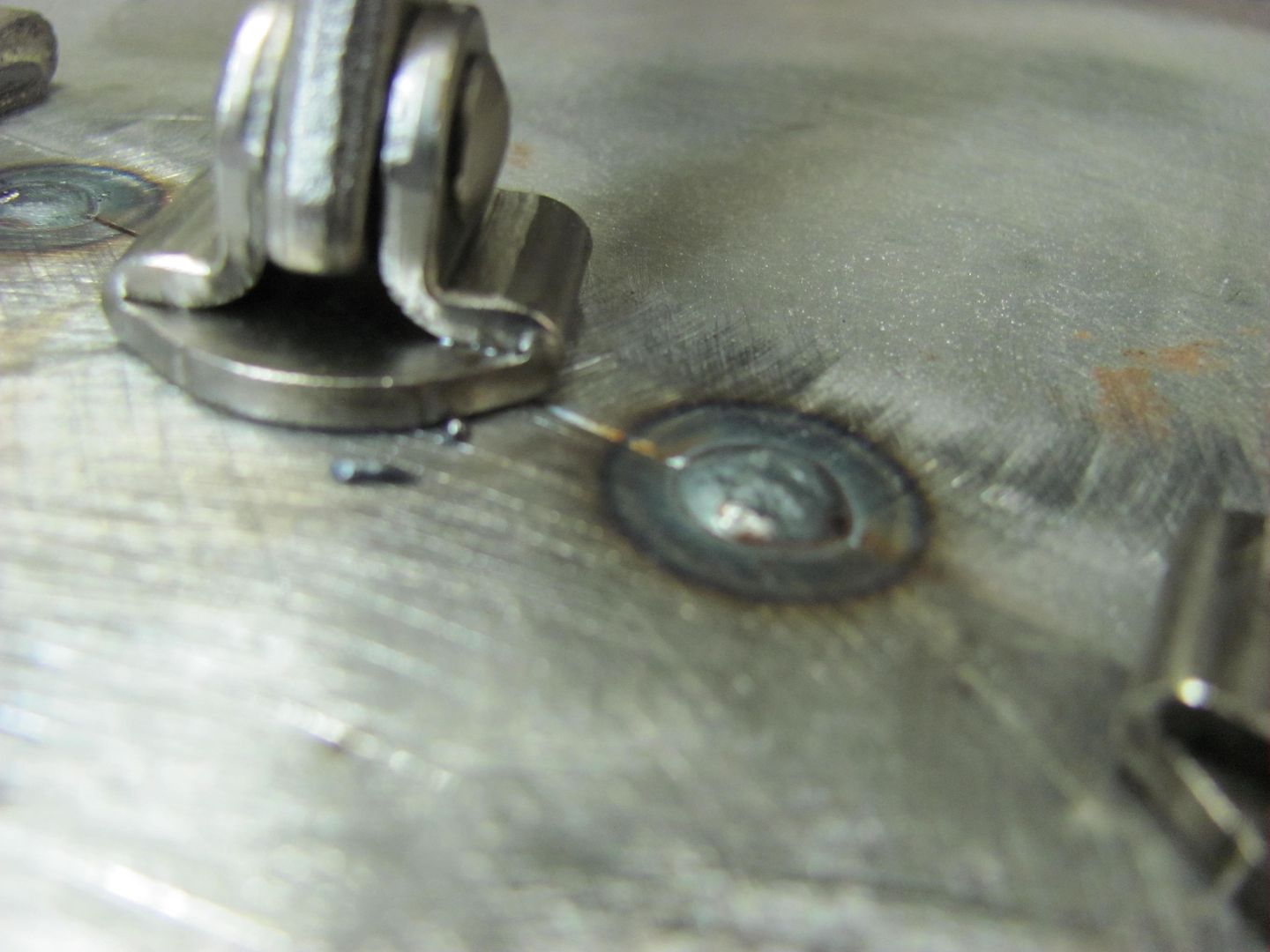
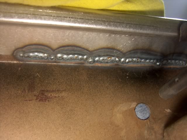
Weld penetration, the back side....
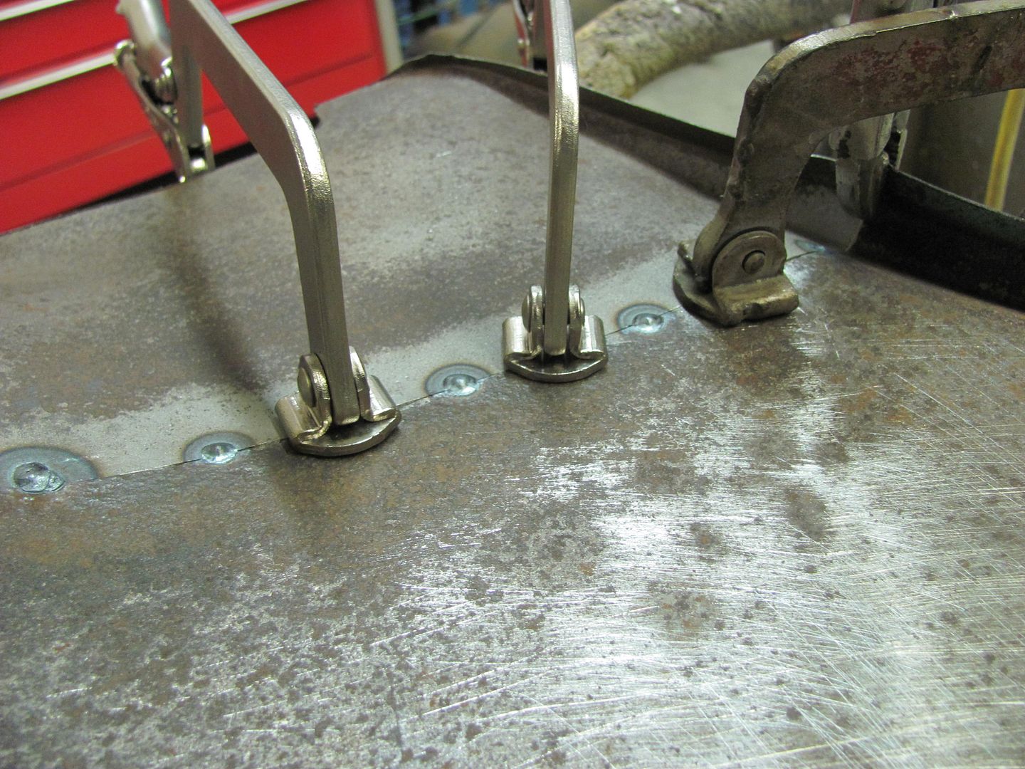
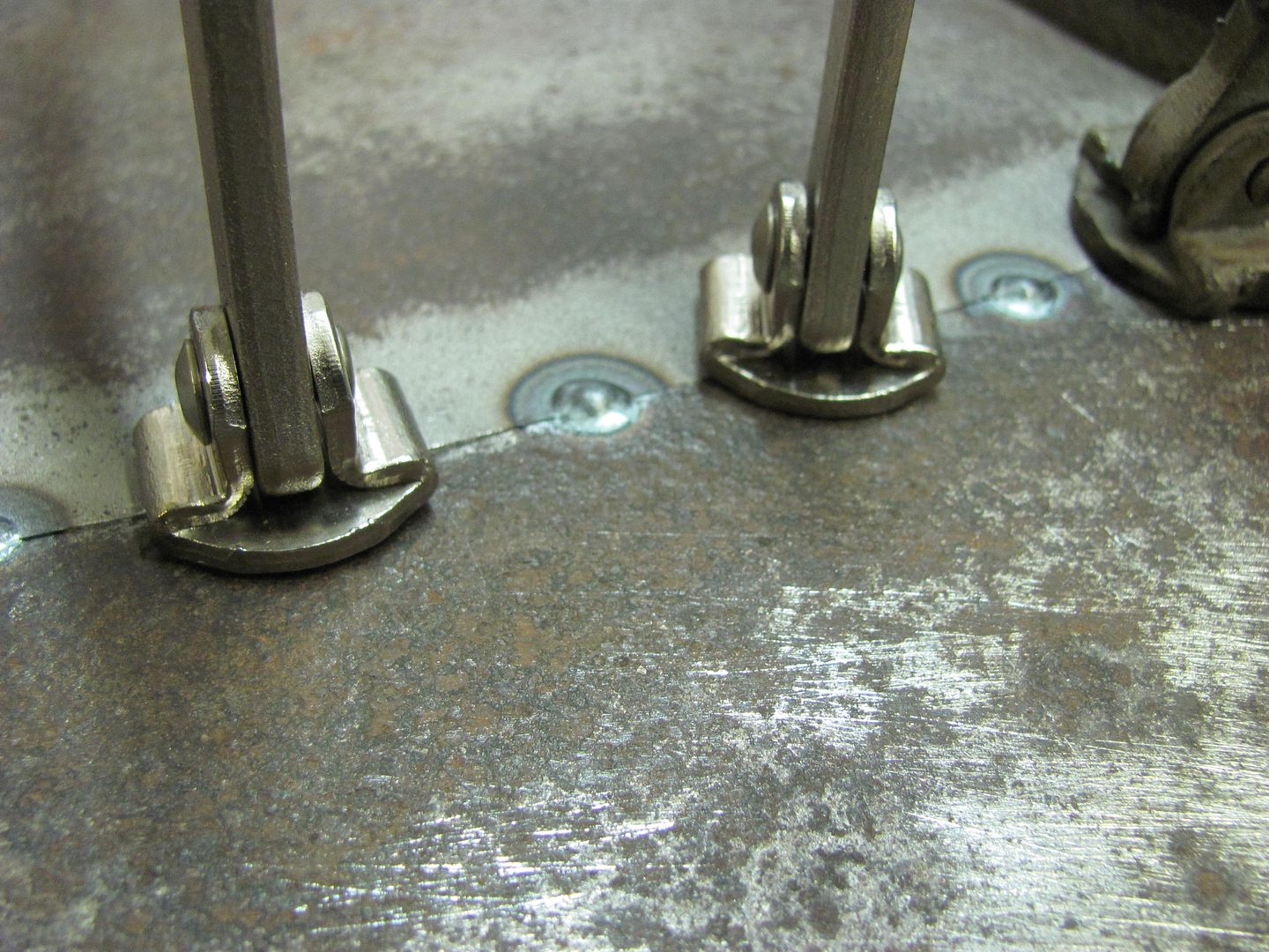
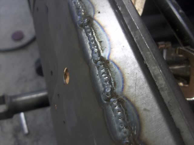
I had someone asking about the process I used with the mig, so I took the close ups to show it a little better... Weld, planish, grind, overlap, repeat...
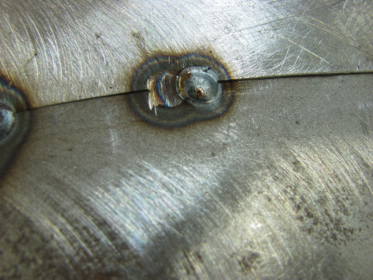
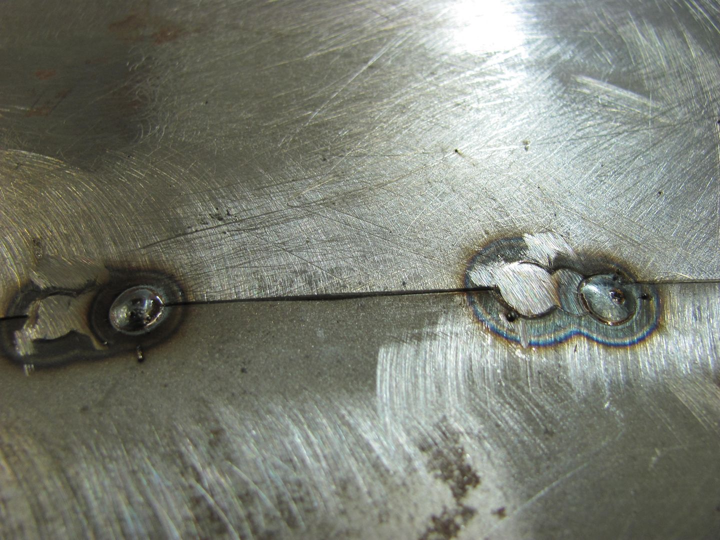
Planishing as you go helps to keep the panel's shape in check...
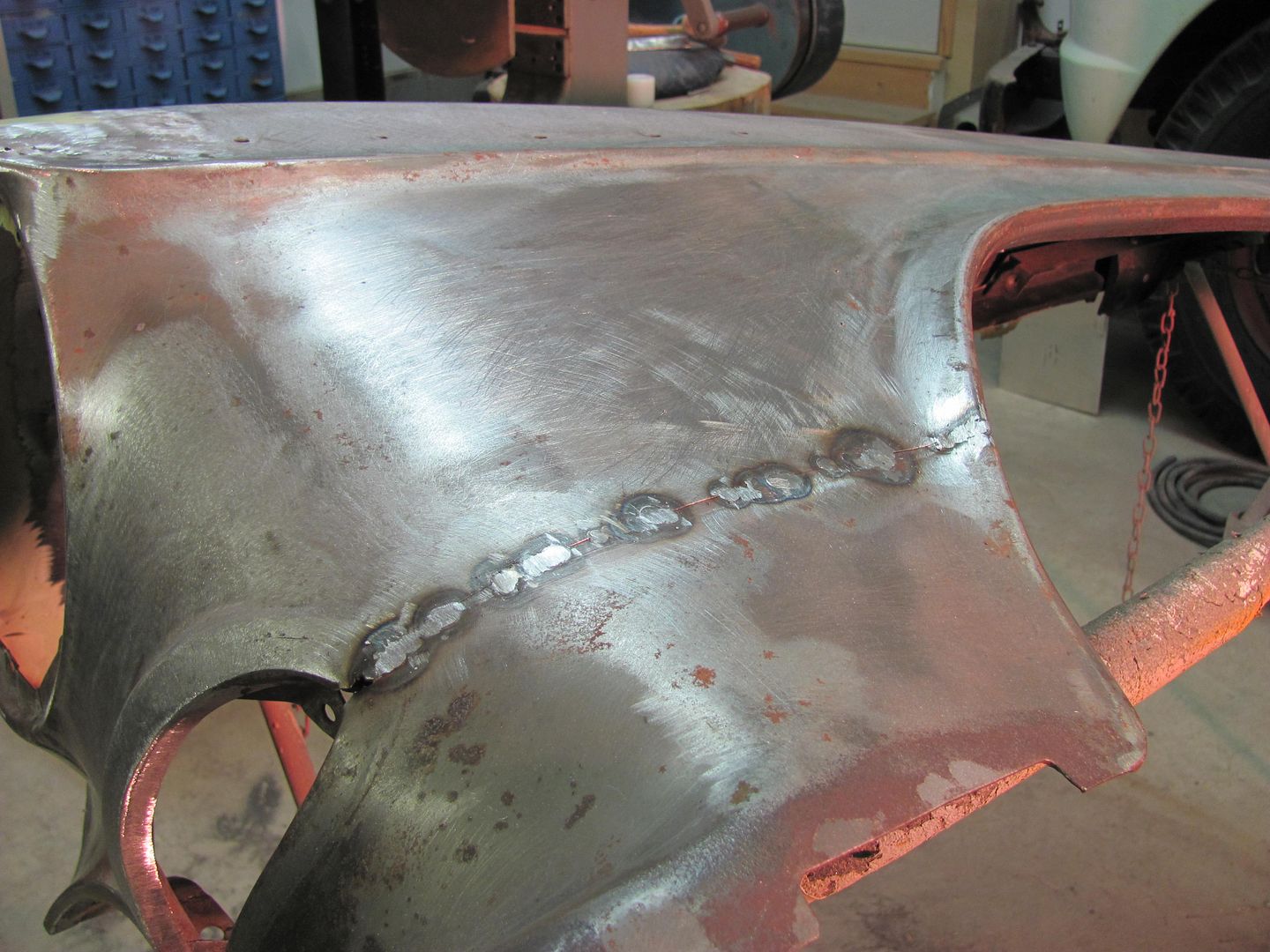
Still needs a bit of bumping but not too bad overall..
First set of tacks...
Weld penetration, the back side....
I had someone asking about the process I used with the mig, so I took the close ups to show it a little better... Weld, planish, grind, overlap, repeat...
Planishing as you go helps to keep the panel's shape in check...
Still needs a bit of bumping but not too bad overall..
Last edited:
Duck
Well-known member
I can't speak for anyone else Robert, but I'm keeping up with you and e-tek both.
Wish I'd known about this site when I started work on my Torino, I've learned quite a bit from following you fellers.
Ya'll keep up the good work.
I, for one, appreciate you and Ed taking the time to post and explain this stuff.
Duck
Wish I'd known about this site when I started work on my Torino, I've learned quite a bit from following you fellers.
Ya'll keep up the good work.
I, for one, appreciate you and Ed taking the time to post and explain this stuff.
Duck
darkk
Well-known member
Being a tin knocker my self, *retired long ago* nice work brings a tear to my eye. I grew up in the 50's-60's when lead was still used for repair. Most metal was so thick you needed a 3lb hammer to move it. You could pick and file to your hearts content and still have plenty of metal left. If you have the gift of feel and half as much skill, lead is really easy to master. Nowadays these kids are mostly prima-donnas. Nobody wants to get dirty, no one wants to fix anything. Just buy a new one. I suppose with today's new cars that's cheaper than repairing parts. Metal, if that's what they call it is so thin now. Even a little extra time in one spot with a DA creates enough heat to warp the panel. Body repair seems to be a dying trade............sigh! Sorry I went off somewhere in ancient history dream land.....nice work, glad to see good craftsmanship is still possible.
MScott
Well-known member
Is anyone reading this stuff? Bueller? Bueller?
I'm reading every word you write, Robert. I have nothing to add, basically I'm just speachless at the quality of your work and your ability to lay it out in a way that even a complete novice like myself can understand it. I just hope I can come even remotely close to emulating your work when I begin trying some of your methods soon. You certainly set a high standard. This is better than a University education.
aafc1
Well-known member
Hi Robert, I'm watching everything but what i'm really waiting for is the 51 truck.
1971gsfan
Well-known member
I'm watching intently myself waiting for my next fix Your work is helping me with my projects trying to learn some body metal working skills I'm sure lots of us guys are watching and not posting
Your work is helping me with my projects trying to learn some body metal working skills I'm sure lots of us guys are watching and not postingterryo1965
Well-known member
Hey Robert,
Good to see your work again on GJ. You helped me out with my '57 Chevy Nomad when I was replacing the floor pans and rockers a couple years ago. Everything came out great, thanks to your help! I still have one more quarter panel and the rear deck to install then the bodywork will be done. I still refer back to pictures of your '55 for reference and inspiration. In fact, I just dug out the gas tank mounting pictures so I can use your idea. It's great to see you posting your work again, and I look forward to seeing more!
Thanks,
Terry
Thanks for the comments guys. Terry, glad it worked out for you. You'll have to do a build thread.
Well the past couple days I've traded in the body hammers for a Estwing framing hammer. My wife bought a house, and we're doing some renovations. Someone at some point thought a crapper would be a good addition to the utility room. I guess you can check on the laundry or fold some clothes while pinching a loaf.

To make the house more attractive to tenants, we decided to get rid of the oil furnace, install a new heat pump and air handler, new hot water heater, and a new bathroom off the master bedroom with a standup shower. Here's the plans...

Progress so far...

Should have the air handler closet done and ready for the HVAC guys after this weekend.
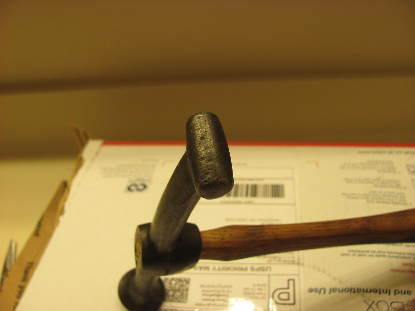
And back to more important stuff, a care package showed up today. To say it was packaged well is an understatement..

Proto 1426, which has the barrel end tip..


Well the past couple days I've traded in the body hammers for a Estwing framing hammer. My wife bought a house, and we're doing some renovations. Someone at some point thought a crapper would be a good addition to the utility room. I guess you can check on the laundry or fold some clothes while pinching a loaf.
To make the house more attractive to tenants, we decided to get rid of the oil furnace, install a new heat pump and air handler, new hot water heater, and a new bathroom off the master bedroom with a standup shower. Here's the plans...
Progress so far...
Should have the air handler closet done and ready for the HVAC guys after this weekend.
And back to more important stuff, a care package showed up today. To say it was packaged well is an understatement..
Proto 1426, which has the barrel end tip..
don long
Well-known member
Fyi Robert
I'm watchin and droolin and rememberin way back when
with that old tear in the corner of my eye
Thanks for the time spent on my behalf.
Where are you finding all these 50's and 60's hammers??
Now I'm jealous
I'm watchin and droolin and rememberin way back when
with that old tear in the corner of my eye
Thanks for the time spent on my behalf.
Where are you finding all these 50's and 60's hammers??
Now I'm jealous
I had some time this evening, so I thought I'd get the new hammer ready for use.


The handle was slightly loose, but it was a such a nice handle that I couldn't bring myself to change it out. I'm down to 3 replacements, they'll have to wait for another. I rapped the end of the handle with a dead blow to set the handle on a bit more, installed a couple wedges to keep it there, and used the band saw to trim off the excess.
Hope to get back to some metal work tomorrow..


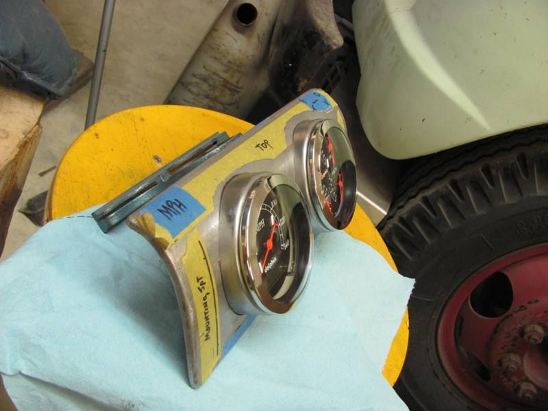
Last summer I had a local Studebaker owner stop by for some metalwork, he was revamping his dash gauge options, and needed fresh sheet metal for mounting. Details here:
A few weeks ago one of the local Studebaker owners needed some panels made for the dash of his truck (1947 M5), he's revamping the dash gauge/radio arrangement and needed some fresh metal to work with. Here's the existing:
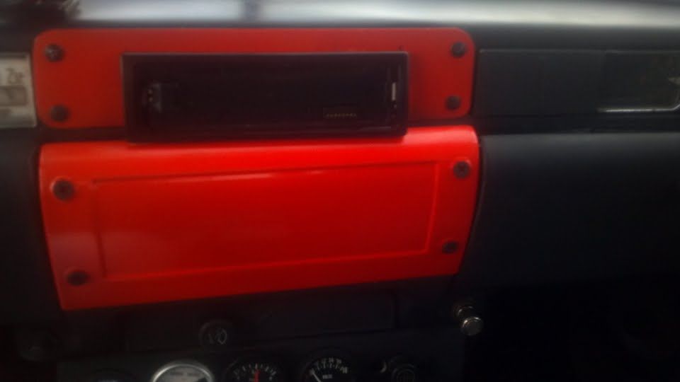
Where the factory panel has a recess, and since he has plans for installing a couple gauges in that panel, the new will be made without the recess. The flat panel above for the DIN radio will be replaced as well, with the sides tipped for uniformity.
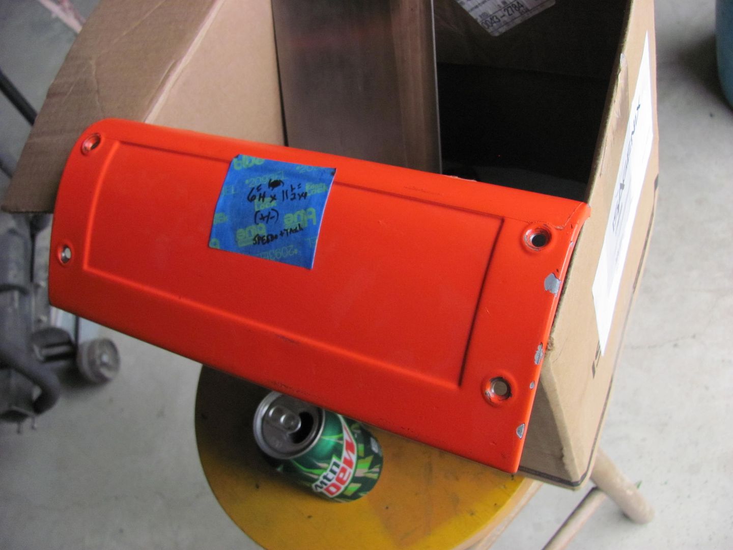
The old panel has seen some previous holes, for whatever reason.
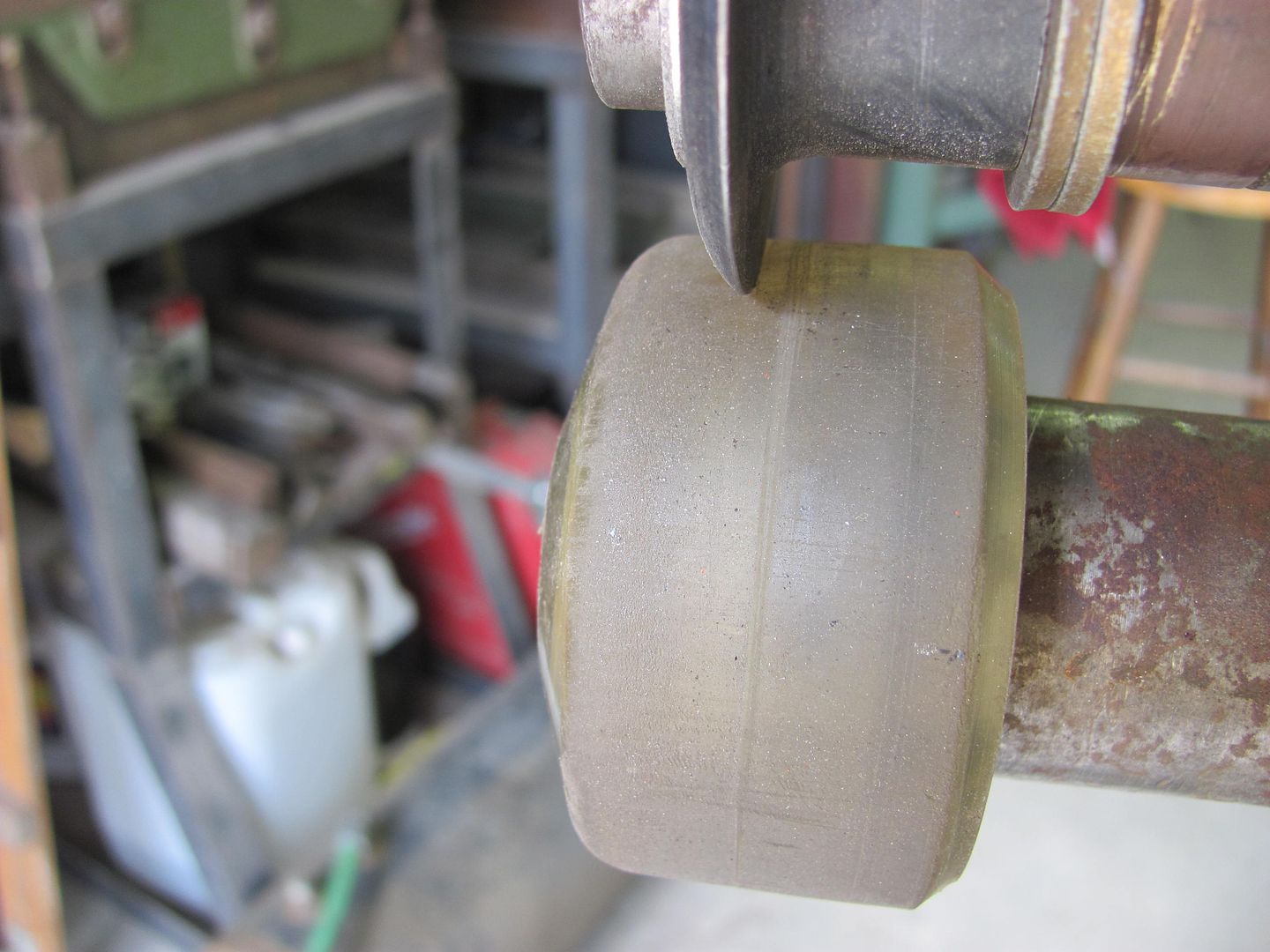
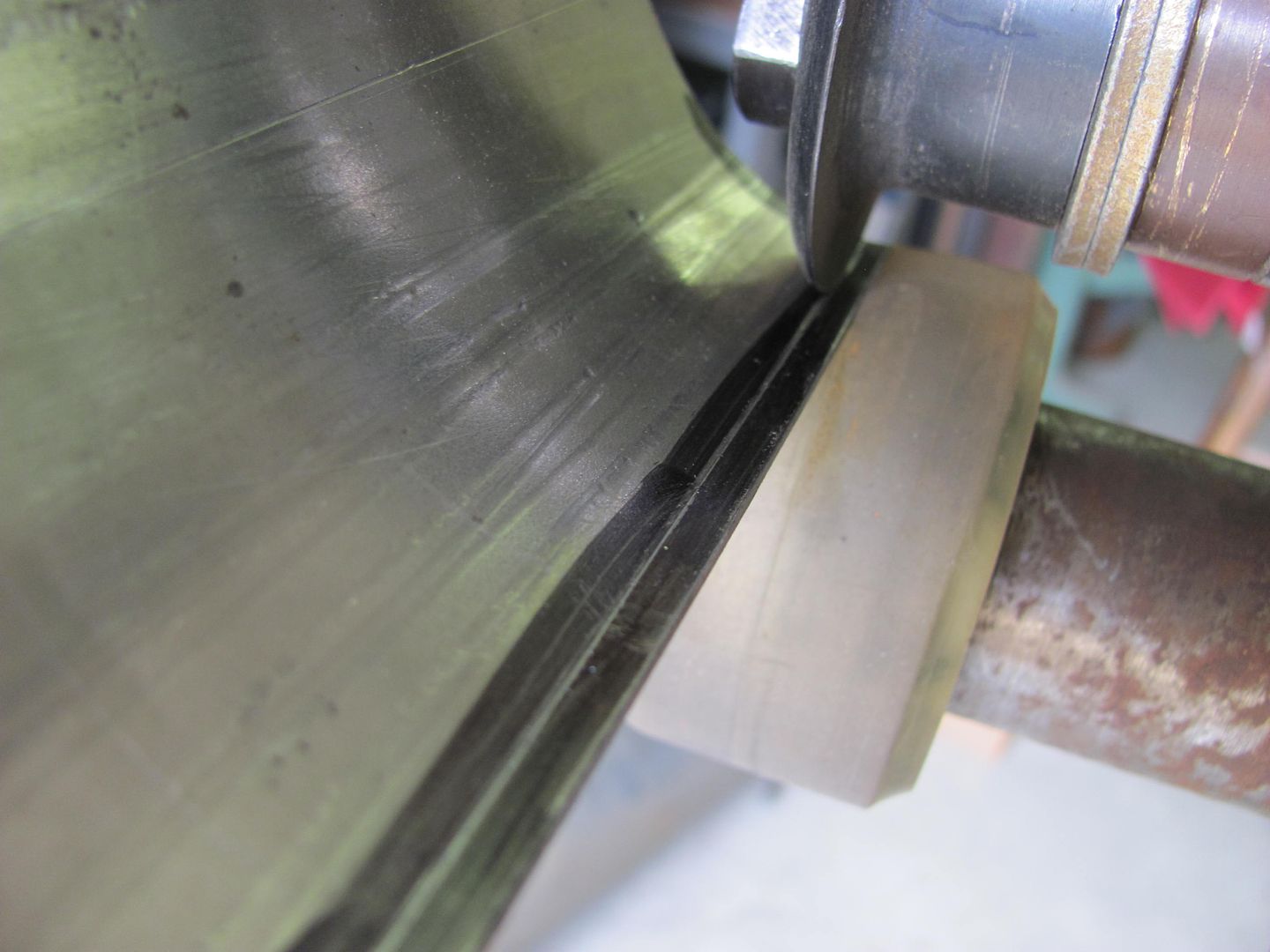
Where the rubber tire on top of the e-wheel does a nice job of forming a radius across a panel, the upper portion of the panel was a bit tighter than the 3" radius anvil will provide.
Having just set up my bead roller with the skateboard wheel for tipping, I thought to use this with a beading die to form the tighter radius.
Here's the results of "rolling" the panel
The panel has about an 1/8" lip around the perimeter, so the radius die was changed out to one for tipping.
With only just over 1/8 of extra to tip the flange, this process was not that effective. Hindsight, about 1/4 left over and trimmed afterwards would have been more effective. But since the panel matched so well, lets try other persuasive devices.
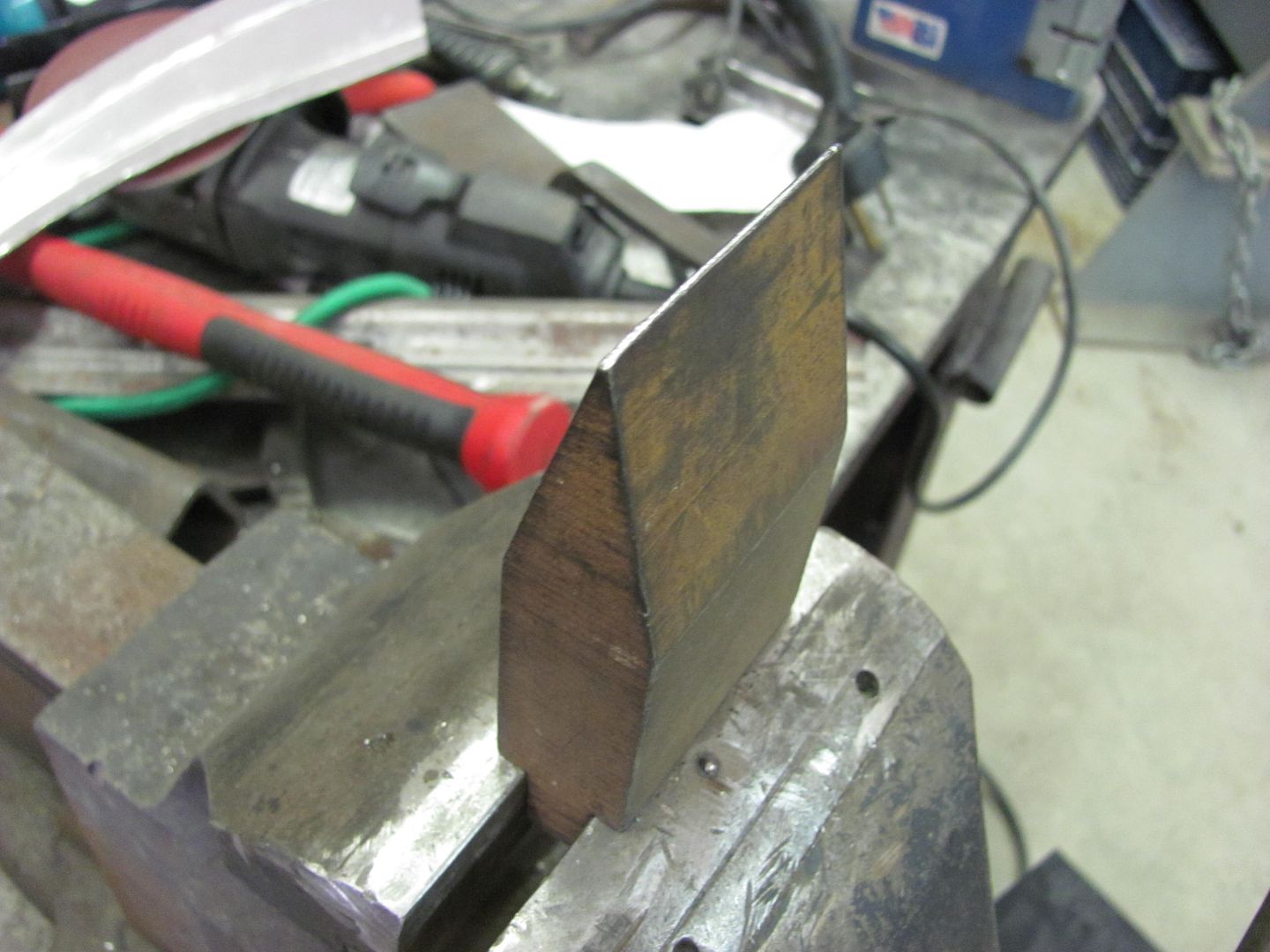
The tipping wheel did do an adequate job of marking the crease location....
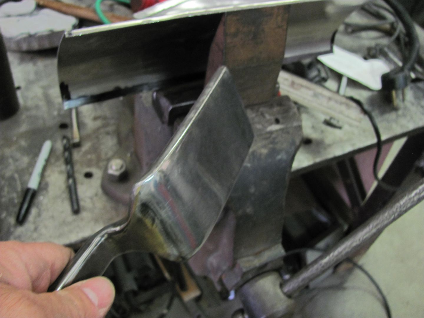
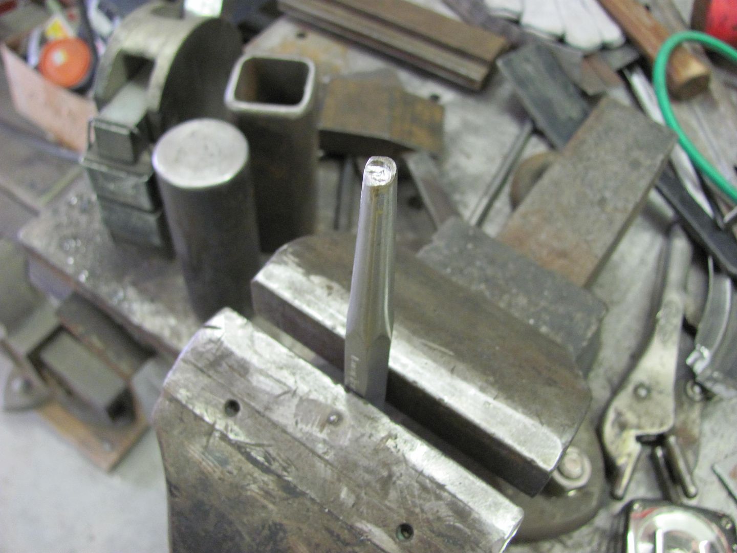
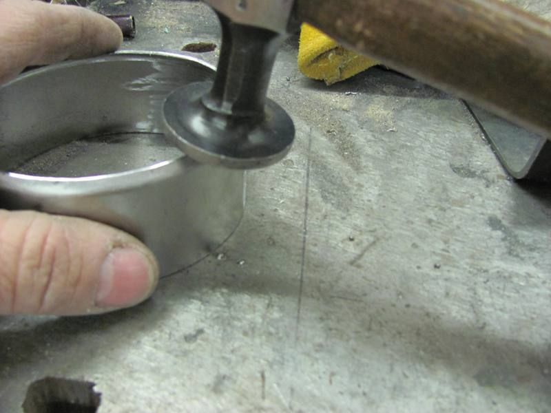
And the "vice anvil" and a ******* was used to fold the straight lip over to a 90....
A different anvil was chosen for the radiused edges...
And a punch used to form the 4 corner radiuses...
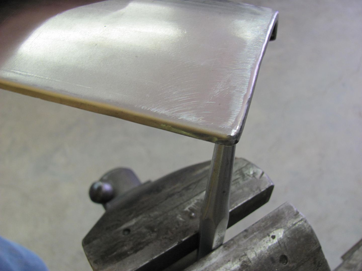
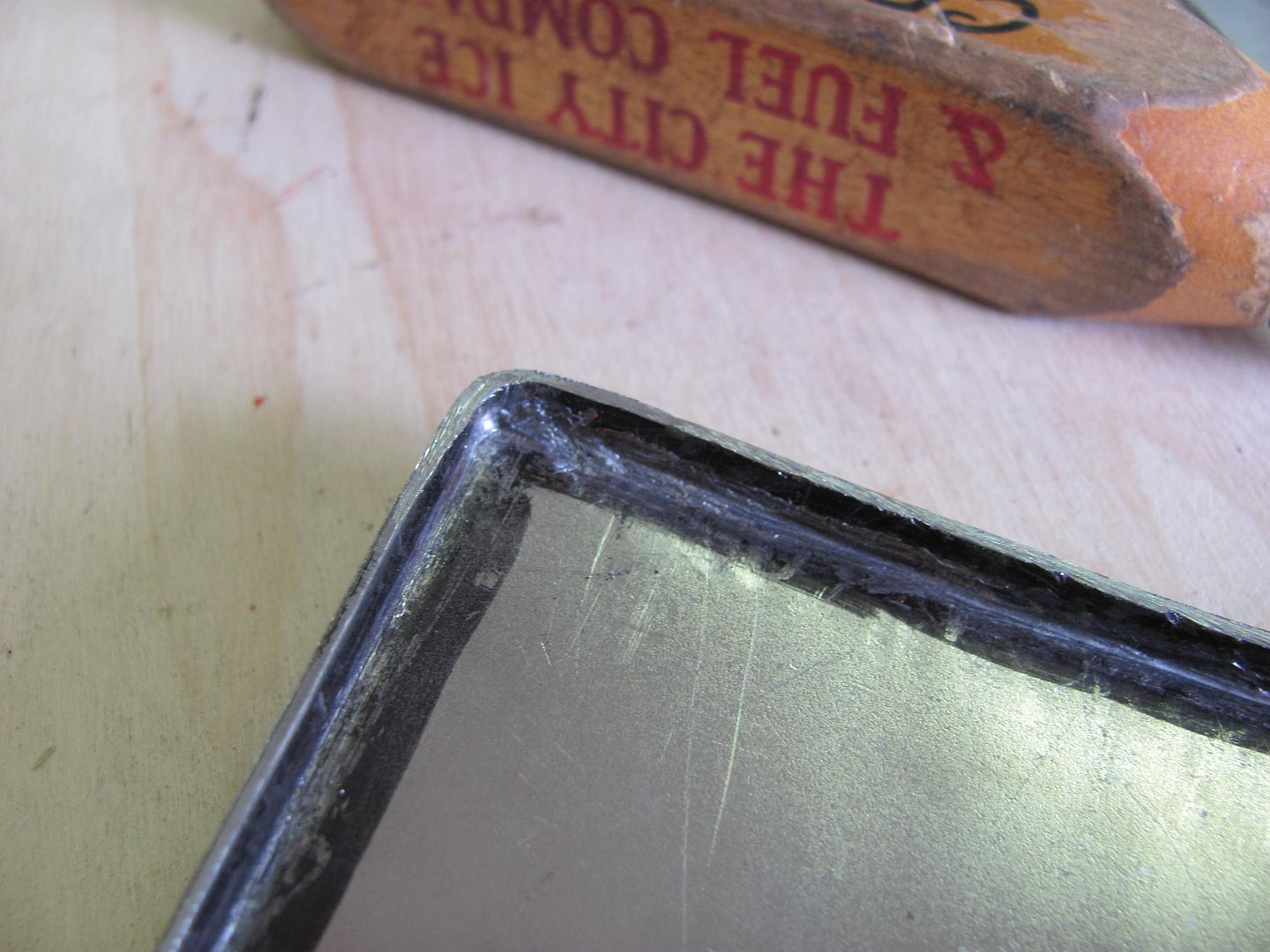
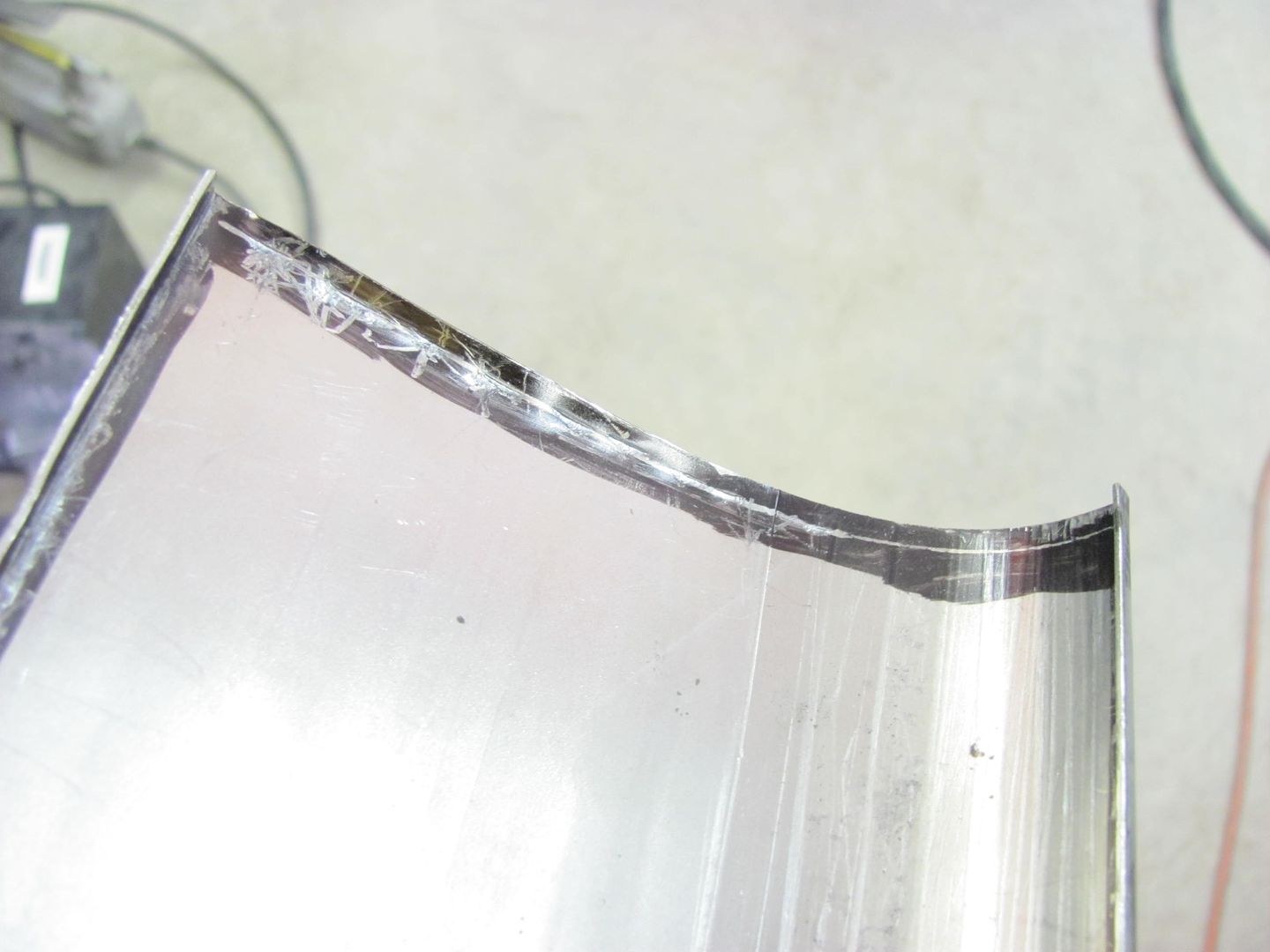
And once complete, the comparison.........
Then the same process was used for the upper plate. The folded edges on this will make it match the lower panel a bit better and make it look more as an original piece...
And the two together...
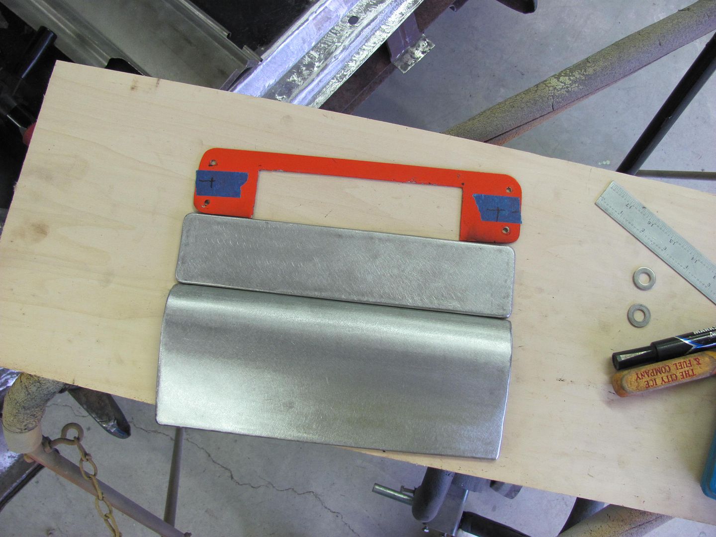
For now, we are leaving the mounting holes out. It may even get some studs welded on the back side, for a clean look. But we'll cross that bridge when we get there.
Last edited:
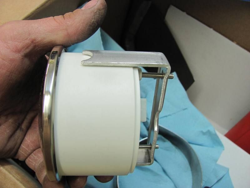
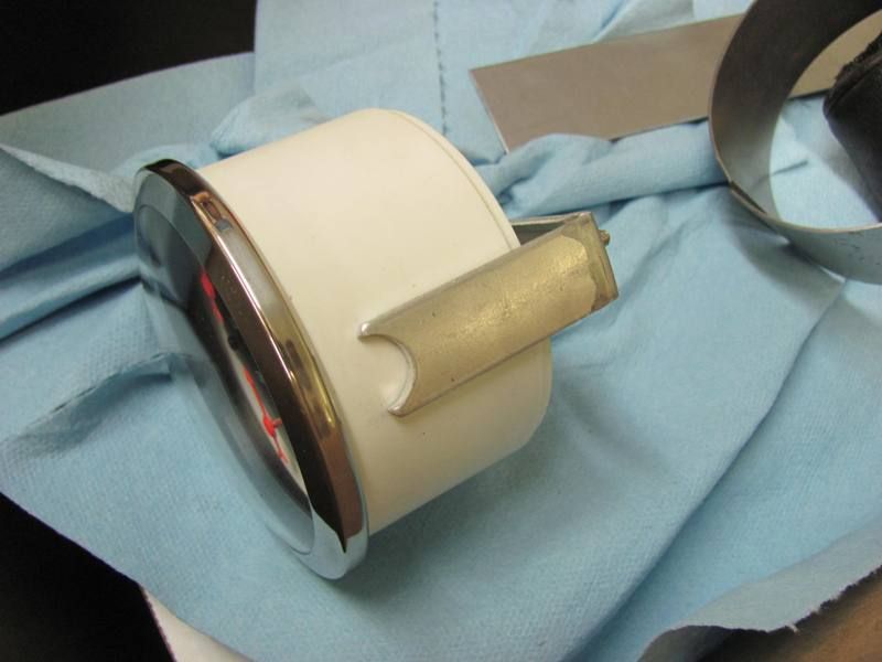
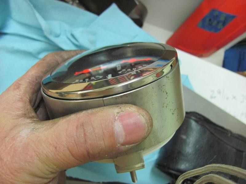
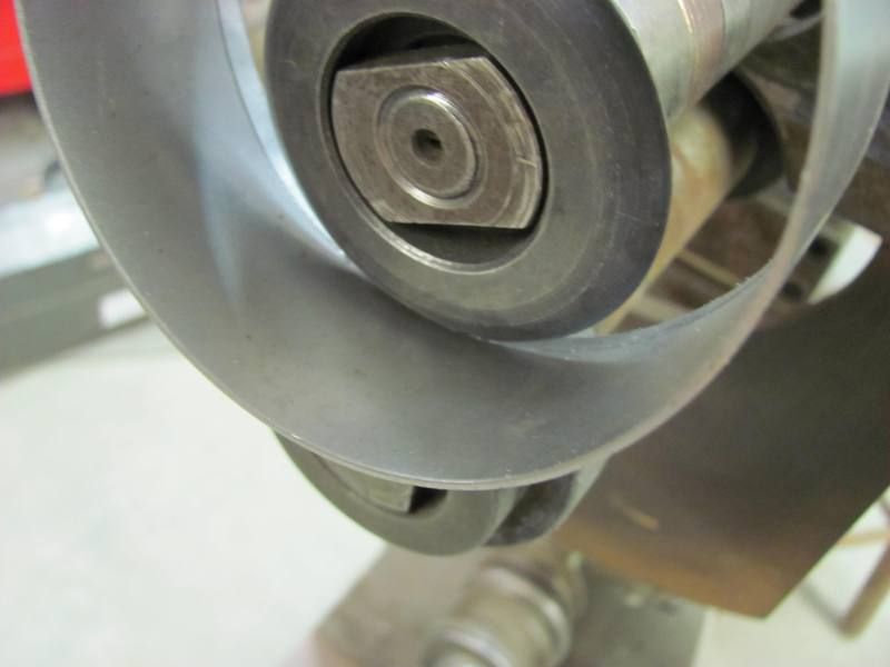
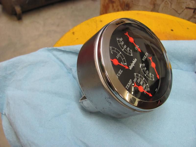
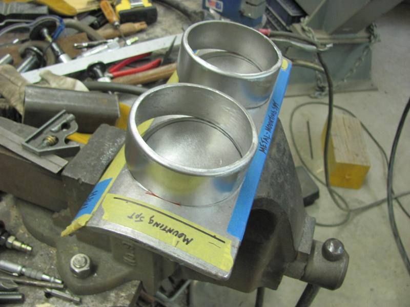
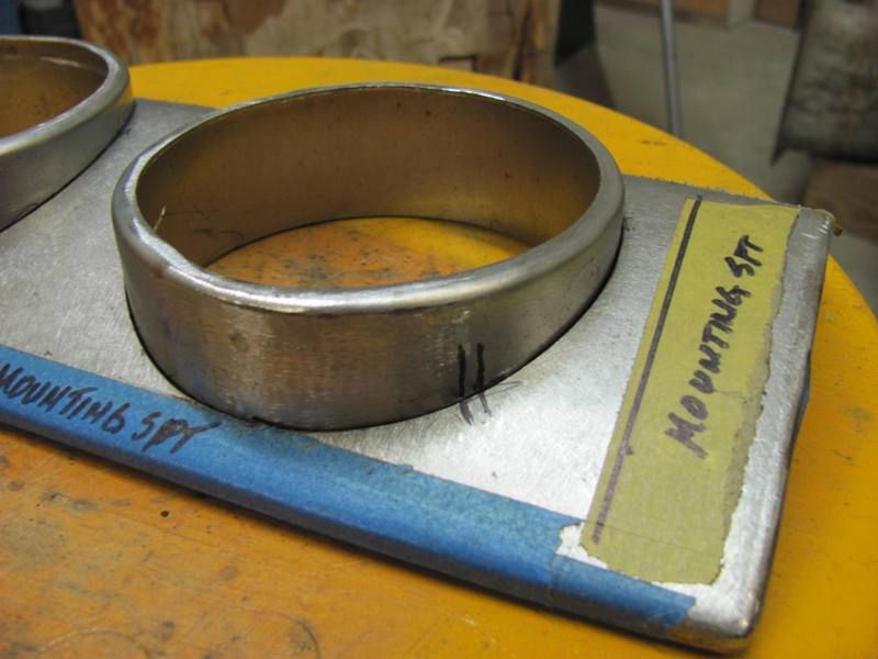
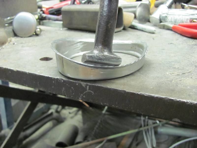
He recently stopped by with a better idea of what he planned, and a box full of gauges. As the panel for the center of the dash has a crown, we will need some adapter rings...
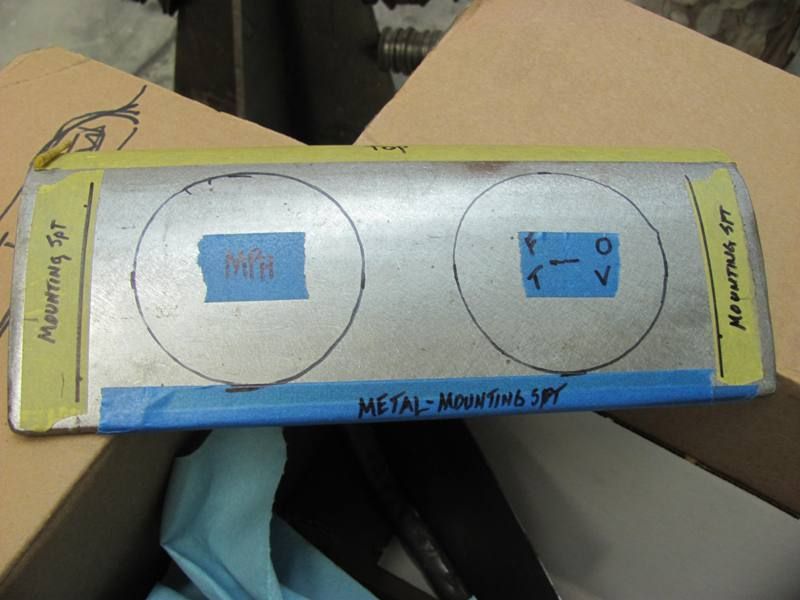
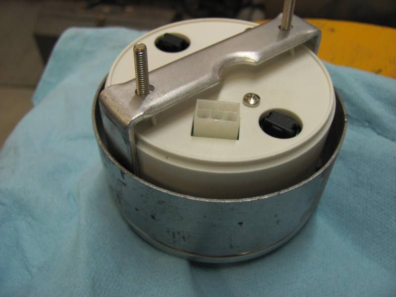
Here's the new gauge with the clamping bracket....
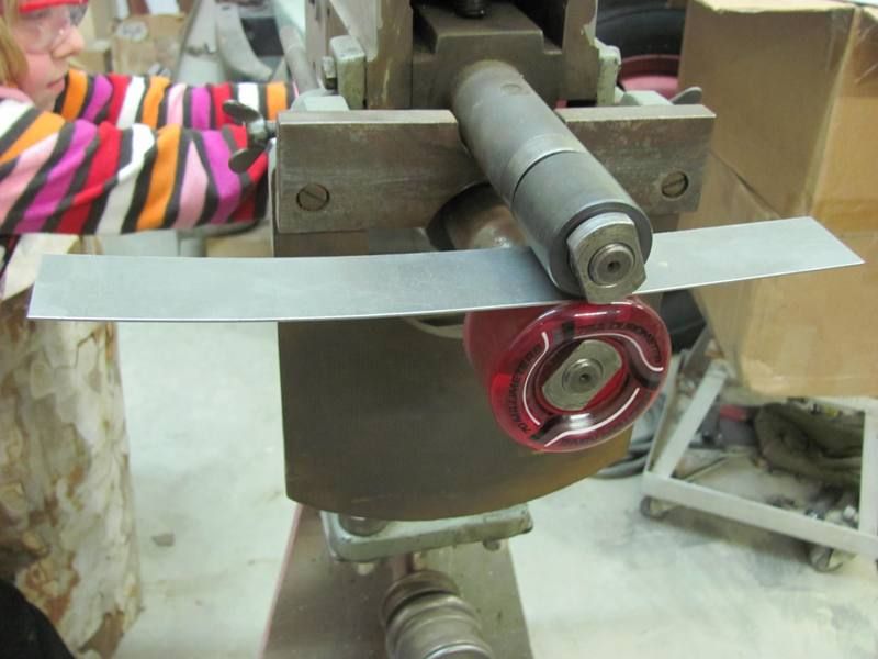
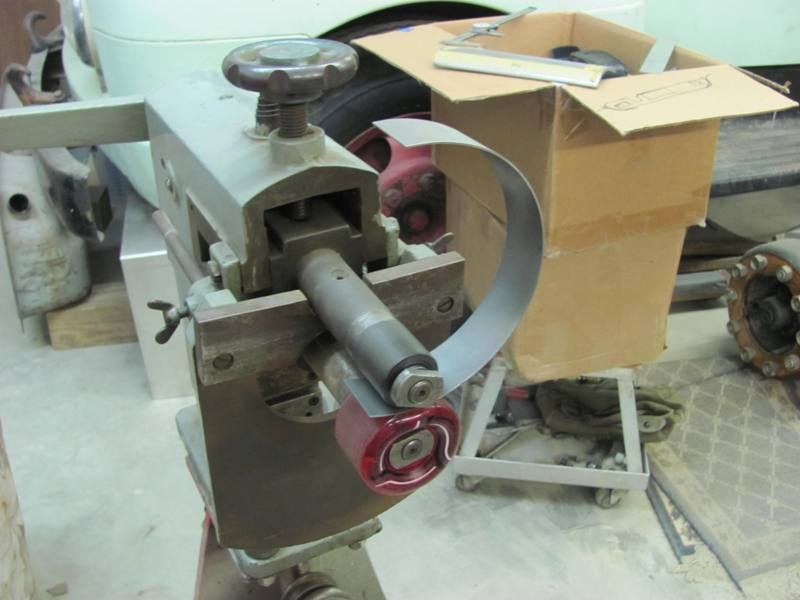
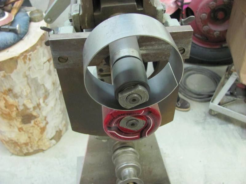
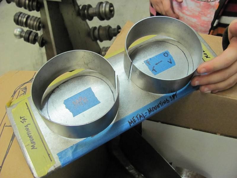
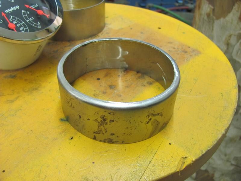
Not having a slip roll, I decided to try these in the bead roller:
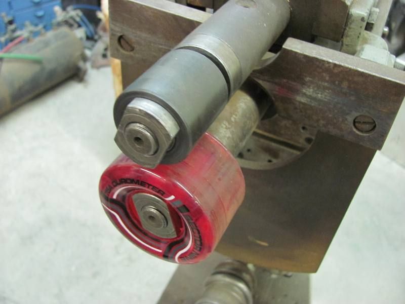
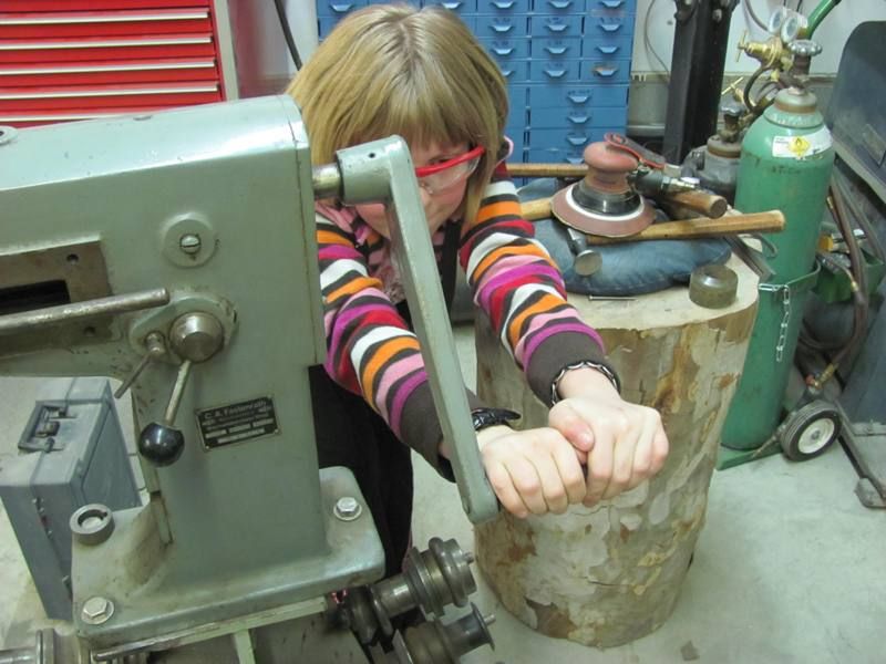
I had some help in the shop this evening, so in addition to having the powered option on the bead roller this evening, given the diameter of the gauge bezel, I was able to show her real world application of Pi X D....
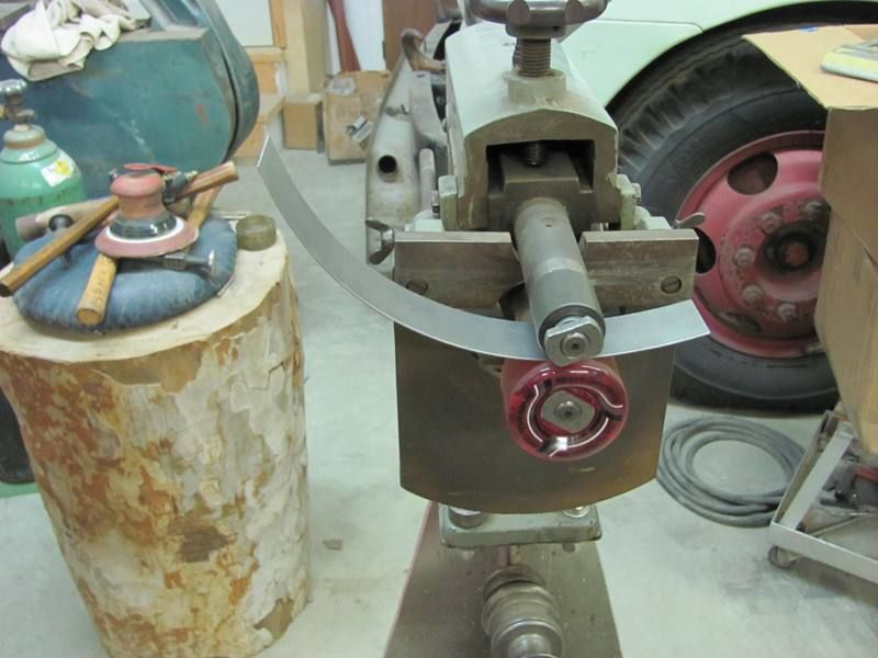
Just to test fit, here's the gauge with bracket, and the ring placed over both....
Both rings formed, tomorrow we'll get them welded up and tip some flanges for the bracket to push against...
Here's the new gauge with the clamping bracket....
Not having a slip roll, I decided to try these in the bead roller:
I had some help in the shop this evening, so in addition to having the powered option on the bead roller this evening, given the diameter of the gauge bezel, I was able to show her real world application of Pi X D....
Just to test fit, here's the gauge with bracket, and the ring placed over both....
Both rings formed, tomorrow we'll get them welded up and tip some flanges for the bracket to push against...
Last edited:
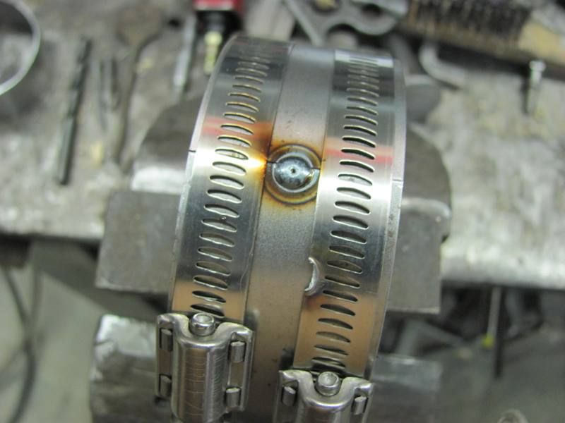
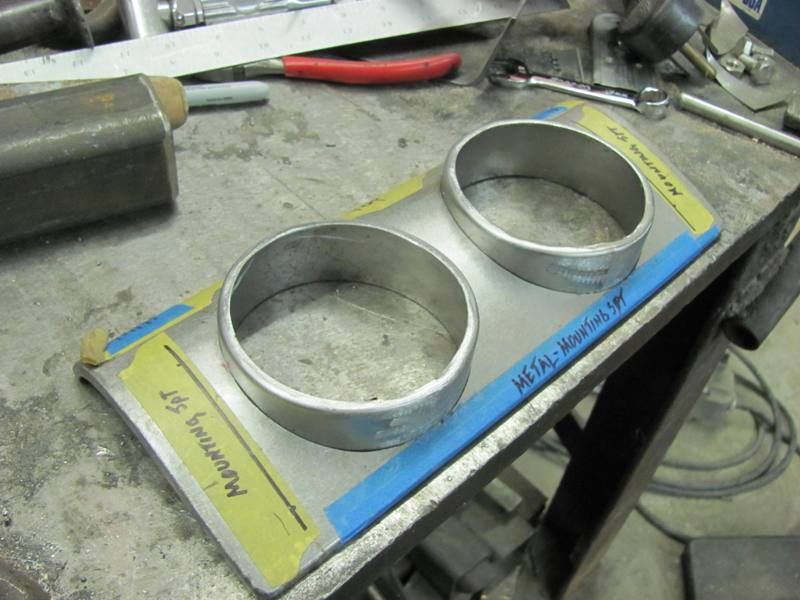
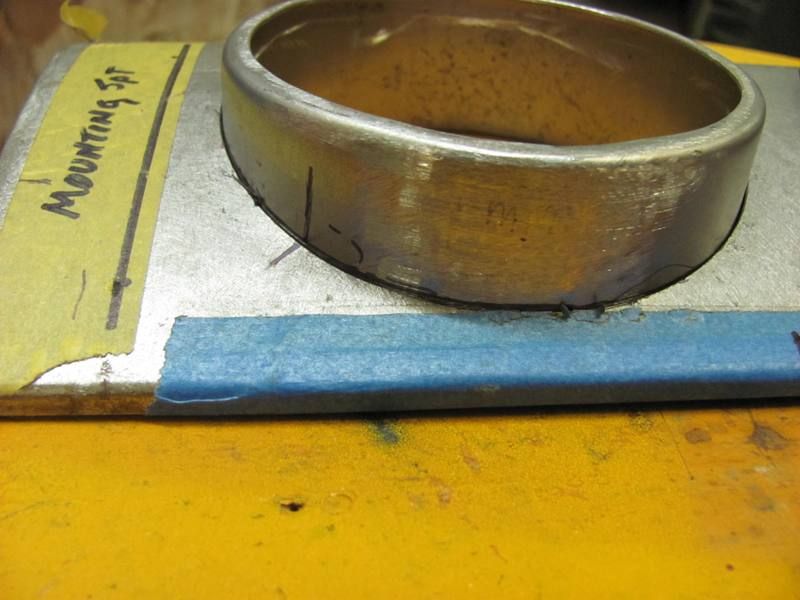
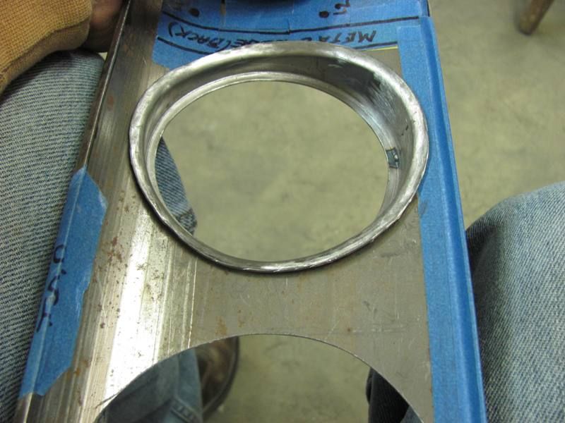
Thanks for the comments. Worked on the gauge panel again today, got the rings welded up...
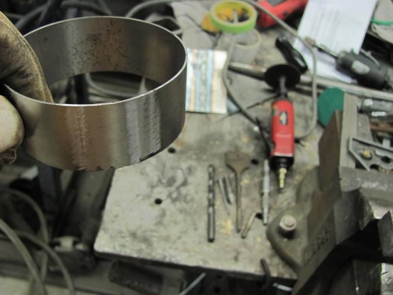
Then to tip a flange to hold the gauge in place, used these in the bead roller....
Applied a bit of pressure and started tipping the ring gradually as we went....
After getting the initial flange tipped to almost 45 degrees, the body hammer was used to get the flange to 90.
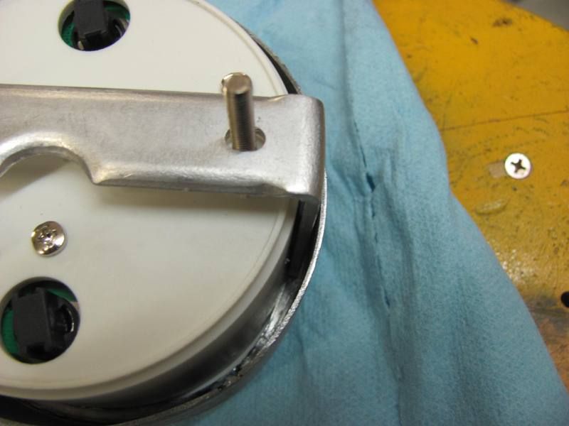
Fitted, and shown with the gauge's mouting bracket in place.....
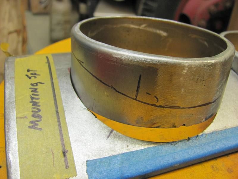
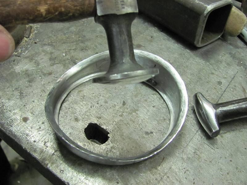
Now to fit the rings to the panel....
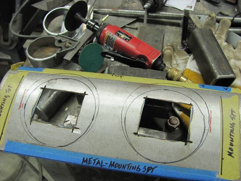
....and fine tuned with a drum sander.. A view in the panel....
Rather than weld around the perimeter of the hole, which will surely warp things up nicely, I'll tip a flange on the underside of the rings and spot weld to the panel.
Then to tip a flange to hold the gauge in place, used these in the bead roller....
Applied a bit of pressure and started tipping the ring gradually as we went....
After getting the initial flange tipped to almost 45 degrees, the body hammer was used to get the flange to 90.
Fitted, and shown with the gauge's mouting bracket in place.....
Now to fit the rings to the panel....
....and fine tuned with a drum sander.. A view in the panel....
Rather than weld around the perimeter of the hole, which will surely warp things up nicely, I'll tip a flange on the underside of the rings and spot weld to the panel.
Kevin54
MEMBER EMERITUS
Those look great!!! What will you do around the area where the ring is going through the dash portion to fill the small gap? Will you finish it off with something like some sort of filler or just let it go like it is? In actuality it may not show up like it does in the thread.
Kevin54
MEMBER EMERITUS
Kevin, I'm going to tip an outward flange on the back side of the panel, so I'll take a look at it then. If needed, once spot welded, will likely add a bit of 416 Evercoat around the perimeter...
So when you do that, what do you do? Mark a line around the contour of the dash panel and follow the line with the bead roller? Also in doing that (if that's the way) does it take two people to do it? I'm envisioning someone cranking the handle slow while you try to follow the line.
Then again, I may be off base as far as can be.
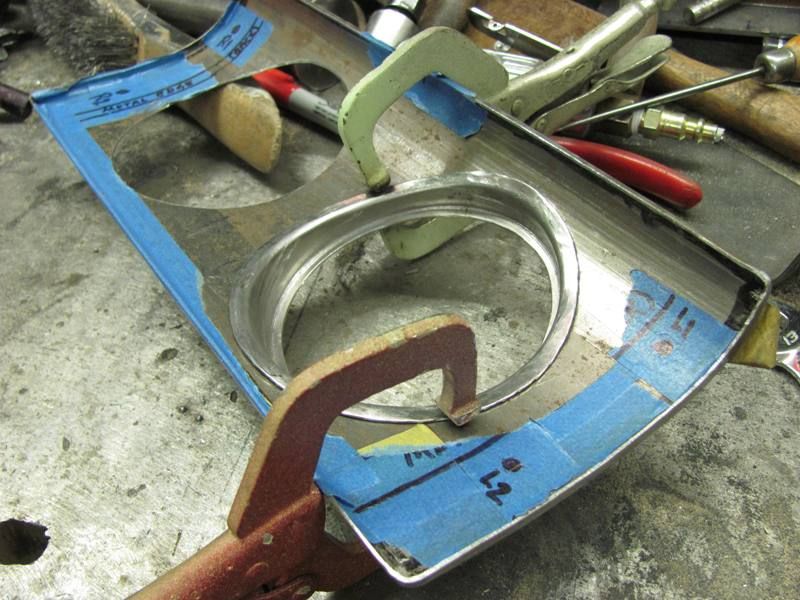
This is just what's going through my mind.Kevin, I was going to write a response, but thought....how long can it take to do one? So here's the pictures instead!
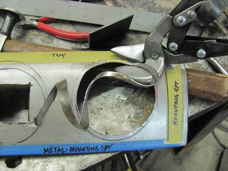
Before marking anything, the panel and both rings were pushed flat to the "table" surface. Then alignment marks added to keep us in the right location....
Marked along the surface of the panel against both rings..
Did an offset line 3/8" away and trimmed. This looked too wide to tip, so I went back and marked again at 3/16".
.....and trimmed again to the 3/16 mark. Changed to a different lower die for tipping this time.... made a complete revolution to "mark" the bend line and then started tipping...
Again went to about a 45 degree tip, placed the ring in the panel to see what needed more tipping....
Tipping along a wavy line does pose some "pulling" issues, so I did have some planishing/stretching to do in some areas. It's real close, but I have some tweaking left to do, and then I'll tackle the second one.
97dynaglide
Well-known member
Incredible work Robert. 
I'm enjoying this thread.
I'm enjoying this thread.
Omphaloskeptic
Well-known member
Robert, just dove into this thread today and I'll echo the others who applaud you skills. Wow, just incredible to see the steps used to convince sheet metal to 'bend to your will'. Every detail of your work is being studied by all of us 'wannabes', so we can have an inkling of the way work should be done as a true craftsman does it. As a neophyte when it comes to Bondo-free bodywork, I have a ton of questions, but I imagine a lot of answers come with 'trial and error'. A number of questions come to my mind as I read your posts:
1) When planishing a spot weld, how do you tell when you are using too much/not enough hammer force? I'm pretty sure it depends on the gauge, the filler used, dolly back pressure and the direction of the wind (lol), but are there any telltales on the spot weld itself that tells you the hammer blows need more/less force?
2) You specified what filler rod you are using (ER70S-7 wire), but what MIG settings do you like to use for these spot shots? Again, this probably depends on the vintage metal guage you are working with; I'm just wondering if there are any rules of thumb for this. Maybe the filler spool specifies machine settings; I just don't know.
3) When you were laying out for the cuts into the curved dash piece for the gage 'barrels', how did you 'extend' the shape of the hole onto the curved dash piece where you could not touch the 'barrel' to the dash metal?
4) It seems your hole cuts came out spot on; how did you align both 'barrels' relative to each other so they both pierce the curved dash piece at the same angle?
I could probably continue to demonstrate my 'sheet metal ignorance' by asking more questions, but I'll be most content if you can take a moment to 'edgeumacate' this mere mortal.
Responses in Blue......
Robert, just dove into this thread today and I'll echo the others who applaud you skills. Wow, just incredible to see the steps used to convince sheet metal to 'bend to your will'. Every detail of your work is being studied by all of us 'wannabes', so we can have an inkling of the way work should be done as a true craftsman does it. As a neophyte when it comes to Bondo-free bodywork, I have a ton of questions, but I imagine a lot of answers come with 'trial and error'. A number of questions come to my mind as I read your posts:
1) When planishing a spot weld, how do you tell when you are using too much/not enough hammer force? I'm pretty sure it depends on the gauge, the filler used, dolly back pressure and the direction of the wind (lol), but are there any telltales on the spot weld itself that tells you the hammer blows need more/less force?
Typically the panel will be a tight fit unless I made a mis-cut, so when planishing one weld dot I will watch the panel paying close attention to this tight joint. If it is seen to start spreading, then I went just a bit too far. So this "test" on the first weld kinda sets the bar for the rest as to how much is needed, backing off slightly as needed. This is primarily to keep the shrinking effects in check and any panel inconsistencies can be addressed with final planishing at the end...
2) You specified what filler rod you are using (ER70S-7 wire), but what MIG settings do you like to use for these spot shots? Again, this probably depends on the vintage metal guage you are working with; I'm just wondering if there are any rules of thumb for this. Maybe the filler spool specifies machine settings; I just don't know.
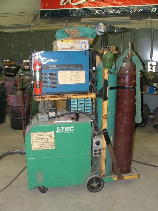
My welder is an L-Tec migmaster 250, which is the predecessor to Esab. (tells you how old it is
This was close enough to the adjacent bend detail that it held most of the weld shrinking issues in check, so I waited until after all welding complete to planish the welds...
But the settings on my machine will likely not apply to what you have. So if you are performing similar methods in your welding, I would recommend following your machine's recommendations for 16 ga metal (if welding 19 or 18 ga panels) and do some test welds. If you don't get full weld penetration in the one dot, then go the next higher heat. If it's blowing holes, more wire feed speed. I will add that most use .023 or .030 wire on sheet metal, but for whatever reason my machine and the setup I'm using seem to do better with .035 wire. But as pricey as wire is, I would say to try adjustment changes first (cheaper) before allowing anyone to talk you into changing wire size because it's what they are using in a different machine... That's the method to my madness, hope it helps.
My Mig welder is here on the bottom, the Miller Econotig has been replaced...
3) When you were laying out for the cuts into the curved dash piece for the gage 'barrels', how did you 'extend' the shape of the hole onto the curved dash piece where you could not touch the 'barrel' to the dash metal?
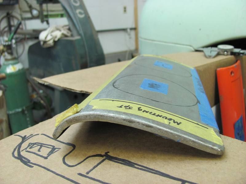
The red sharpie mark gave me a starting point along the sides, and the tape at the bottom was cut a consistent width from the bottom. These were my alignment marks to place the rings, and just rolled it up, marking the inside of the ring. This gave me an undersized hole that was finalized using a 1-1/2" diameter drum sander..
4) It seems your hole cuts came out spot on; how did you align both 'barrels' relative to each other so they both pierce the curved dash piece at the same angle?
The rings are not yet attached, for that picture they were merely sitting in the hole. Before marking the outside of the rings for trimming the bottom for the flange on the backside, all pieces were pushed flat against the table for a consistent starting point. Still have one left to do, so we'll see how well that plan works out...
I could probably continue to demonstrate my 'sheet metal ignorance' by asking more questions, but I'll be most content if you can take a moment to 'edgeumacate' this mere mortal.
Ask away...having to explain something makes me understand it better myself..
Last edited: