
You are using an out of date browser. It may not display this or other websites correctly.
You should upgrade or use an alternative browser.
You should upgrade or use an alternative browser.
MP&C Shop Projects
- Thread starter MP&C
- Start date


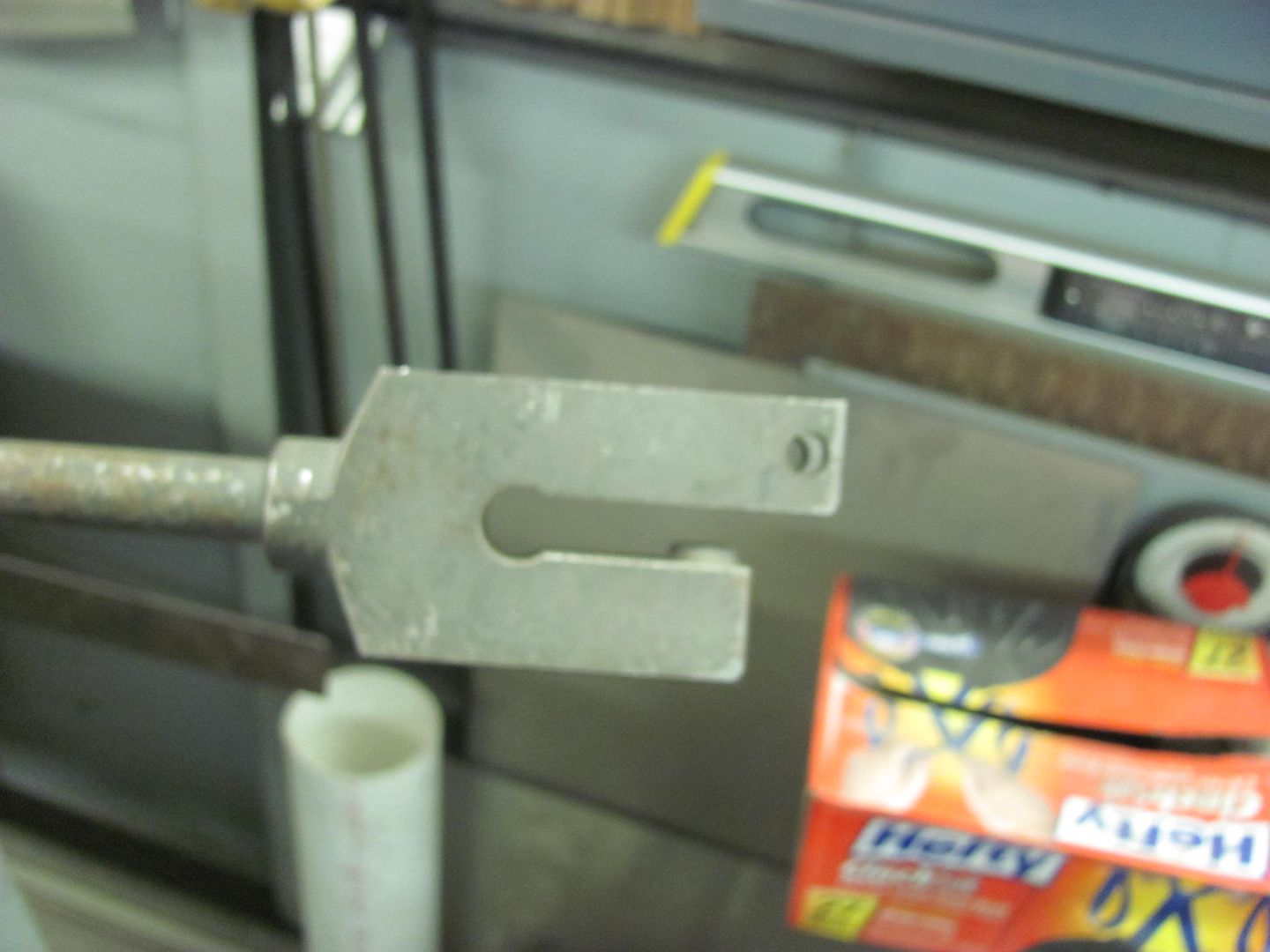
The vise on the left was given to me by my brother in law, the one on the right was an auction find that I couldn't pass up. Having the two side by side came in handy when we were rebuilding the 55's rear lift gate.. Since then I've just been too busy to take the extra one off the table...
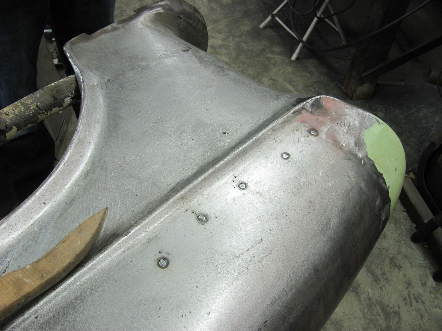
Tonight we worked on getting the front fenders ready for epoxy primer, just a few more items to cross off the list. An earlier repair to resolve some rust on the top of the fenders.........
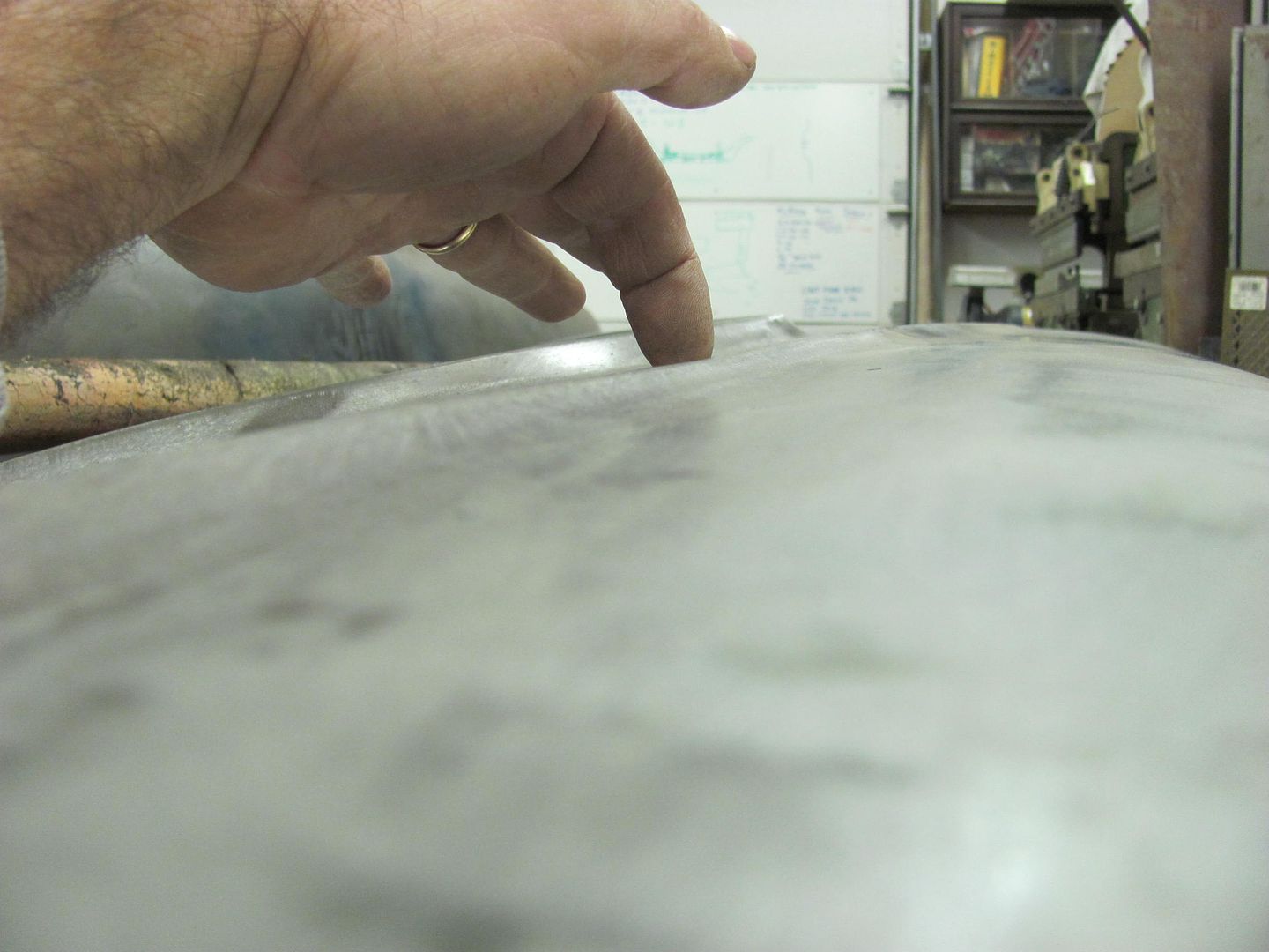
.........when checking the gap to the hood recently we noticed it was slightly wide at these spots where the weld had pulled. Shown here with the straight edge....
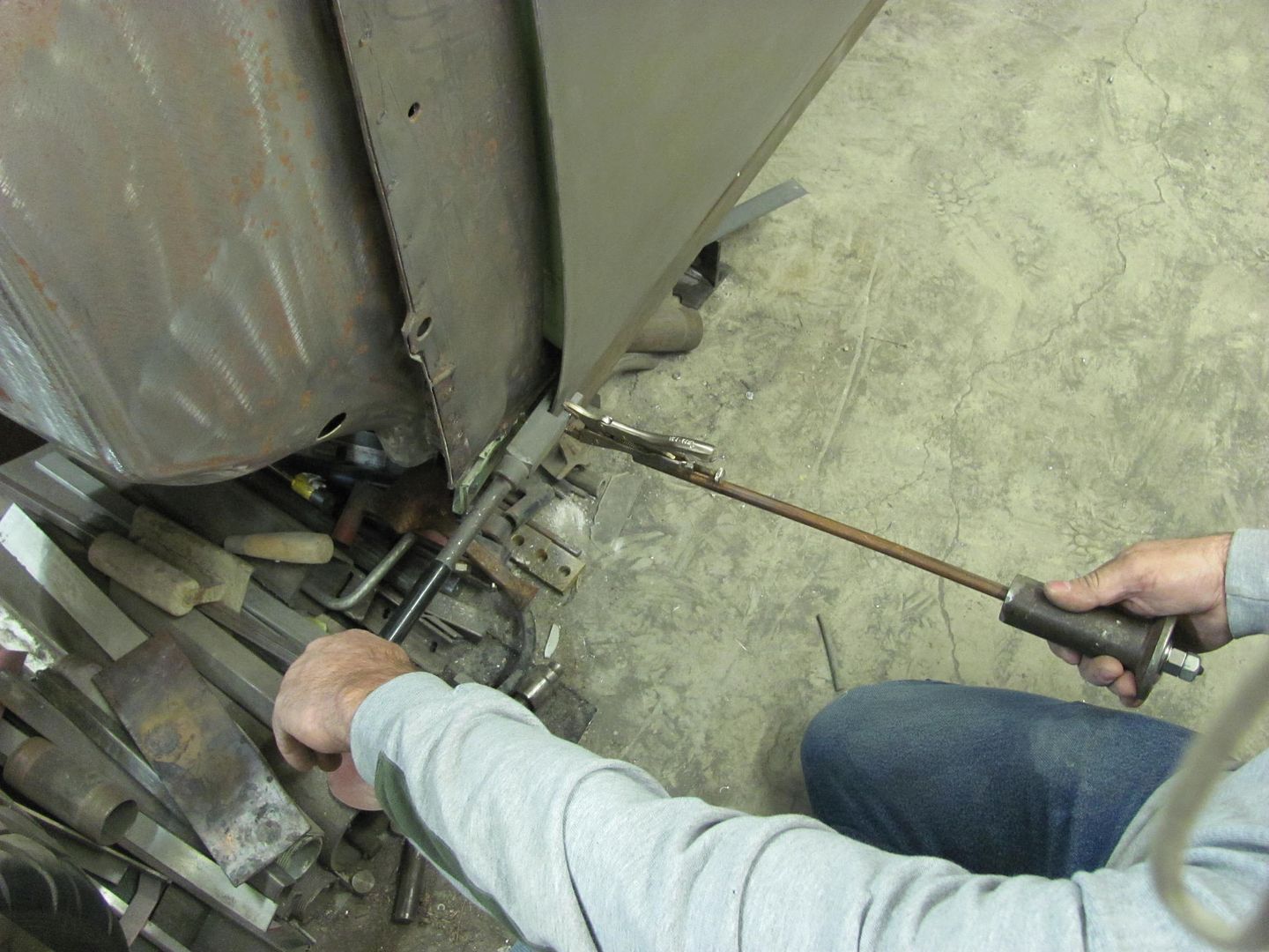
Time to make a tool that will reach between the inner fender brace for a bit of bumping...
The shortened hammer comes in handy again...
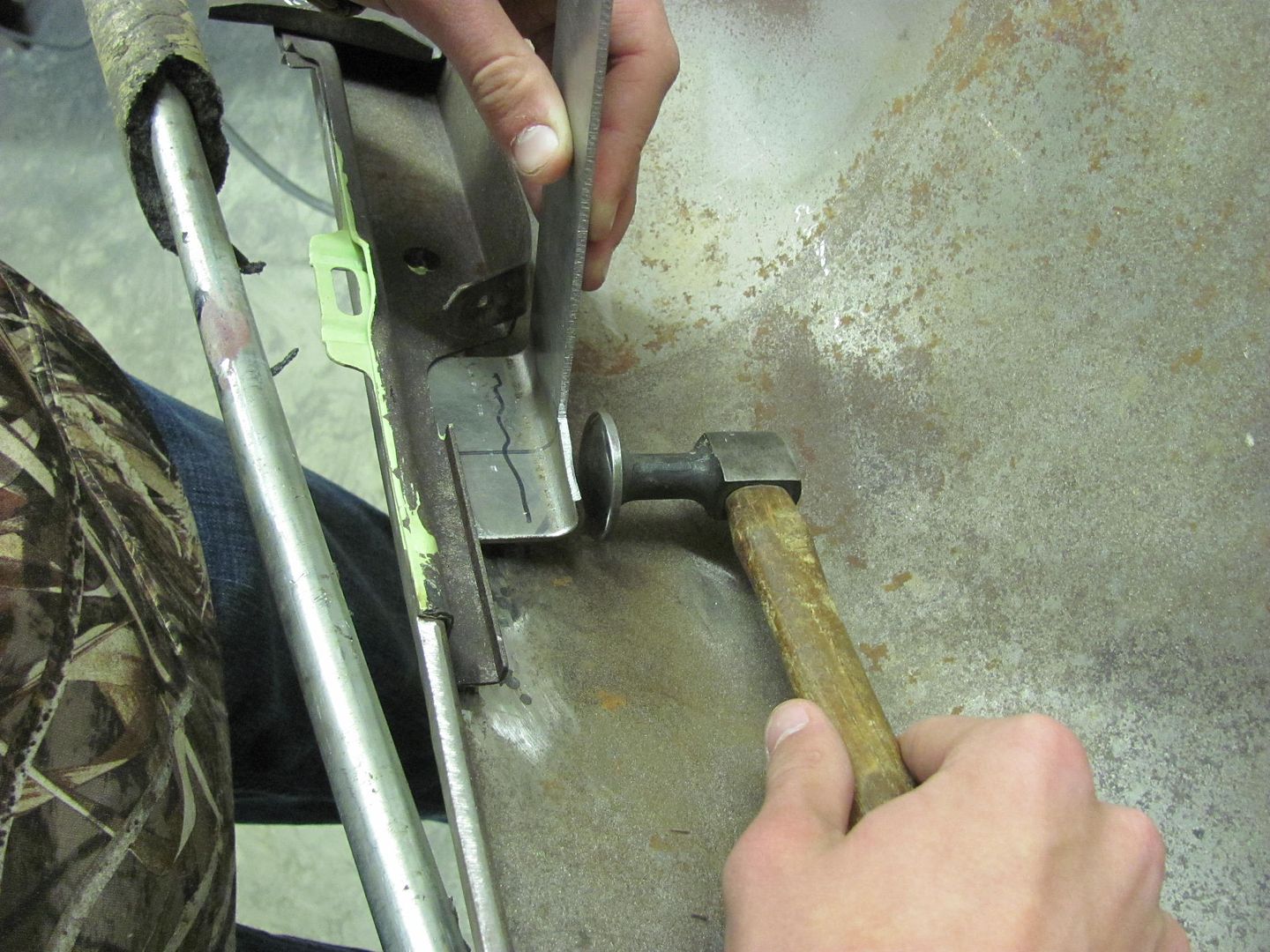
A few good raps along the area brought it out nicely.
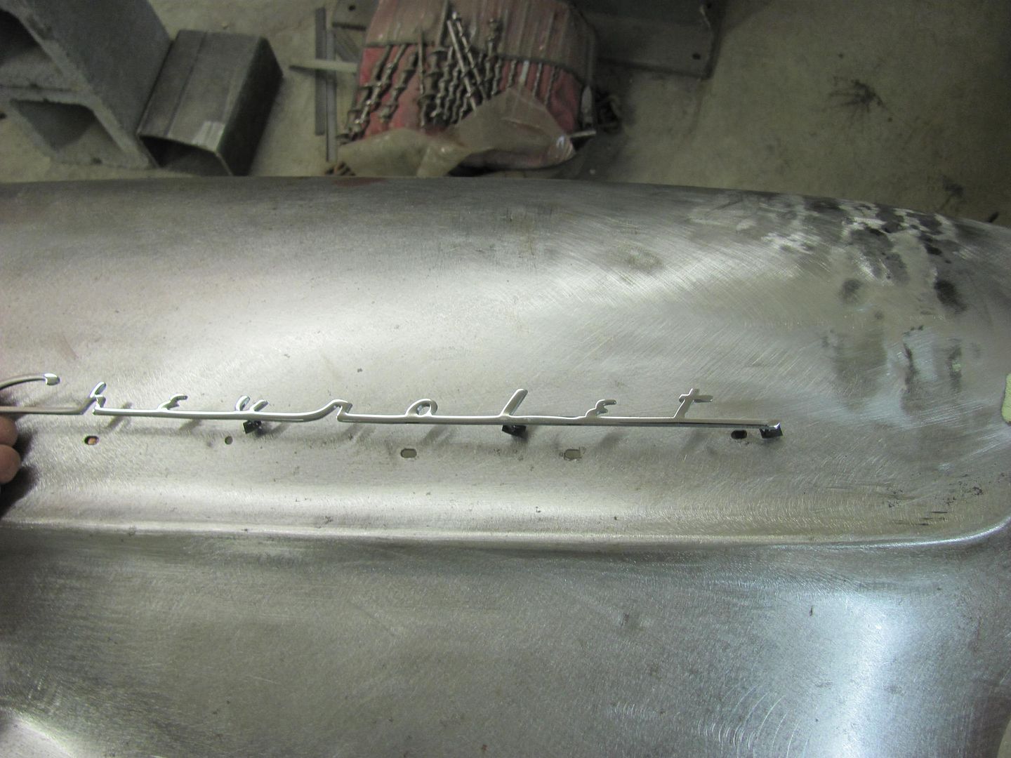
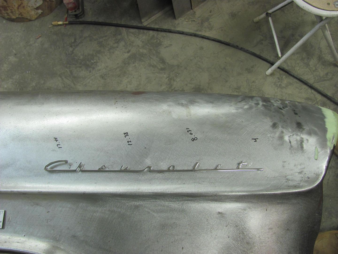
Next, we have some early model fender emblems to install on the front fenders, so we needed to fill the old holes...
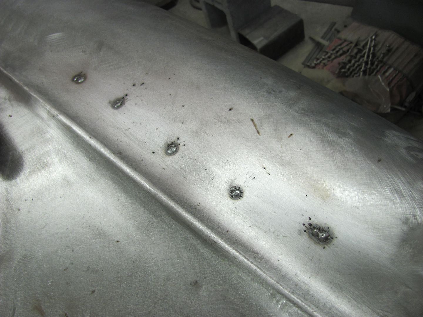
Three separate quick zaps were used (about a minute in between) to minimize the heat introduced into the panel for filling the slotted holes. Note minimal HAZ..
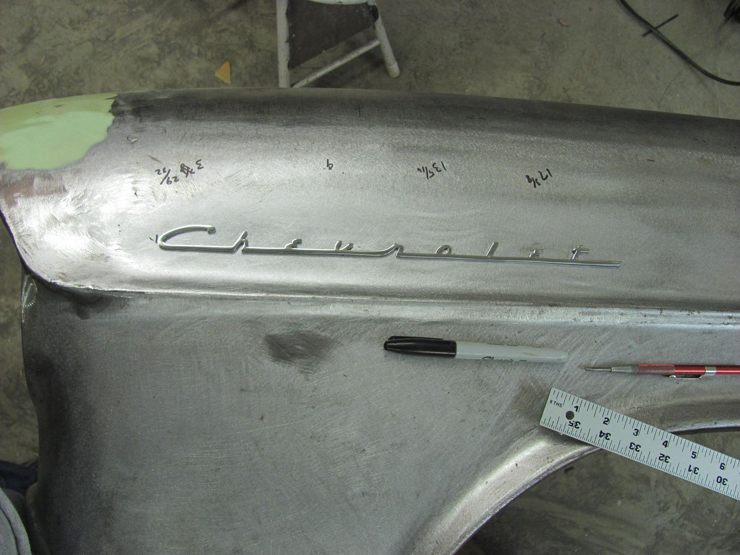
Holes laid out and drilled for the new emblem...
Other fender...
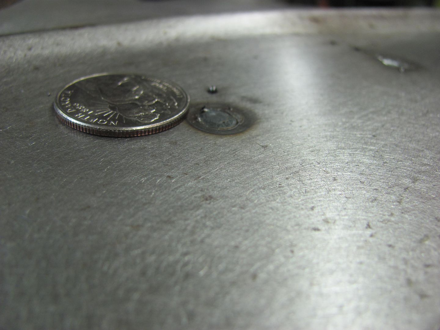
Note minimal weld bead height using EZ Grind, heat set for 14 ga...
Next, we had one more minor adjustment to do to the driver door lower corner. It was tweaked inward slightly and needed some adjustment. I recently noticed one of my hole punches was broken, and it looks like it will work for what we need, in conjunction with the vise grip dent puller...
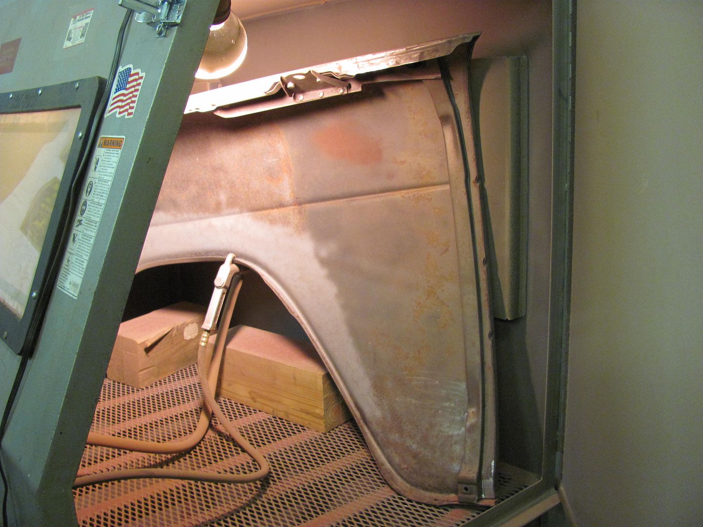
Kyle started media blasting the inside of the driver's fender.... A bit of a squeeze in a 58" wide blast cabinet..
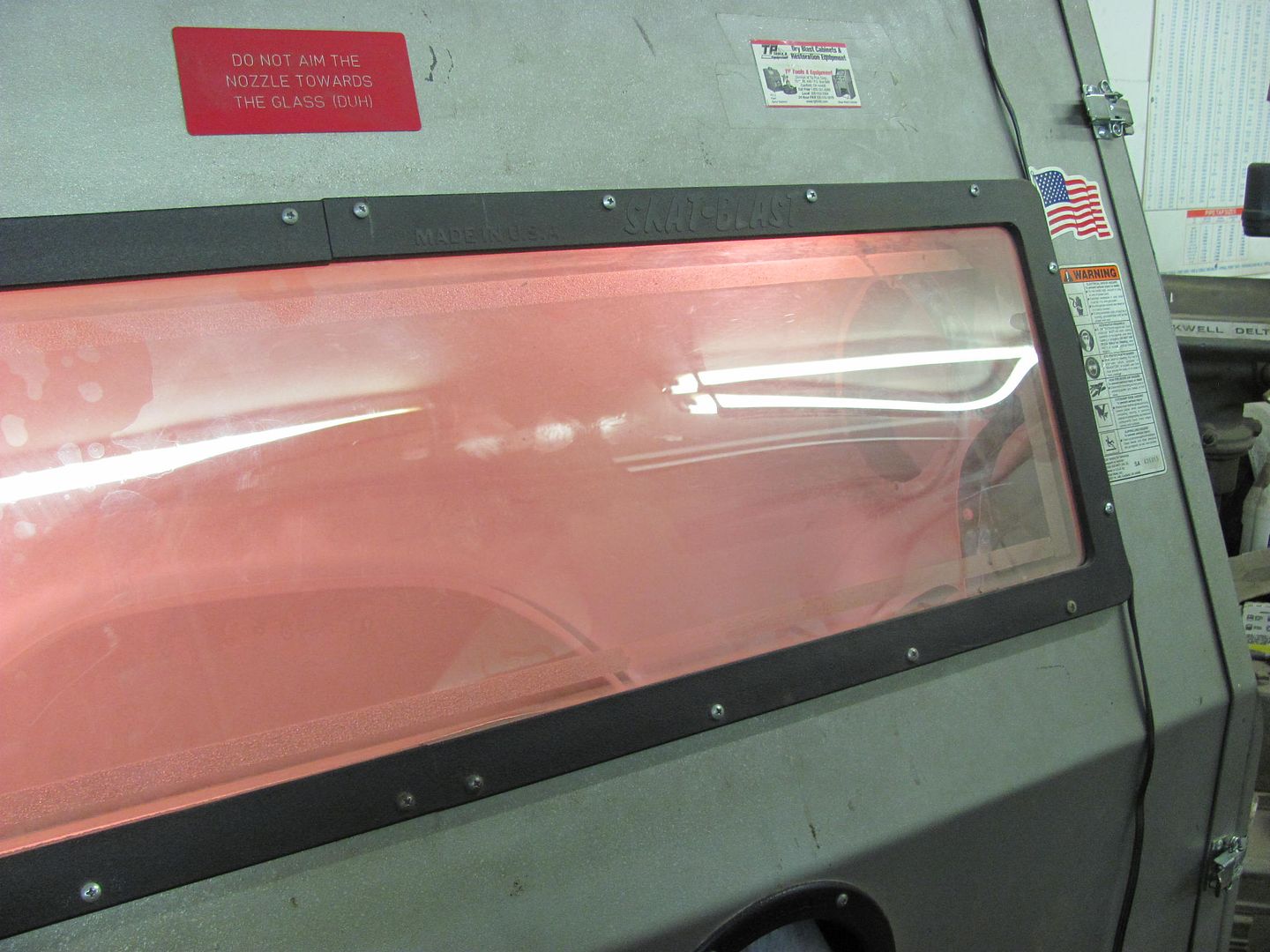
Rather tight to the door!

Until next time.....
.........when checking the gap to the hood recently we noticed it was slightly wide at these spots where the weld had pulled. Shown here with the straight edge....
Time to make a tool that will reach between the inner fender brace for a bit of bumping...
The shortened hammer comes in handy again...
A few good raps along the area brought it out nicely.
Next, we have some early model fender emblems to install on the front fenders, so we needed to fill the old holes...
Three separate quick zaps were used (about a minute in between) to minimize the heat introduced into the panel for filling the slotted holes. Note minimal HAZ..
Holes laid out and drilled for the new emblem...
Other fender...
Note minimal weld bead height using EZ Grind, heat set for 14 ga...
Next, we had one more minor adjustment to do to the driver door lower corner. It was tweaked inward slightly and needed some adjustment. I recently noticed one of my hole punches was broken, and it looks like it will work for what we need, in conjunction with the vise grip dent puller...
Kyle started media blasting the inside of the driver's fender.... A bit of a squeeze in a 58" wide blast cabinet..
Rather tight to the door!
Until next time.....
Last edited:
TimeWarpF100
Well-known member
Amazing stuff Robert, Simply Amazing stuff . . .
If you ever decide to get to a warmer climate I could use a few needed "lessons".
I do look for updates on your thread daily . .
If you ever decide to get to a warmer climate I could use a few needed "lessons".
I do look for updates on your thread daily . .
1971gsfan
Well-known member
^^^^^ Ditto what He said
Kevin54
MEMBER EMERITUS
Robert....when you filled in the holes for the emblems, do you not back the hole up with copper and if not, why not? Too much of a hassle?
Thanks for the comments guys.
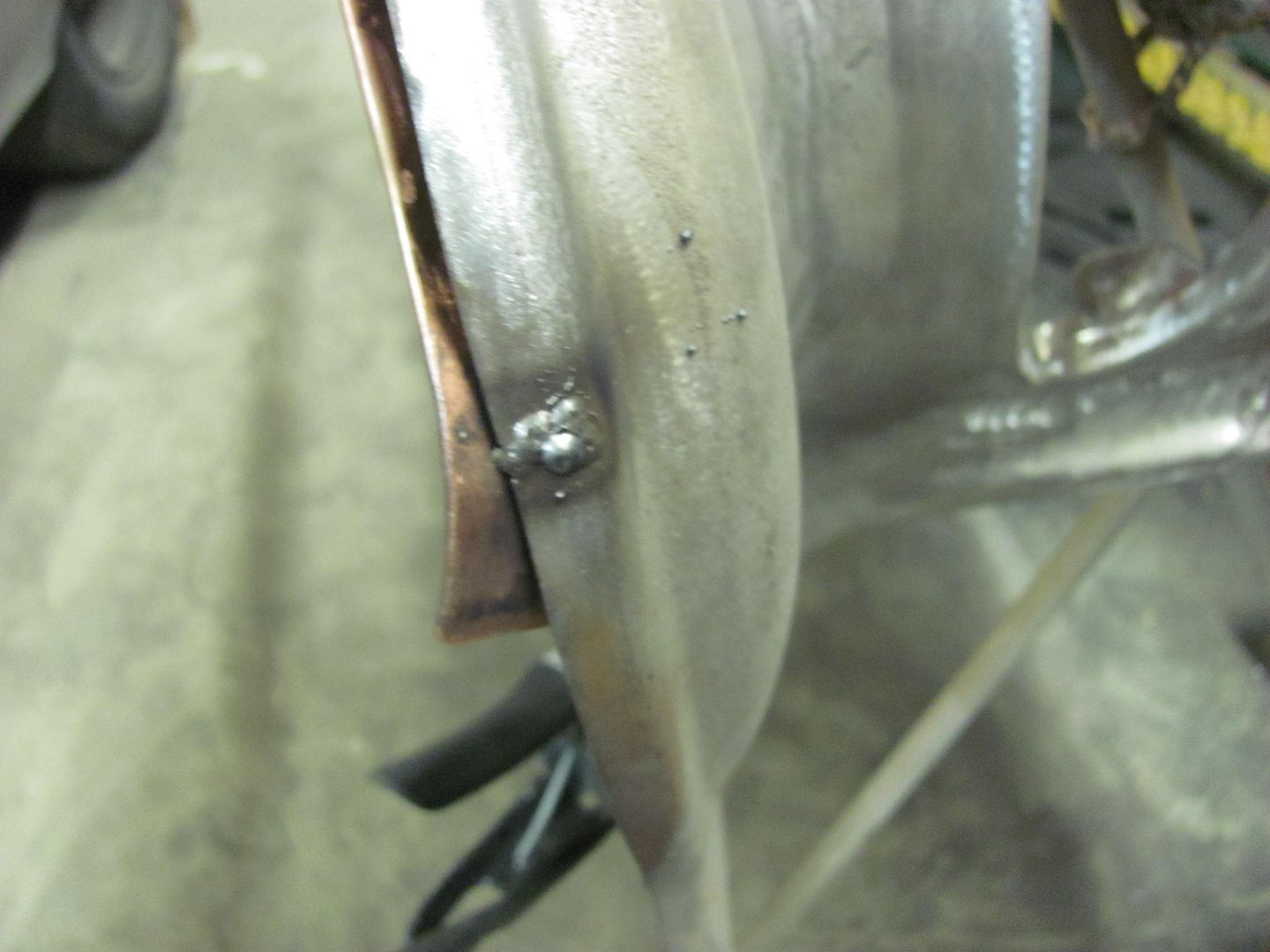
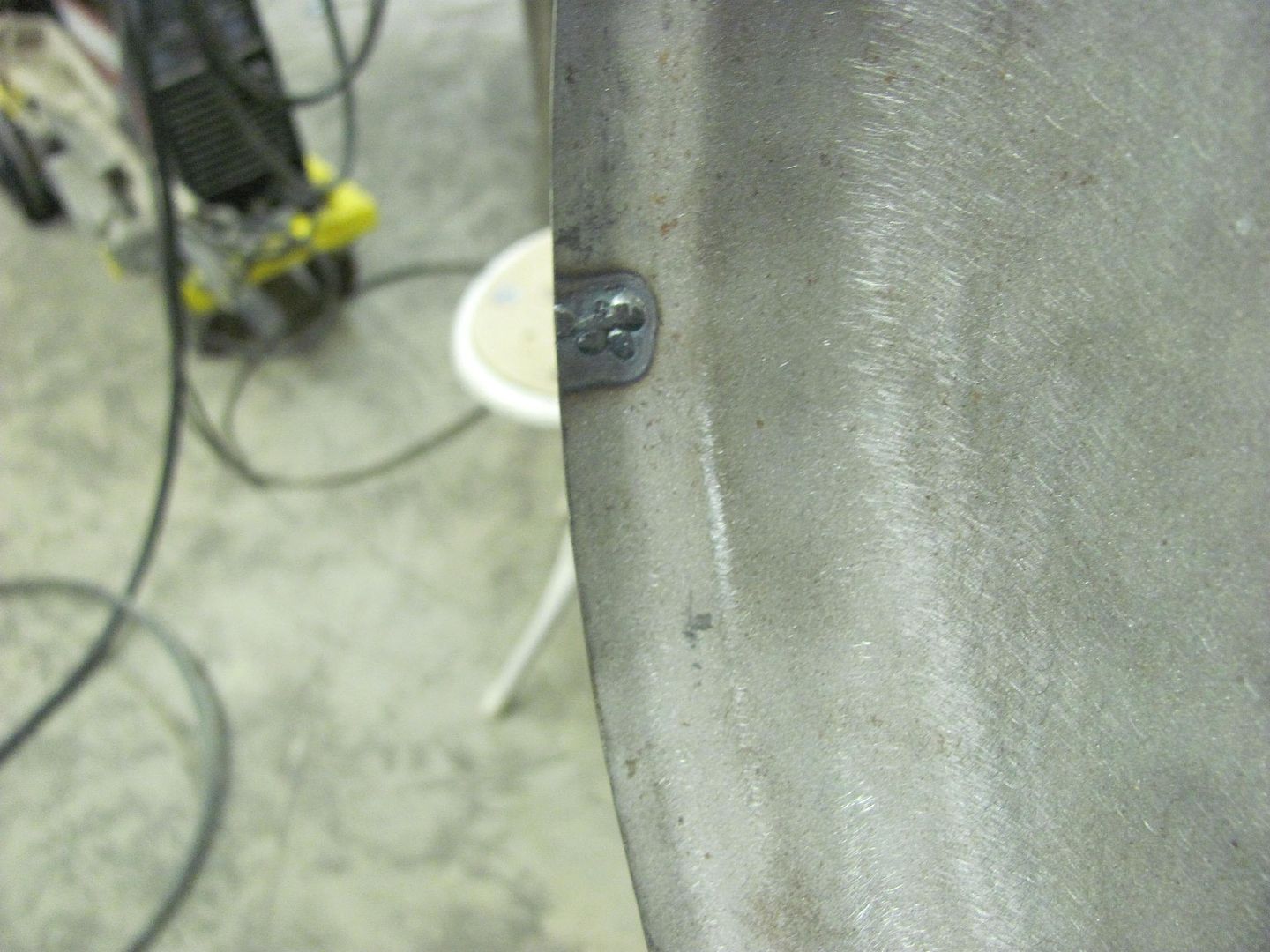
Kevin, the one hole is about 1/8 diameter, the slots are about 1/8 by 1/4. A bit smaller and I would have just welded them, any larger I would have likely made some sheet metal plugs. So to insure the holes didn't become any larger, I used a copper backer behind the holes..
If you look at the hole under the "h", you can see the copper behind the hole...
Robert....when you filled in the holes for the emblems, do you not back the hole up with copper and if not, why not? Too much of a hassle?
Kevin, the one hole is about 1/8 diameter, the slots are about 1/8 by 1/4. A bit smaller and I would have just welded them, any larger I would have likely made some sheet metal plugs. So to insure the holes didn't become any larger, I used a copper backer behind the holes..
If you look at the hole under the "h", you can see the copper behind the hole...
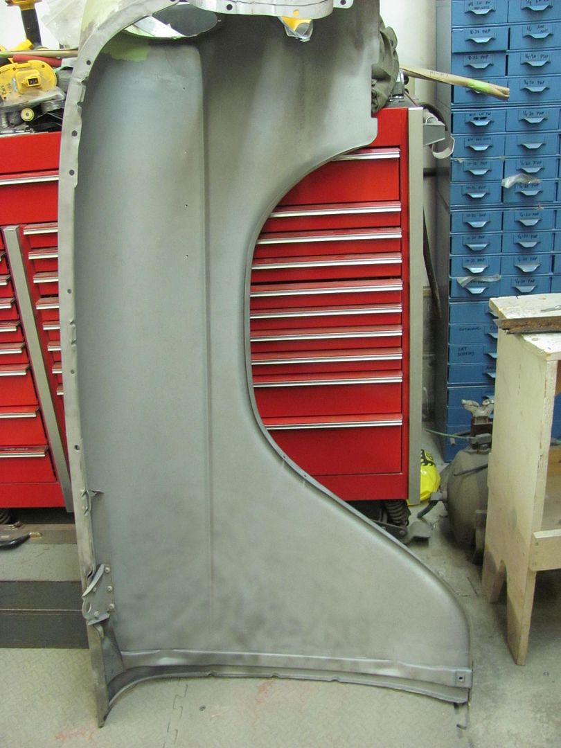
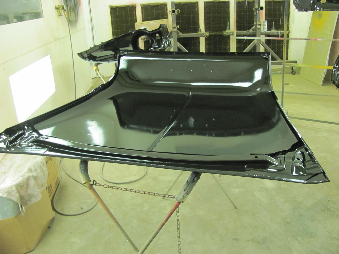
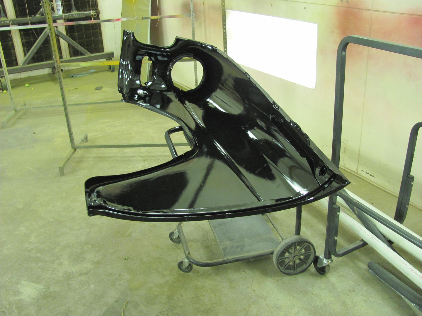
While I was doing the family thing today at an FLL robotics competition, Kyle worked some more on prepping the front fenders for priming..
One down......
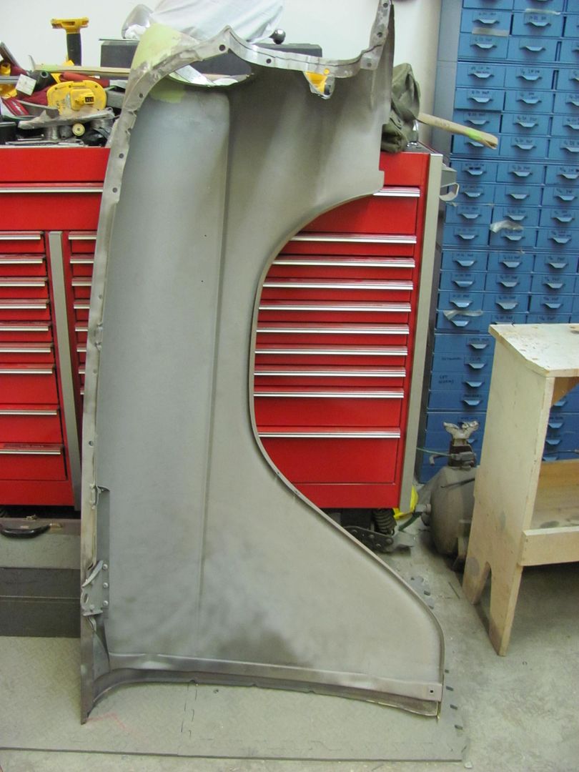
One to go....
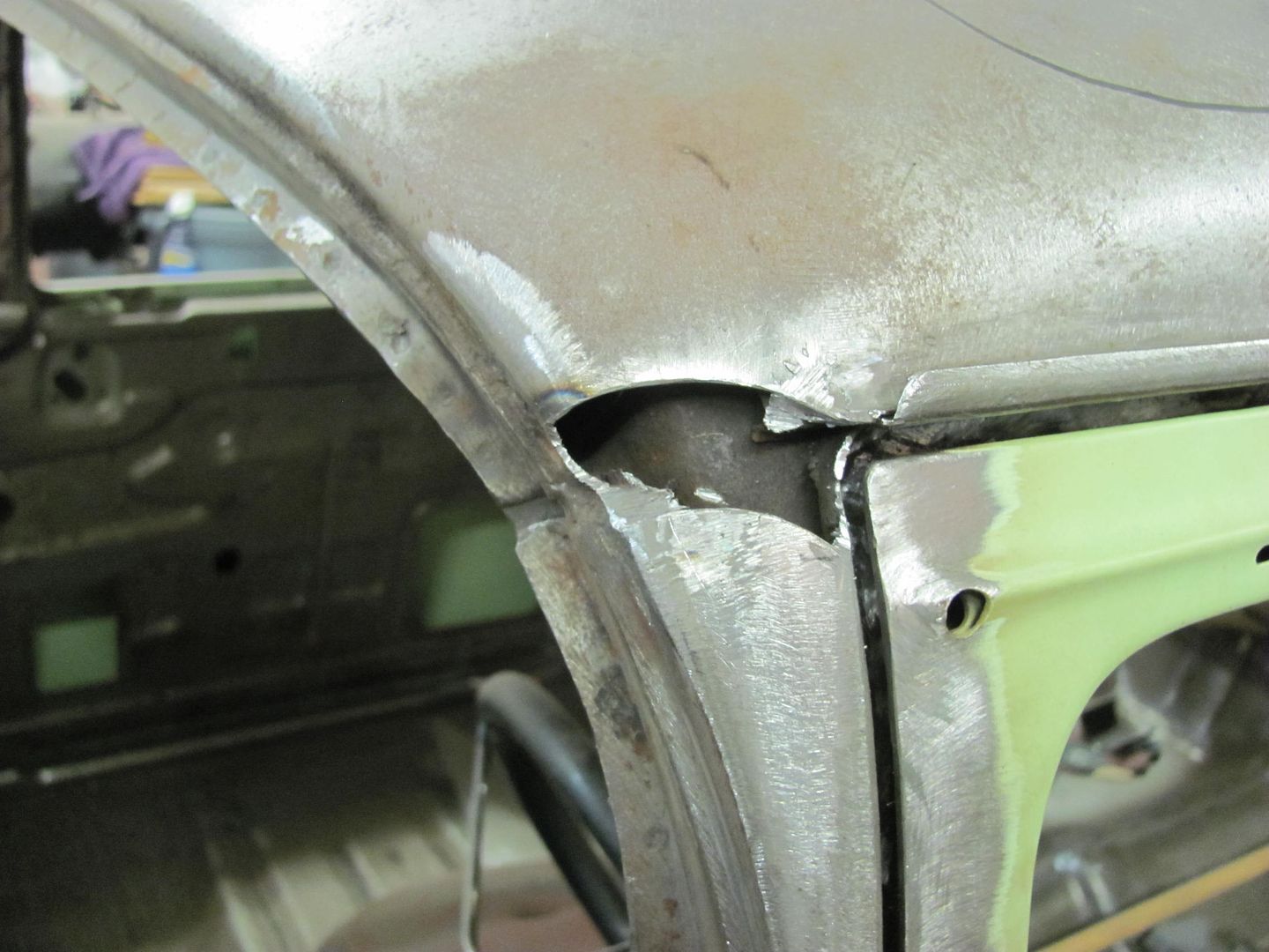
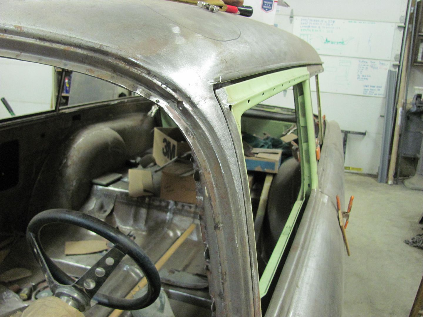
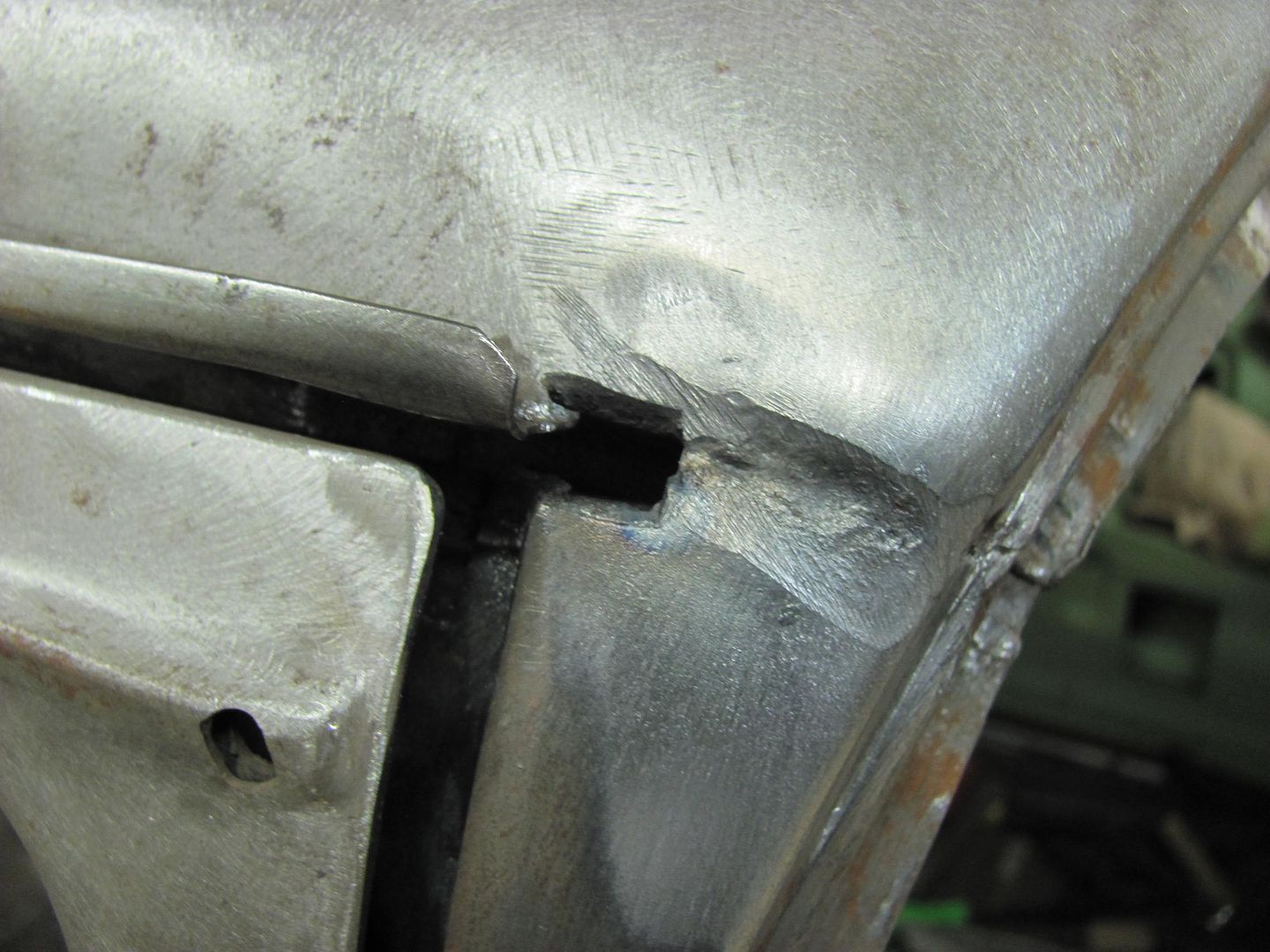
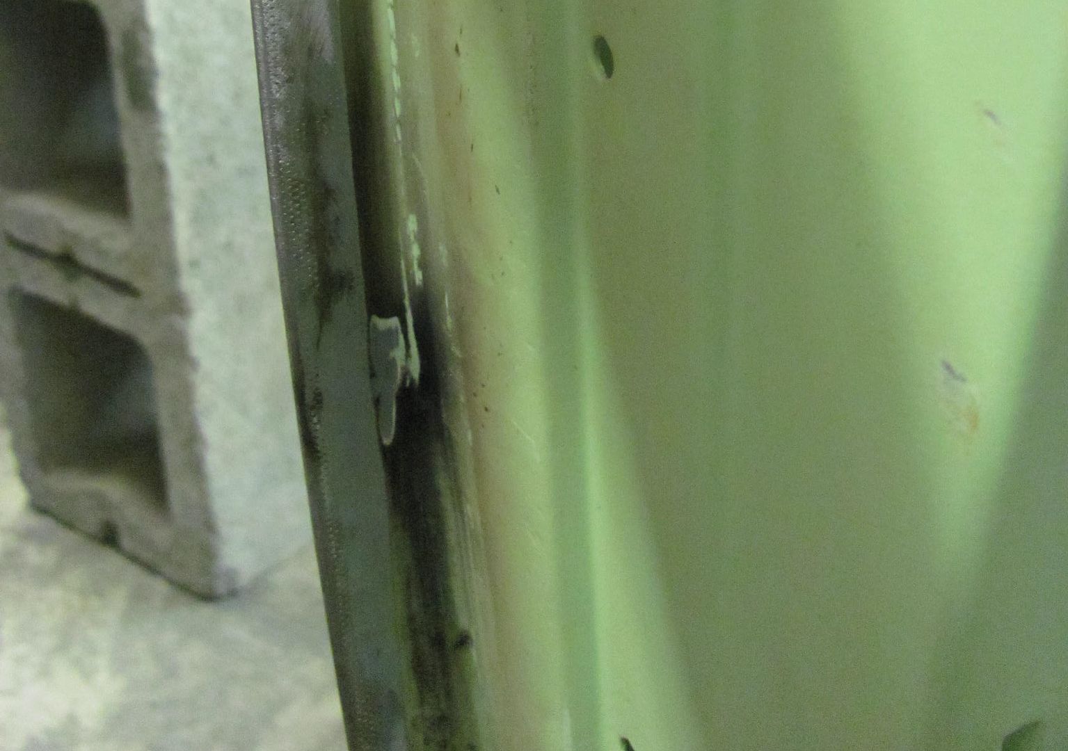
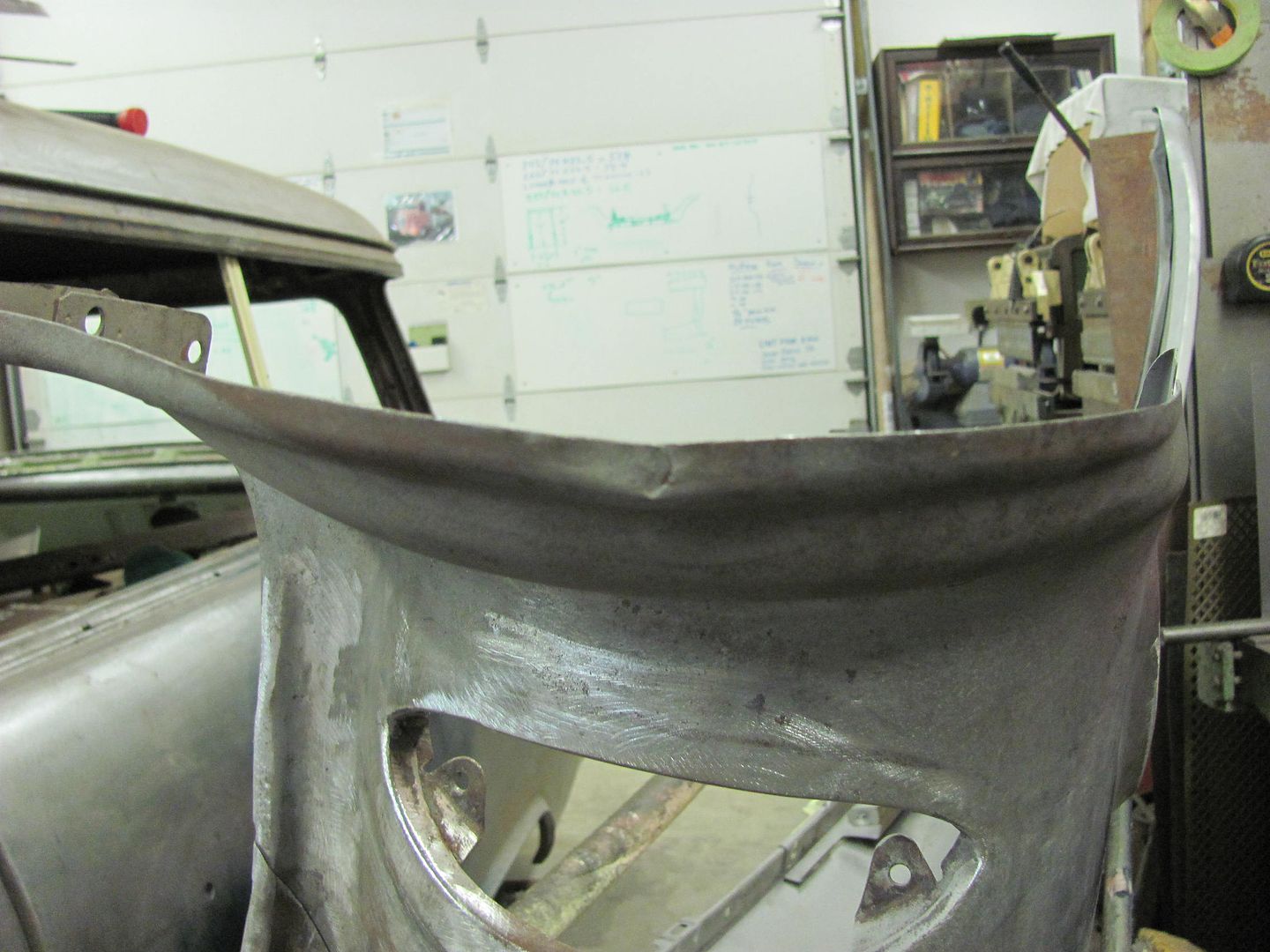
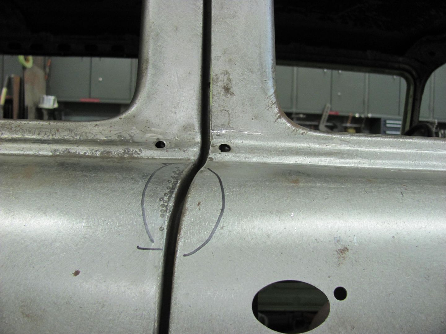
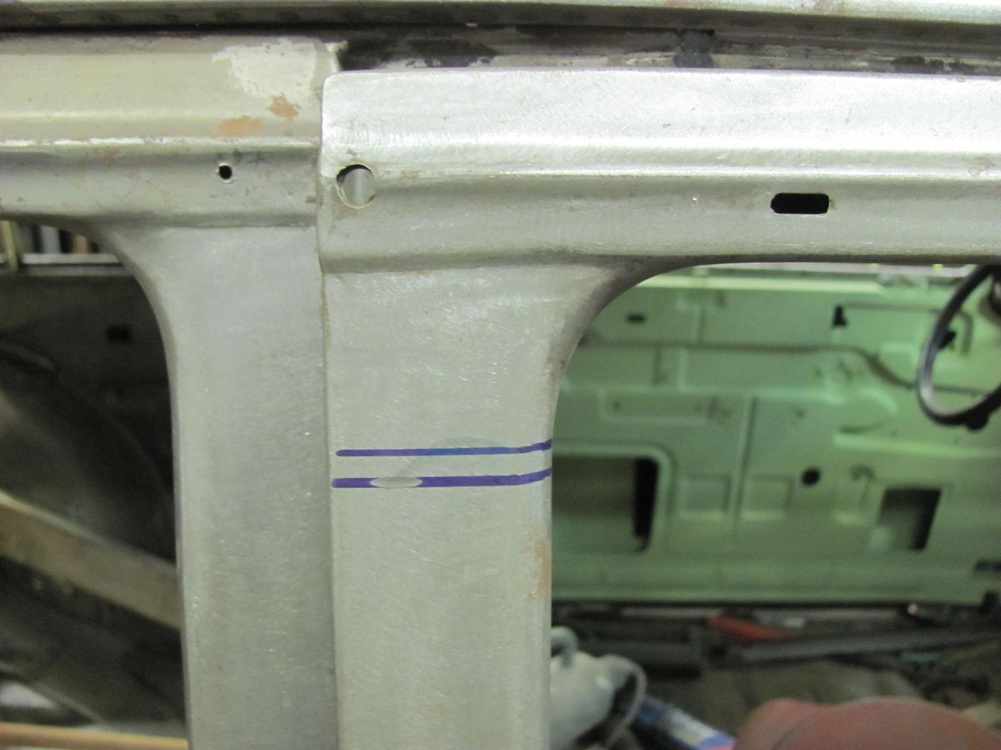
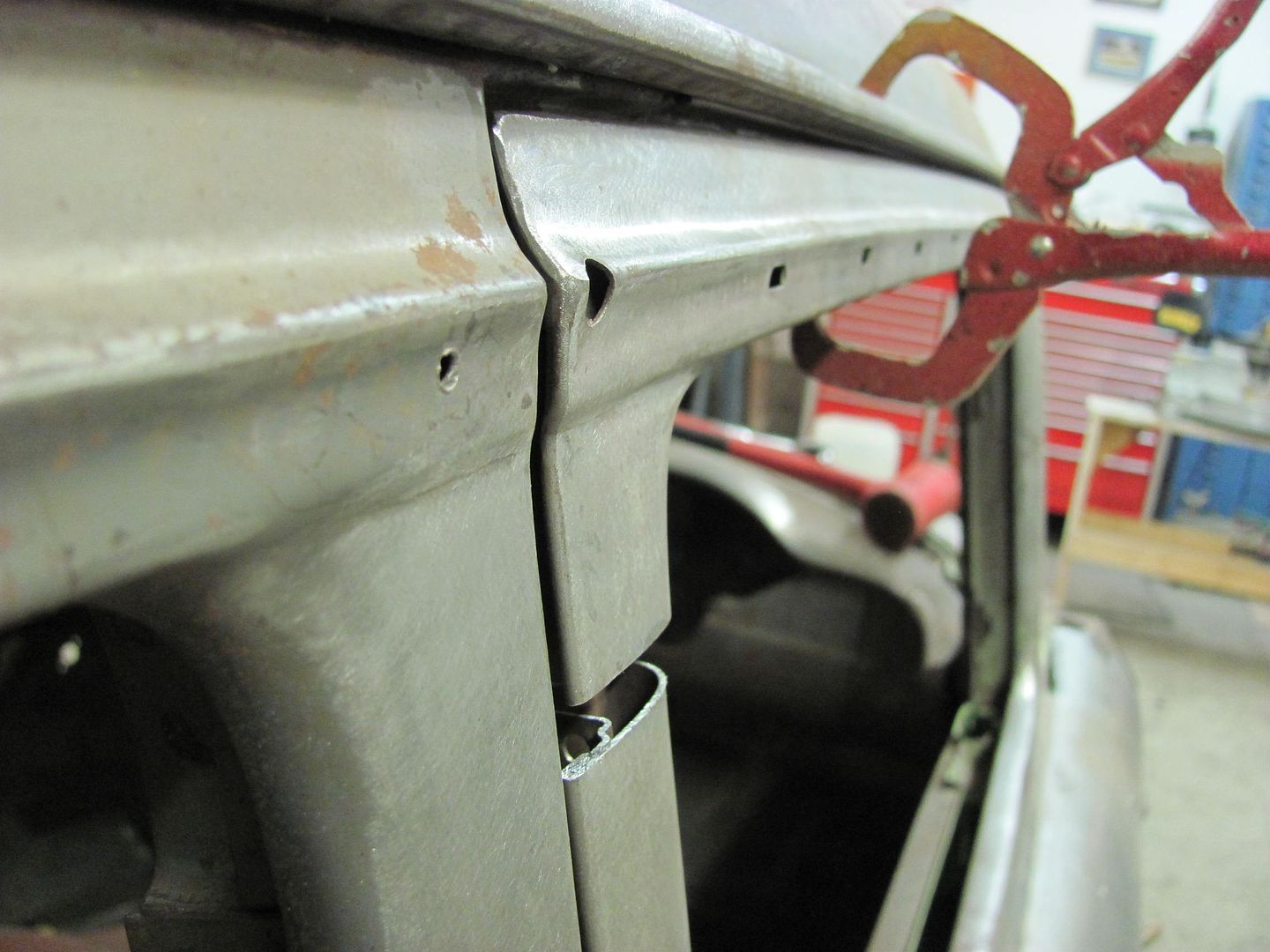
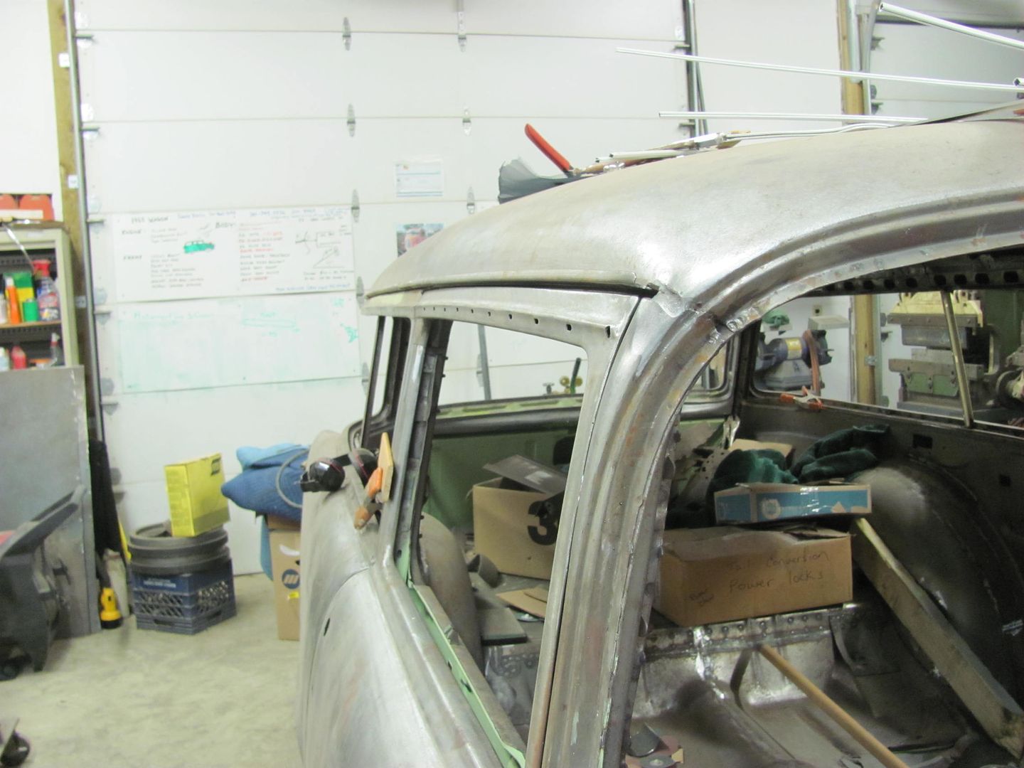
Another issue that plagues most of the trifive Chevrolets is cracking at the leaded joint at the top of the A pillar.
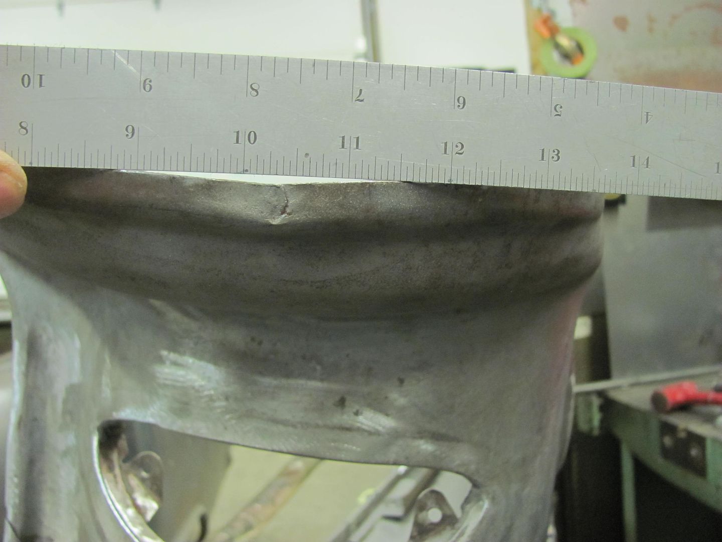
A look at the other side shows a gap that is quite a stretch to expect a good permanent repair regardless of the filler used..
At over 1/4" wide, something we will need to address...
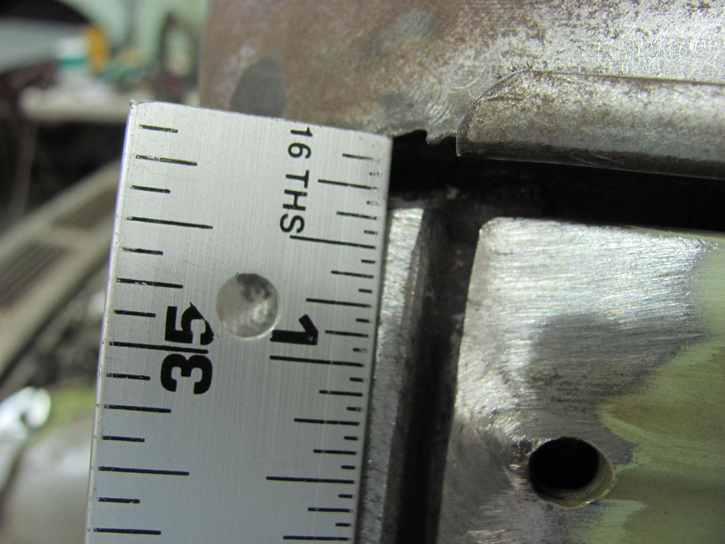
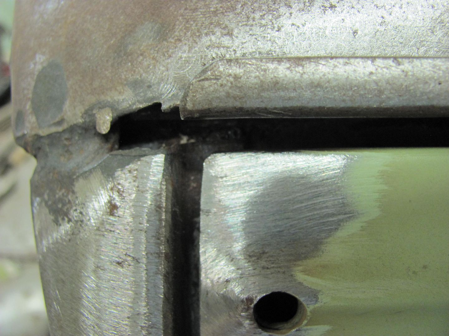
So we'll attempt a repair similar to the radius-ing that was done on the rear tailgate, using STEEL..
Until next time....
One down......
One to go....
Another issue that plagues most of the trifive Chevrolets is cracking at the leaded joint at the top of the A pillar.
A look at the other side shows a gap that is quite a stretch to expect a good permanent repair regardless of the filler used..
At over 1/4" wide, something we will need to address...
So we'll attempt a repair similar to the radius-ing that was done on the rear tailgate, using STEEL..
Until next time....
E12-535iTurbo
Well-known member
I'm curious what you think about this issue. The appearence of a gap there indicates that the body is actually deforming. Trying to have it back at the original shape would reset on door gaps etc. to original and recreate the same tension in the body. Filling the gap would leave less tension in the body but it would have a different shape then it originally had. I'll be waiting anxiously!
The entire perimeter of the roof on the sides and rear is attached via spot welds into the bottom of the drip rail. The front edge curls under and has a flange that is pinch welded (spot welded) to the windshield opening. This gap you see is the transition between the two, I'd venture a guess that it hasn't opened up much over the years as it looks to be parallel despite the weld at the front edge of it. We've removed leaded seams elsewhere on the car, this will be another. We'll attempt a shape that will drop in to span the gap as well as provide a nice radius on the bottom side for better aesthetics. That, and to see who picks up on the subtle changes... 
rockwithjason
Well-known member
there is a certain amount of "make it work" in cars even when they roll of the factory line. i dont think the difference in shape is a big deal. now mayby purists will argue but i am a practical kind of guy
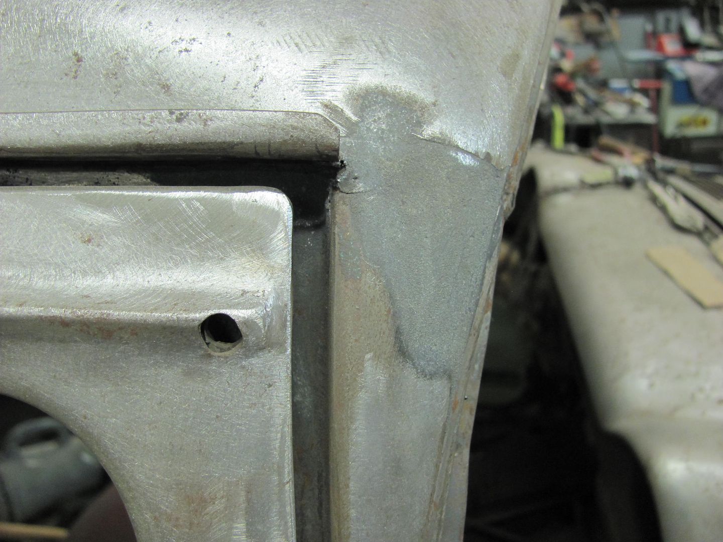
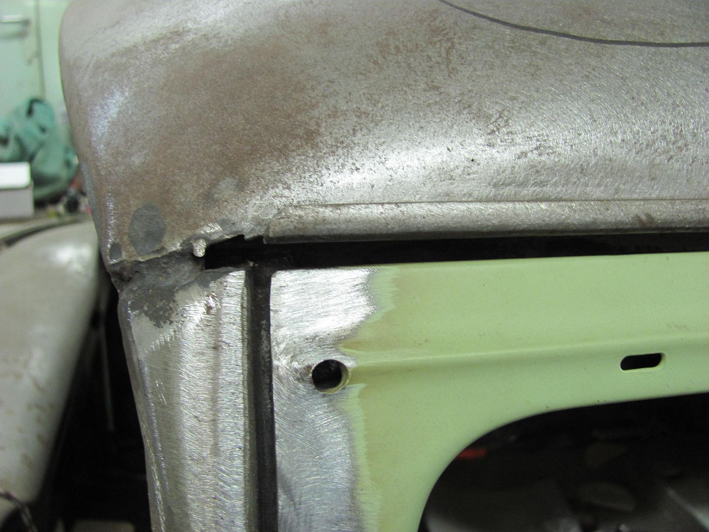
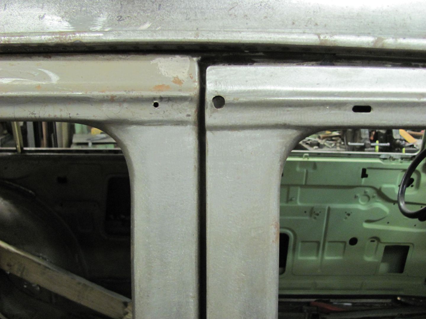
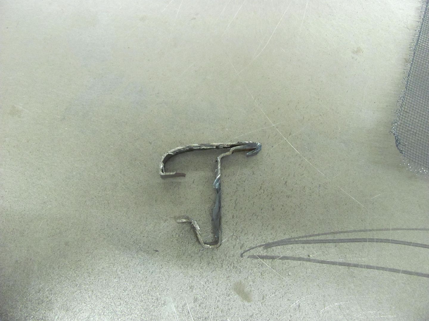
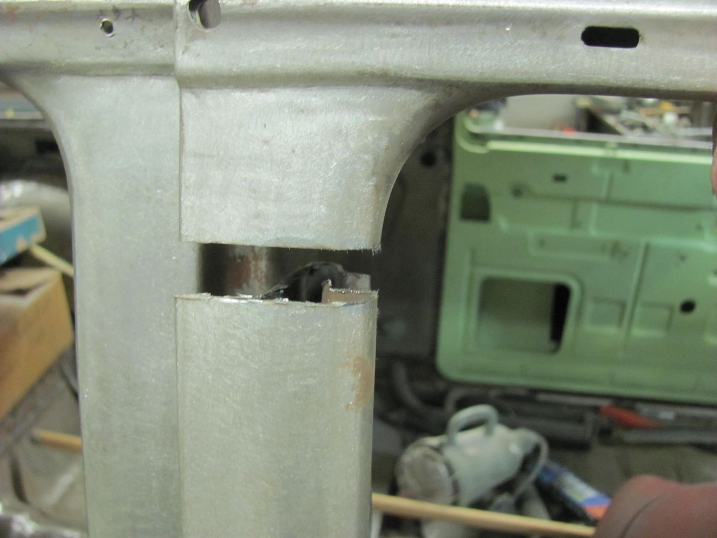
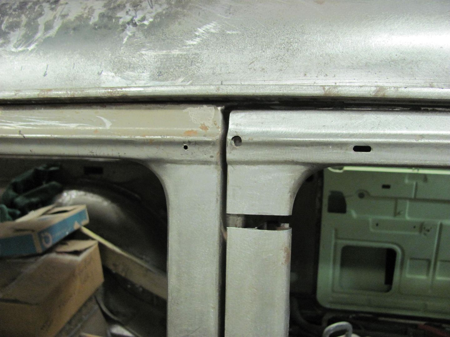
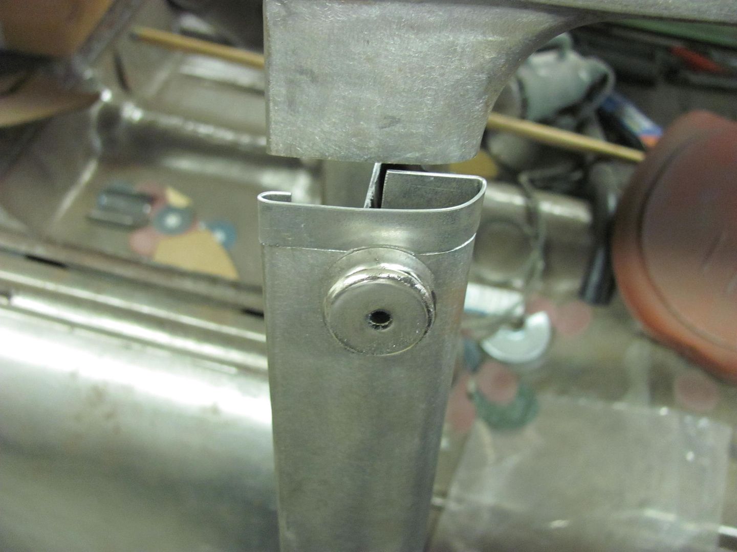
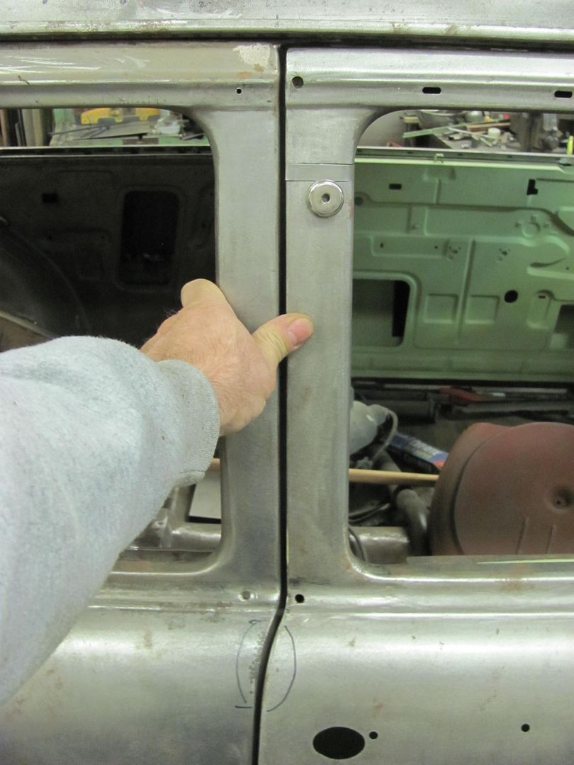
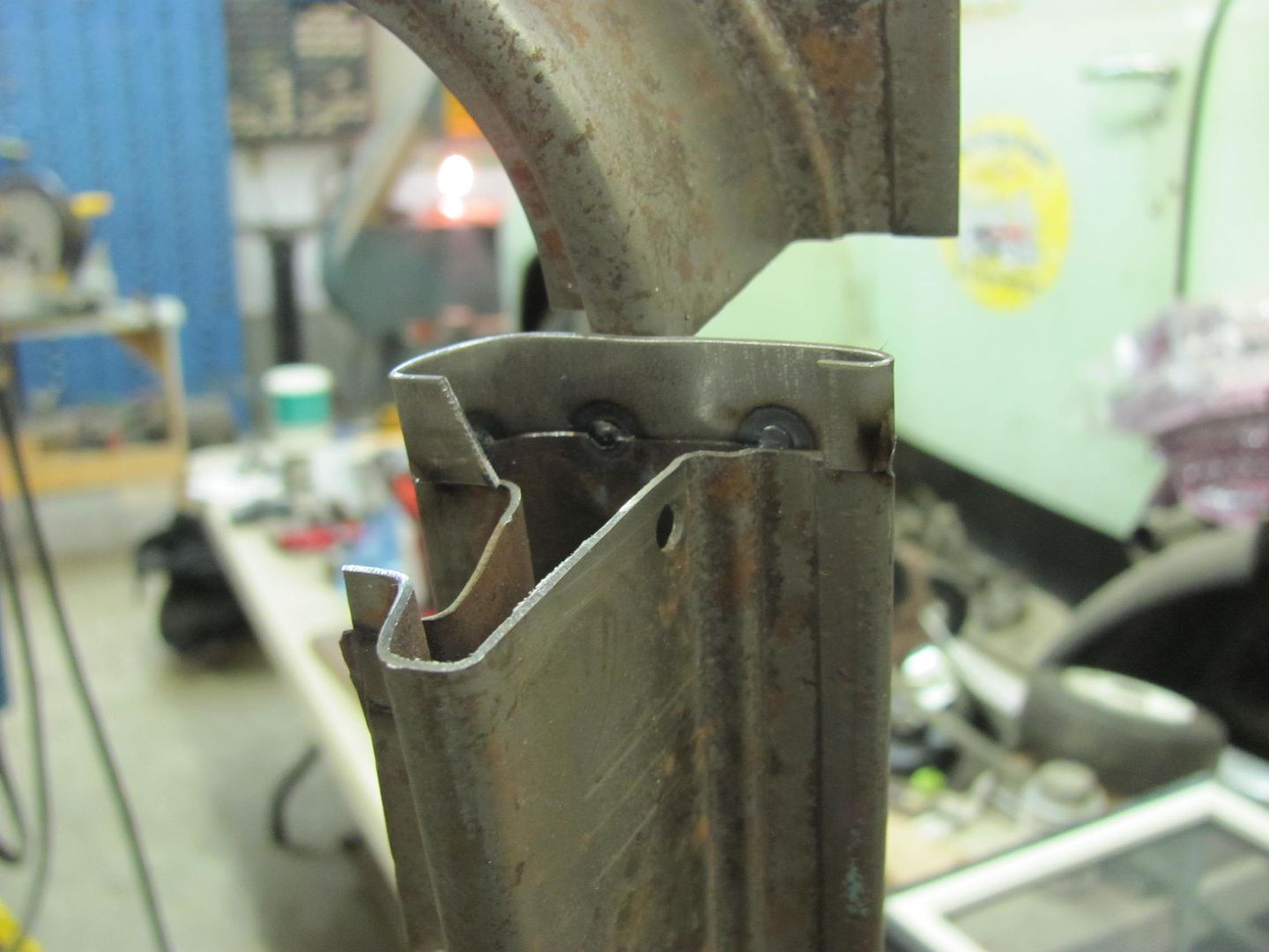
While Kyle continued media blasting fenders, I worked on closed up a gaping hole....
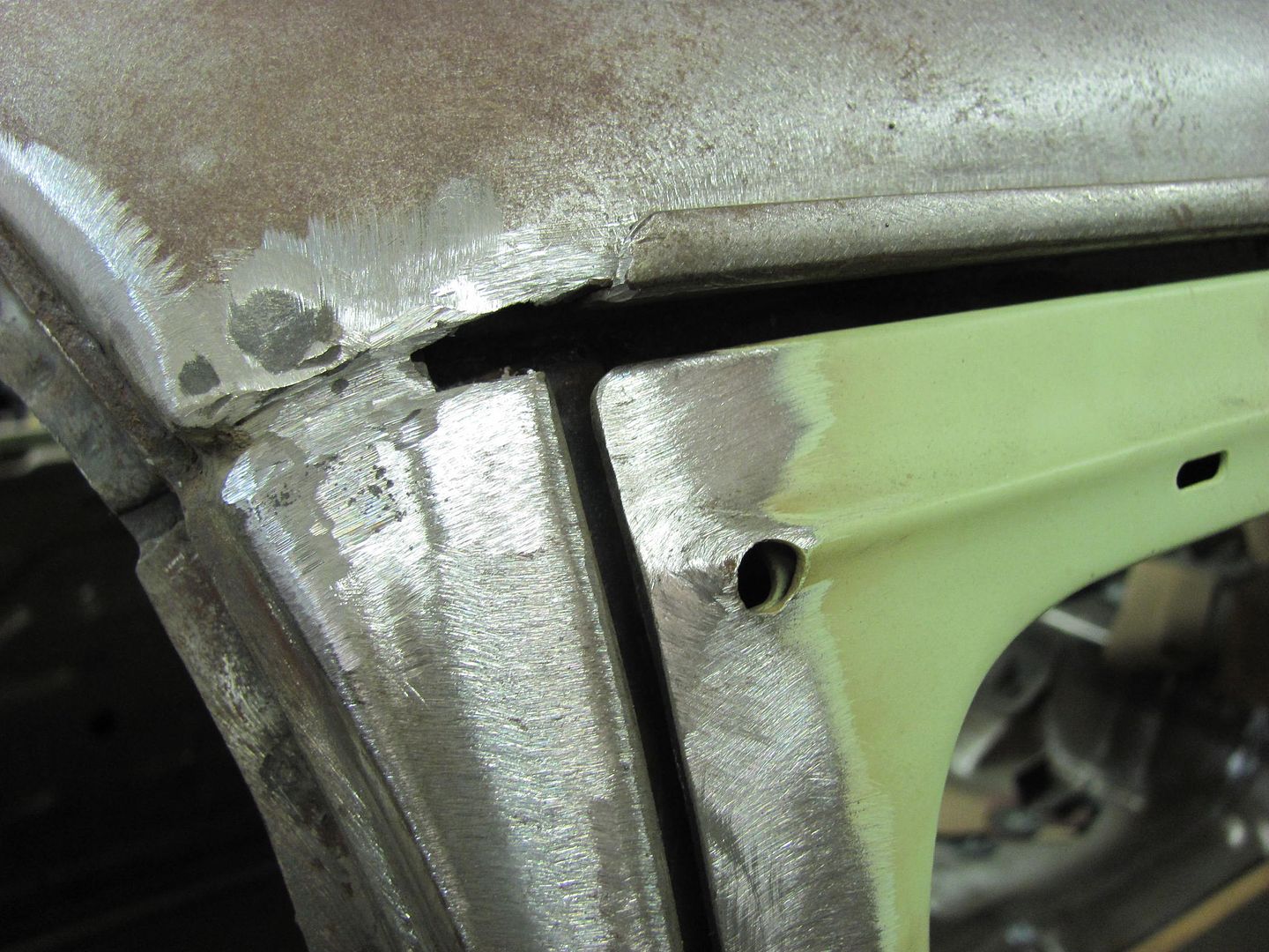
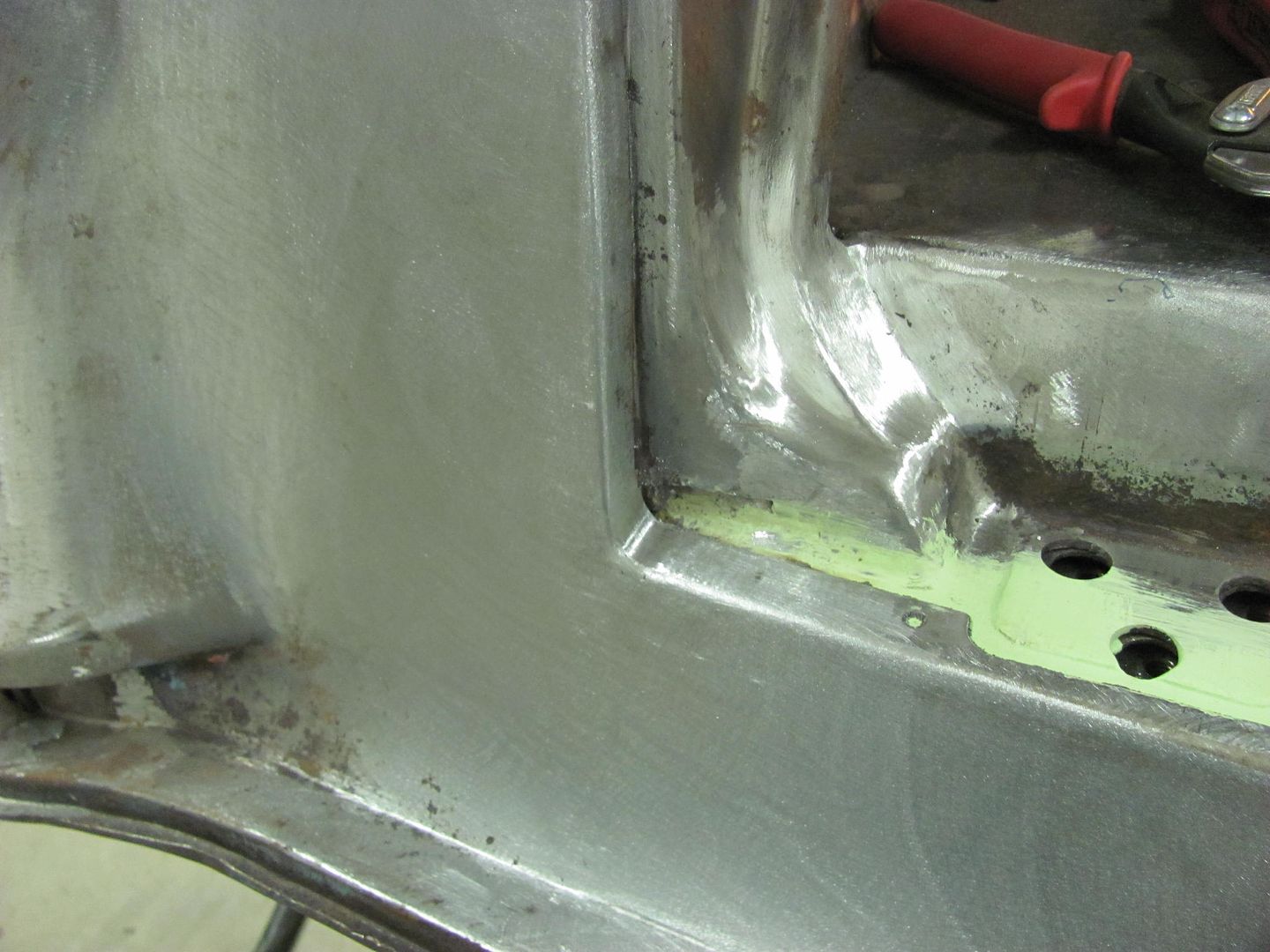
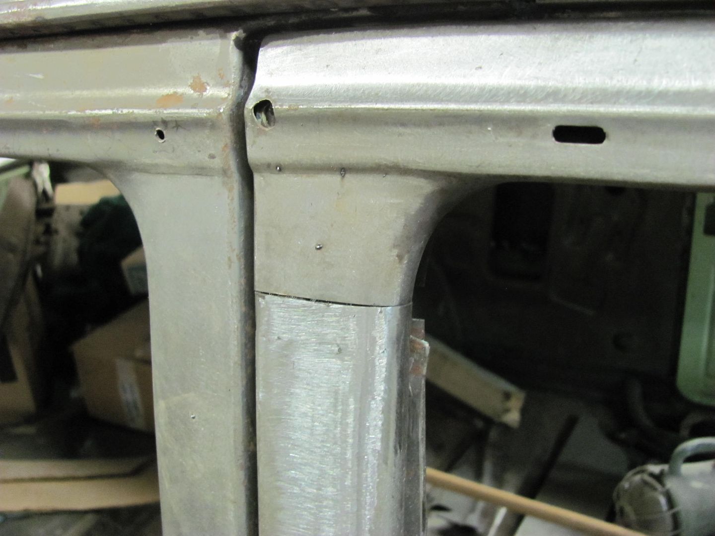
A couple weak spots dictated a bigger hole. Here the radius was added from the A pillar to beneath the drip rail..
Test fit
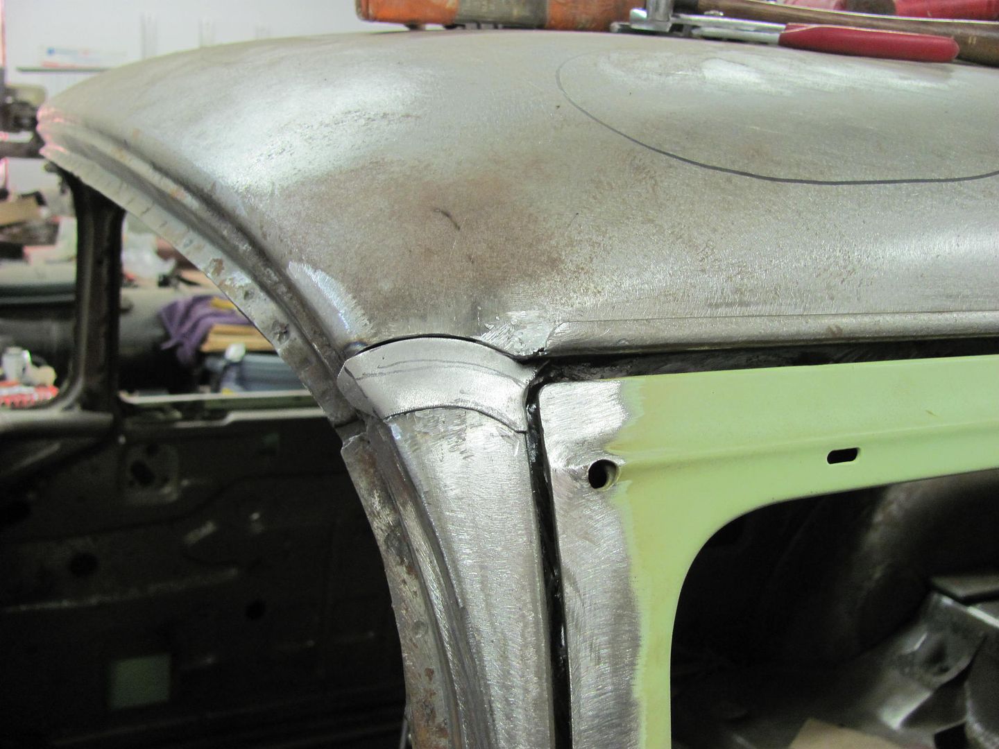
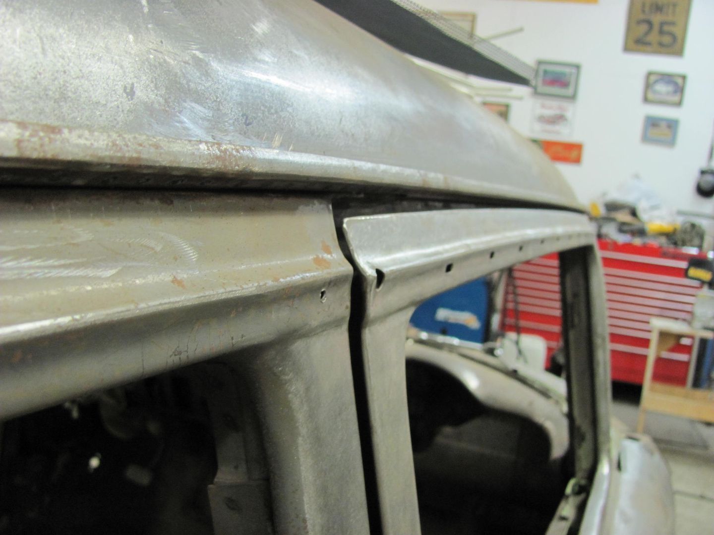
Welded in place.....
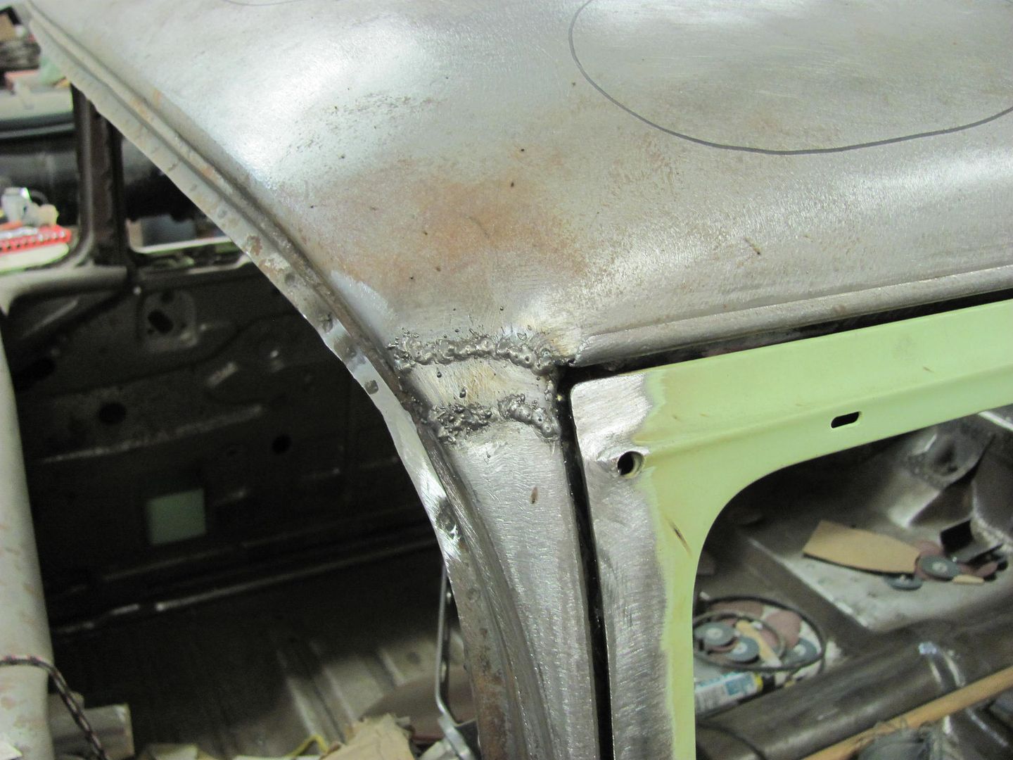
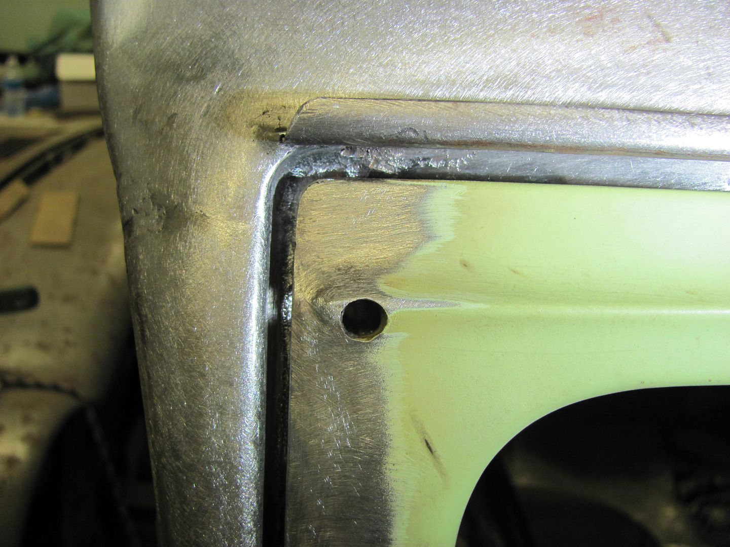
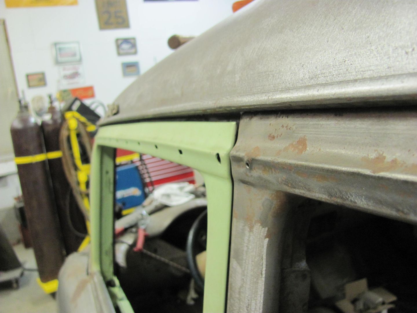
Used a torch and wire brush to clean off the other side, looks like this gap was a factory deal, and we have another radius to install..
A couple weak spots dictated a bigger hole. Here the radius was added from the A pillar to beneath the drip rail..
Test fit
Welded in place.....
Used a torch and wire brush to clean off the other side, looks like this gap was a factory deal, and we have another radius to install..
1971gsfan
Well-known member


 awesome work as usual.
Robert,
Do you think the ER70S-7 rod will work well as filler rod when needed for o/a??
I was thinking of getting some "tig" rods 3/32 to use as filler rods if l need them??
Also in your mig for welding in the patch panels, what diameter wire do you use??
Thanks
Reid
Do you think the ER70S-7 rod will work well as filler rod when needed for o/a??
I was thinking of getting some "tig" rods 3/32 to use as filler rods if l need them??
Also in your mig for welding in the patch panels, what diameter wire do you use??
Thanks
Reid
Last edited:
600SL
Well-known member
Nice work. I will be watching this thread.
wbrian63
Well-known member
I have a question about welding. Seems like I used to be able to do this, and have since forgotten what I did to get good results.
Specifically, when patching a rusty spot, I fashion the replacement out of material that's the same thickness as what it's replacing, sizing the patch to be just a bit smaller than the opening, leaving a small gap between the old & new pieces.
The problem is that I'm unable to generate a welded seam that doesn't have at least a few places where there's erosion at the edge of the weld circle. Not every weld has the problem, but enough do to make it irksome.
I have a Hobart 187 welder, and I'm using .023 solid wire (Hobart or Lincoln brand sourced from Northern Tool) with standard MIG gas. I've tried turning down the heat (no variable heat on this model, distinct switch positions) to 1 and increasing wire speed. I've tried turning the heat up to 2 and messing with wire speed - results are the same.
The erosion is Very Very small - when the weld is ground away, I can feel it with the point of a carbide scribe, but it's invisible to the touch.
The erosion isn't limited to the old metal - it happens on both pieces.
I have several places where I've patched in pieces on this project car where the results are outstanding - no visible indication where new metal meets old.
When you're tacking panels together, do you hold the nozzle still, or do you sweep or stir it a bit?
I'm thinking it's a technique thing, and possibly an issue with the quality of the welder.
Appreciate any suggestions.
Last edited:
wbrian63
Well-known member
I follow your method of using a narrow cutoff wheel in my grinder to dress the welds down to just above the surrounding metal. This is done after each set of welds is added until I've got a fully completed seam. Then I use a flap disc to finish the work.
Typically, at one or more places along the seam, I'll see little "halo's" around a few weld points. It's as if the arc scoured the adjacent metal and there wasn't enough filler metal being fed into the arc. However, turning up the wire speed typically just results in a fatter blob of metal being deposited. Turning up the heat to help spread the filler helps somewhat, but the rings still persist. If I turn the heat up too far, of course I blow holes in the panel.
Typically, when I try to fix the problem, I cover up the blemish with a weld, only to have the same problem with the new weld...
I've done a LOT of welding on this project of mine. There are many locations where I've got seams that are nearly invisible.
There are an equal number of seams where there are numerous little crescent-shaped images in the metal.
As I said earlier, these divots (looking for the right term to describe it - divot may be too harsh) are really shallow - you can't catch a fingernail on them, and closing my eyes and running my fingers over the weld reveals nothing. I can feel them by using the tip of my carbide scribe, but that's all.
I know all this will disappear under primer and stone chip (most all of this work is only visible from underneath the car), but it still irks me.
It's gotta be a combination of heat and wire speed.
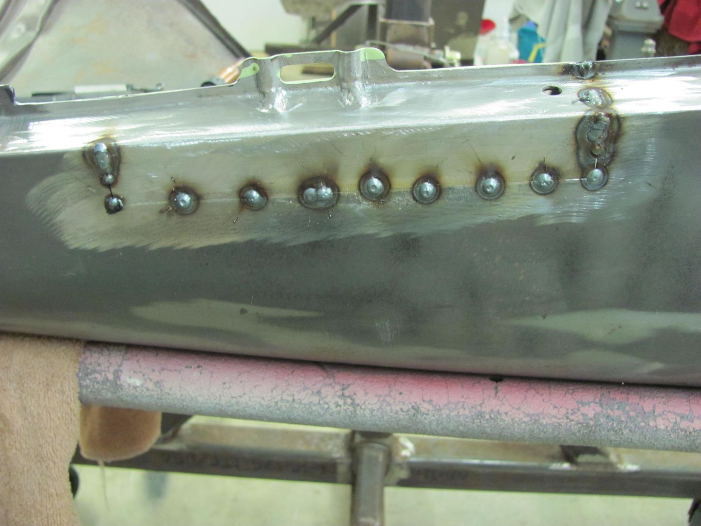
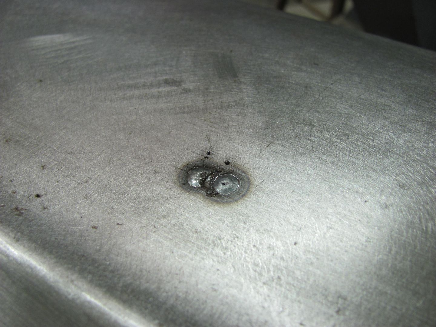
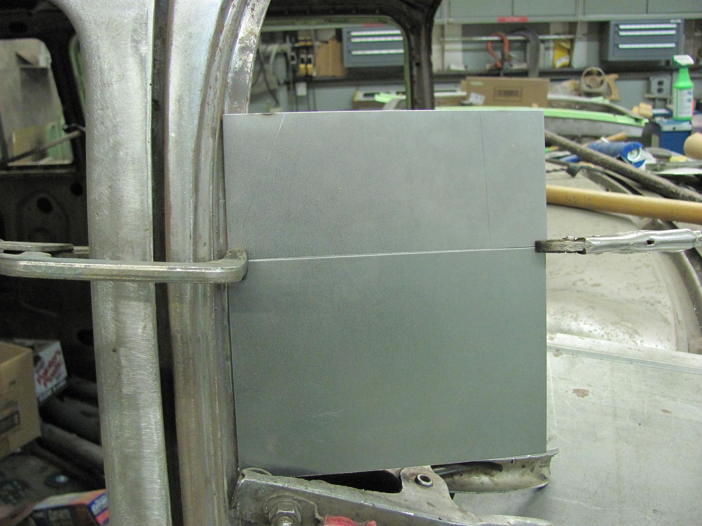
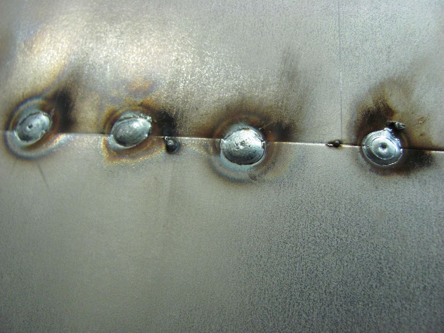
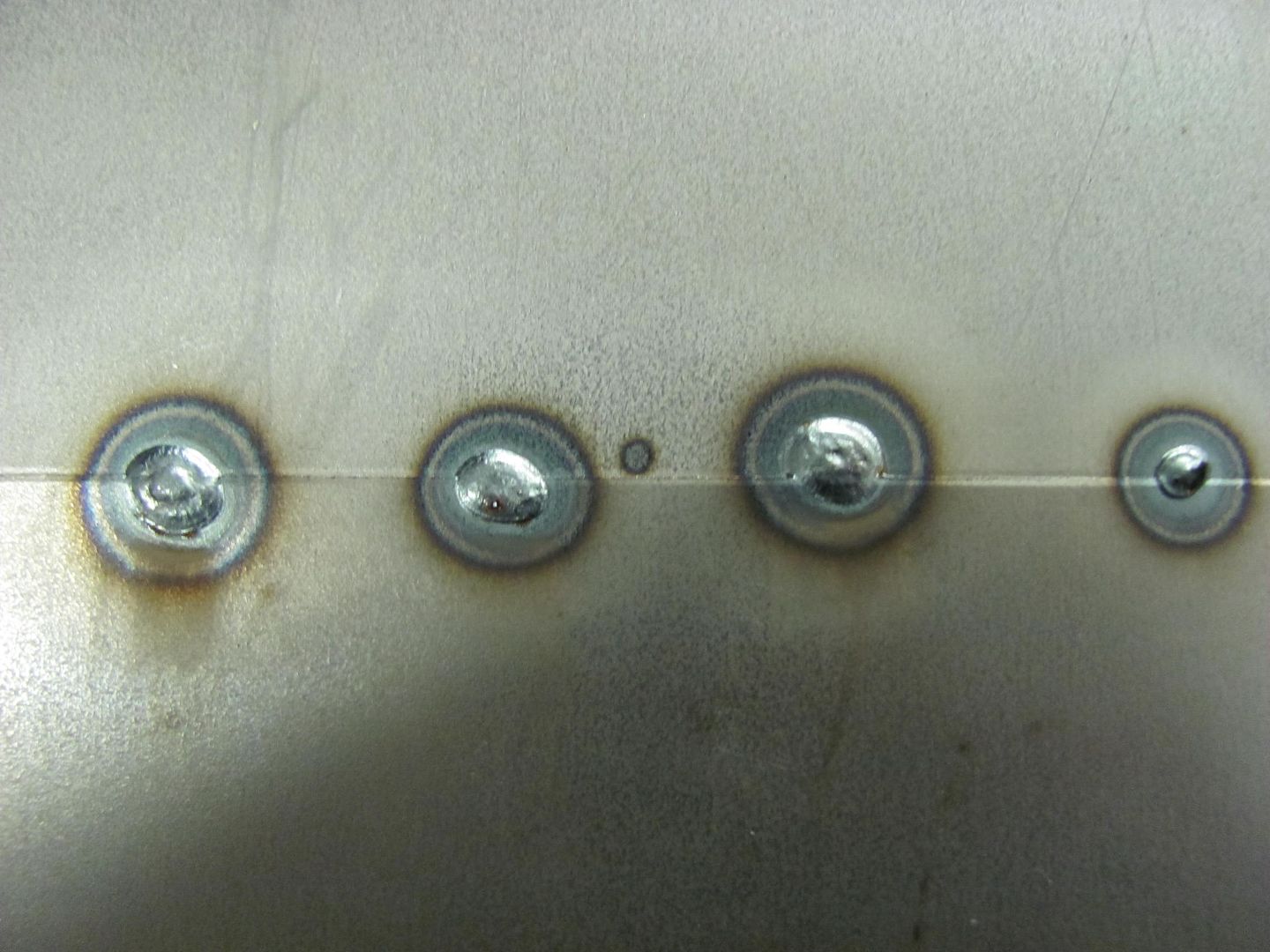
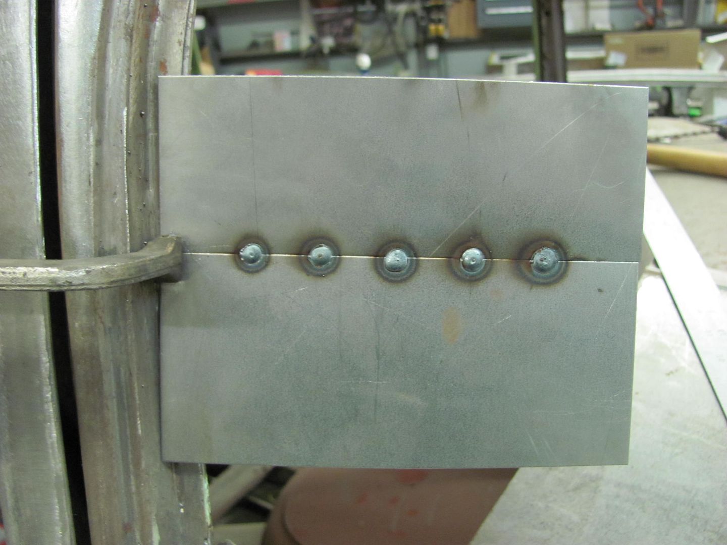
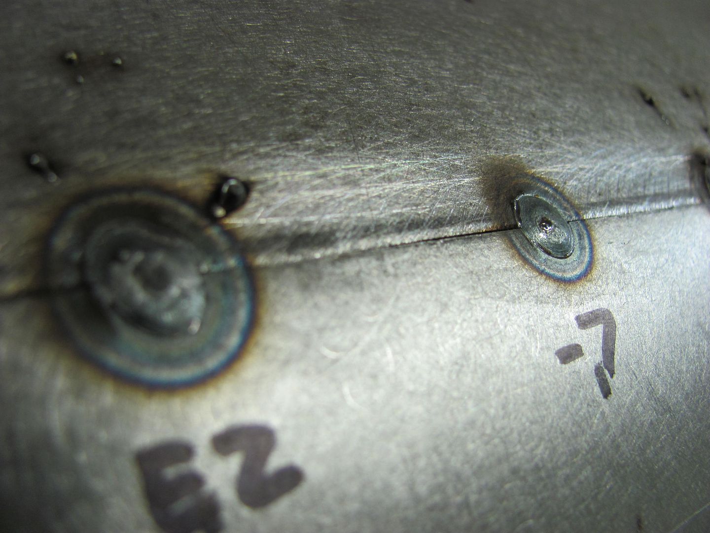
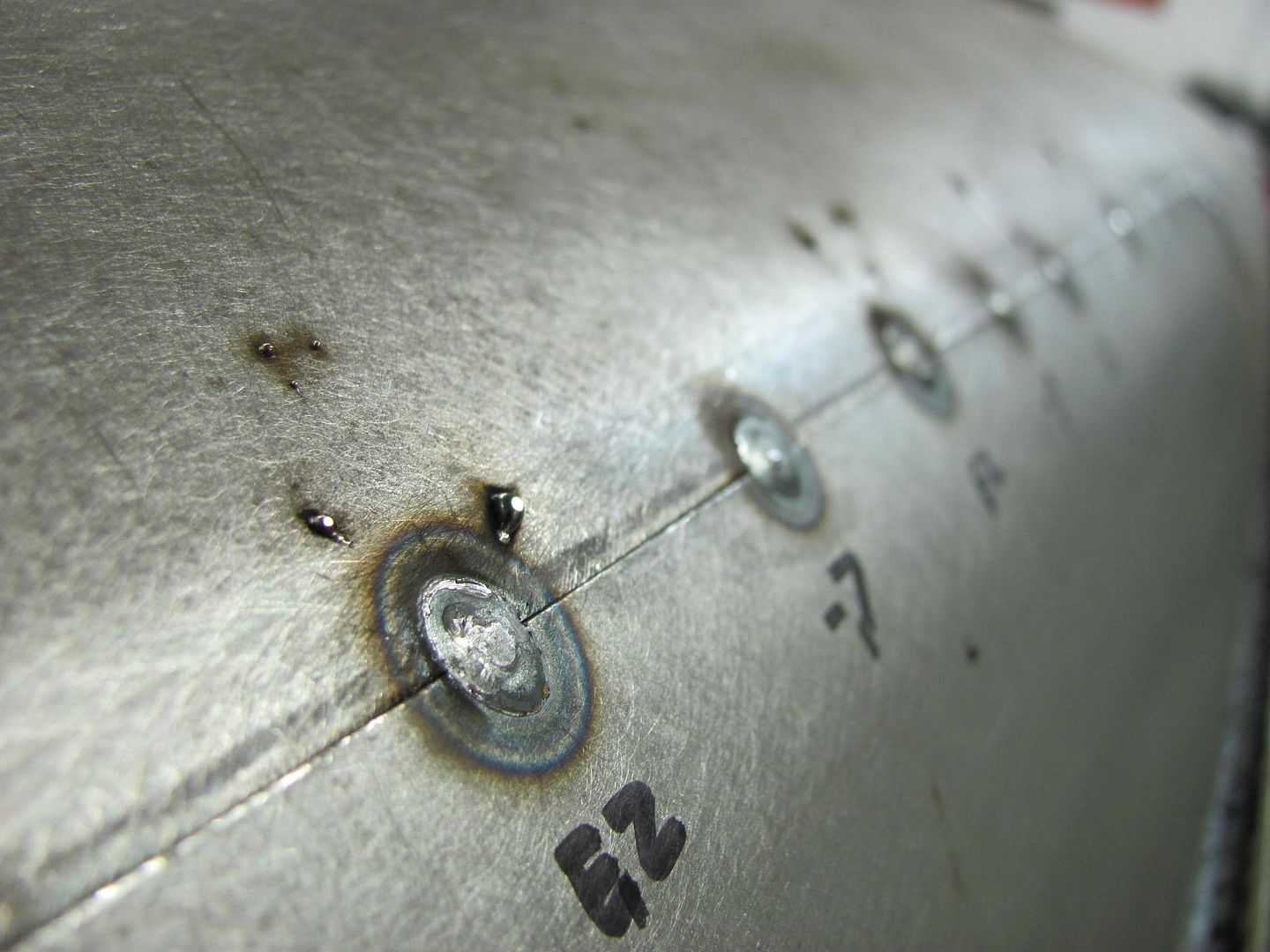
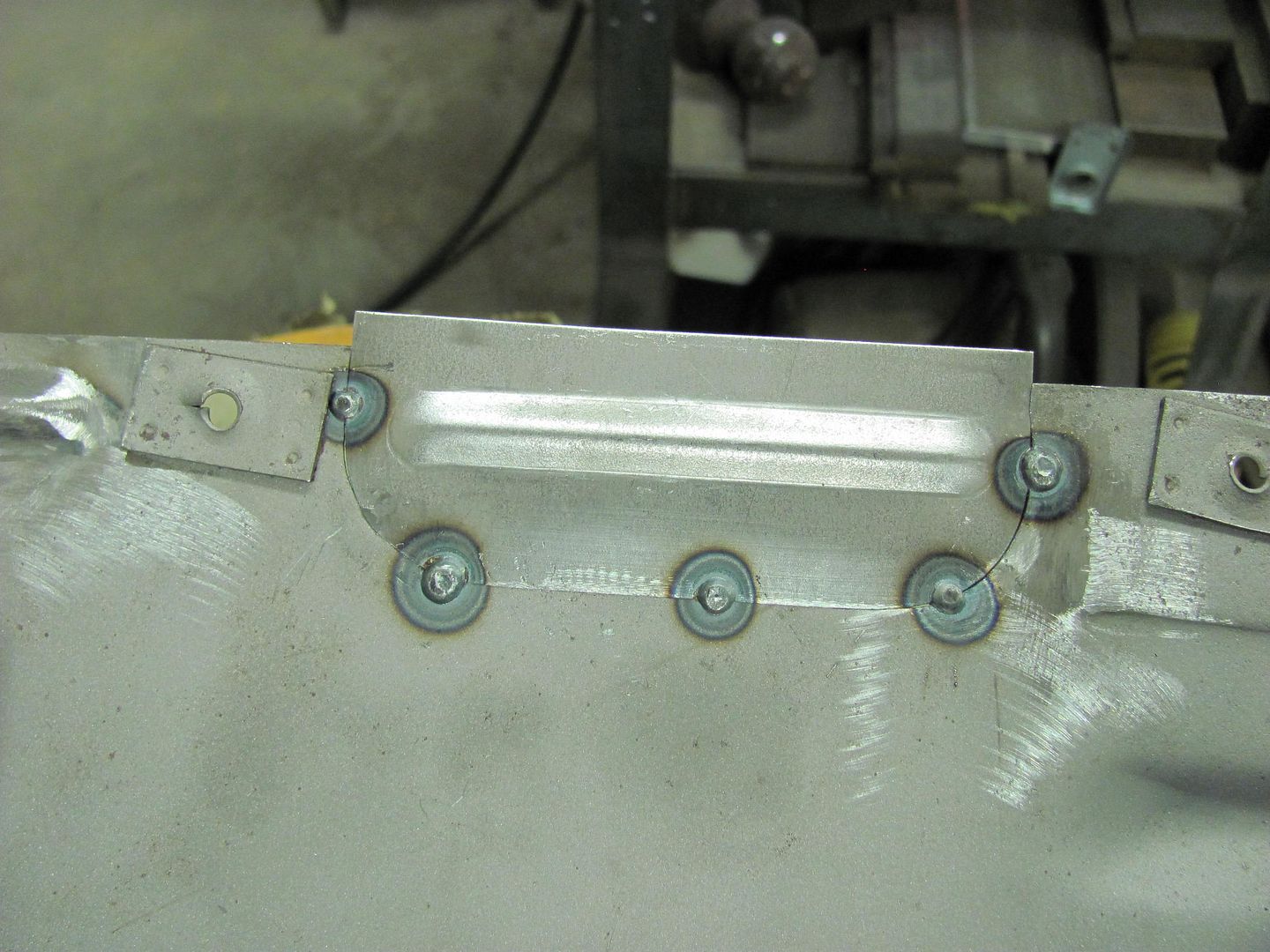
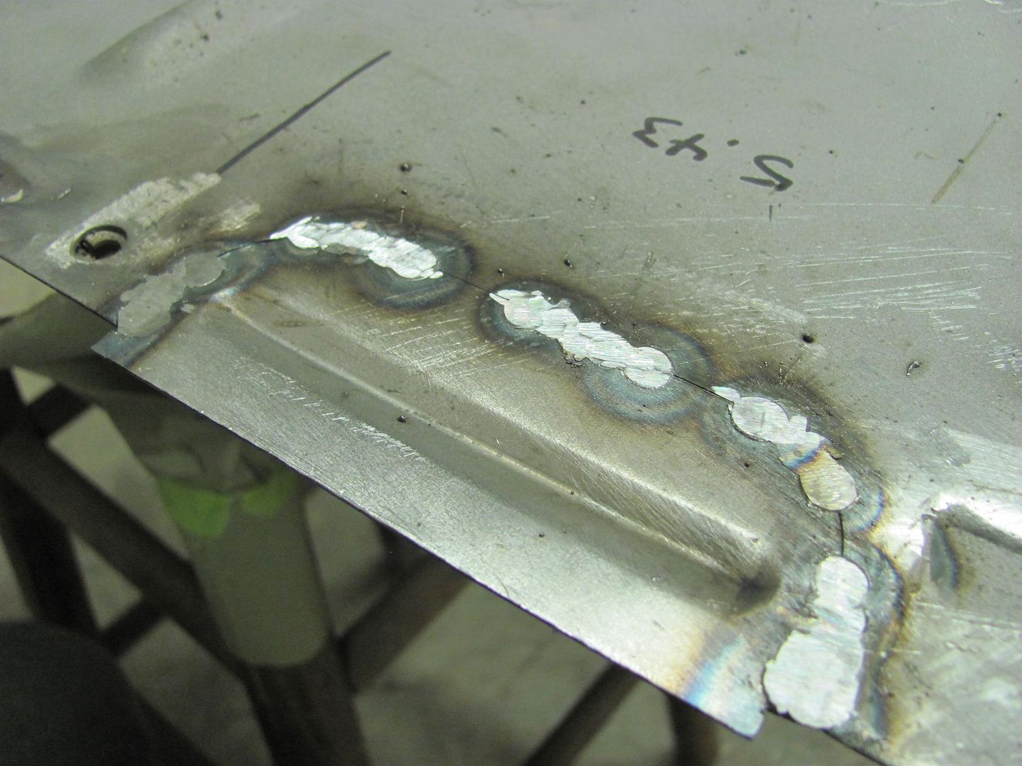
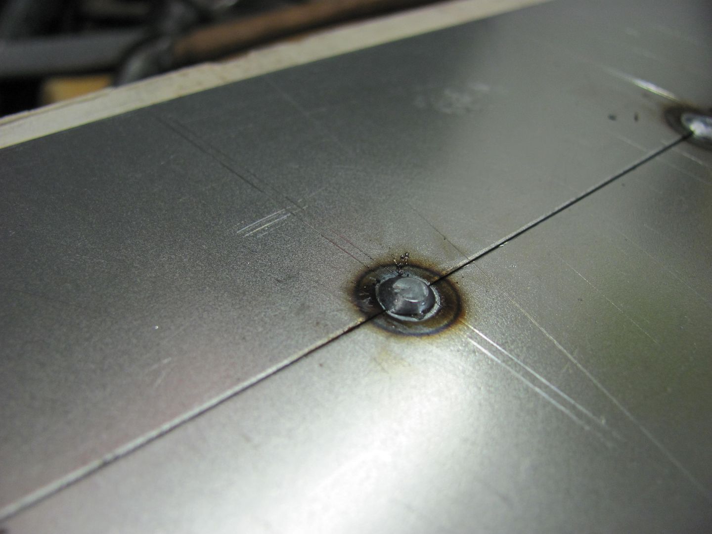
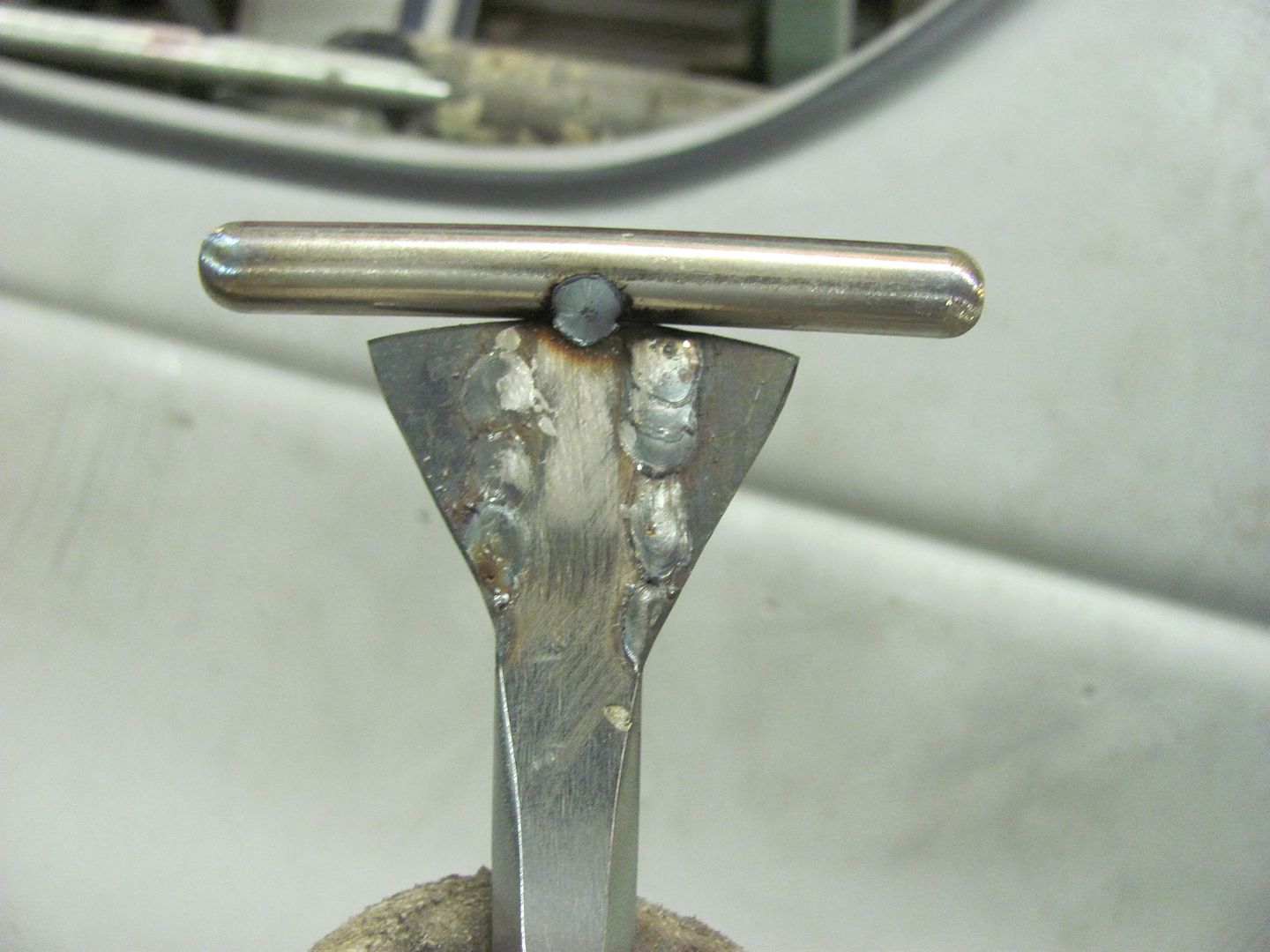
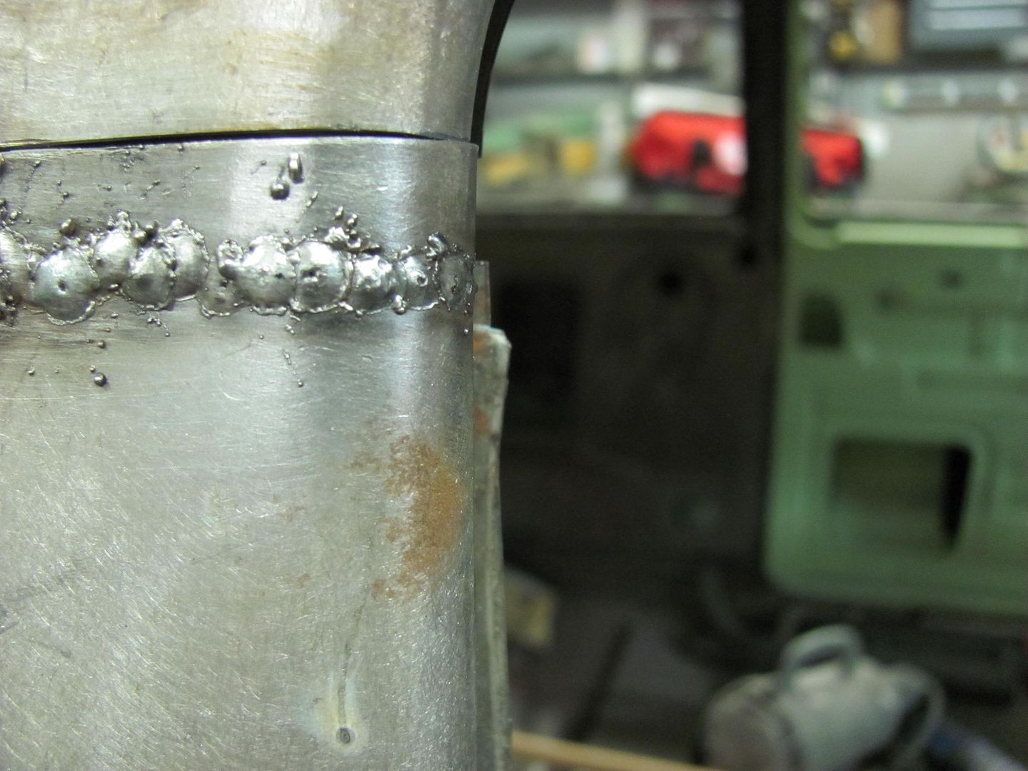
It sounds like you are referring to a bit of undercutting around the perimeter of the metal, which may be a lack of wetting.. Here are two samples I've done, one using .023 EZ grind, one using .035 ER70S-7, both set for 3/16" steel thickness, feed speed adjusted accordingly, and heat and weld size is controlled by time of trigger pull. Both show similar results, but I did find I liked the -7 wire better for flowout into the panel.
I'm using EZ grind in the new welder presently, and have noticed some of what you describe, especially in the emblem holes that were filled on the front fenders in post 923 on previous page. It was a minimal "undercut" at the perimeter, so should not pose any issue and as you said, primer will take care of it. The emblem holes were filled with the welder set for 16 ga metal, the test coupons below, although I didn't grind them flush, seemed to not have this issue, and they were set for 3/16 thick steel. I would suggest to try increasing the heat even more, adjust the feed to prevent blowout, and use length of trigger pull to control weld size. I don't think that you need to go as high as 3/16 heat setting, but it does show that setting your welder up for 16 or even 14 ga should be very manageable. See if the higher heat setting affects the undercutting you are experiencing, whether that be better or worse.
I think too many people are of the mindset that you can only control the heat by using the heat control knob on the machine. Keep your heat turned up, control the heat the panel sees with trigger pull duration. Turning down the heat starts to move you toward compromising weld penetration.
Eventually I want to go back to some -7 wire in this new machine, it seemed to have less issue with the undercutting than what the EZ grind showed the other night.
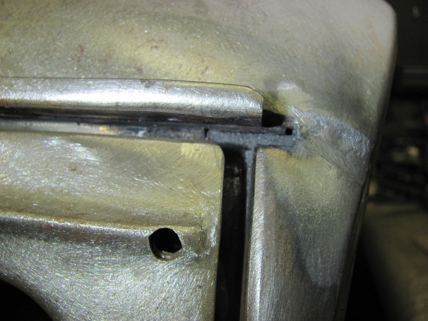
Well today I had a phone call from 3 Mules to tell me the .023 welding wire was in. I had ordered .023 ER70S-7, but what actually showed up was EZ Grind. I guess I was destined to try this stuff out...
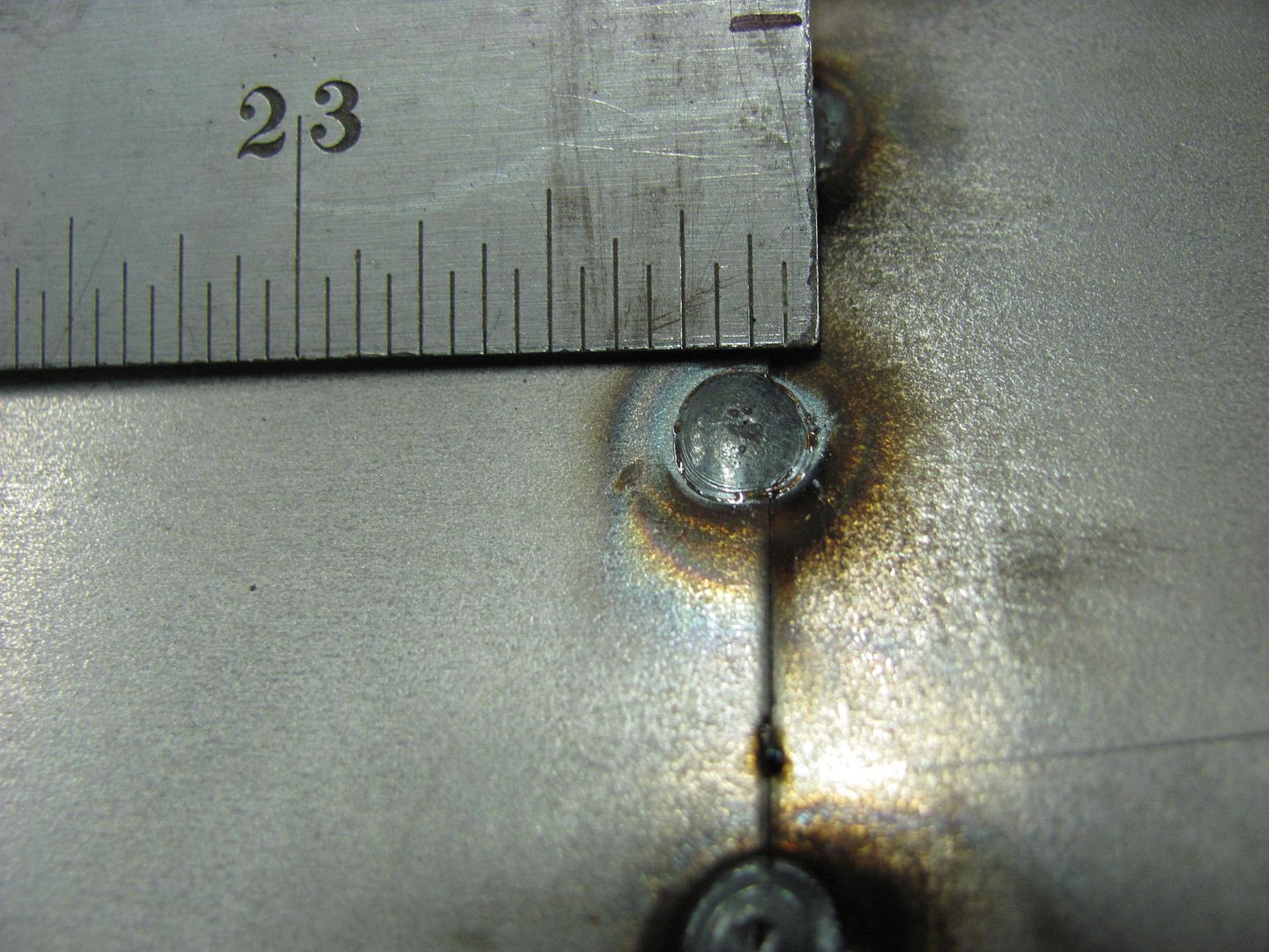
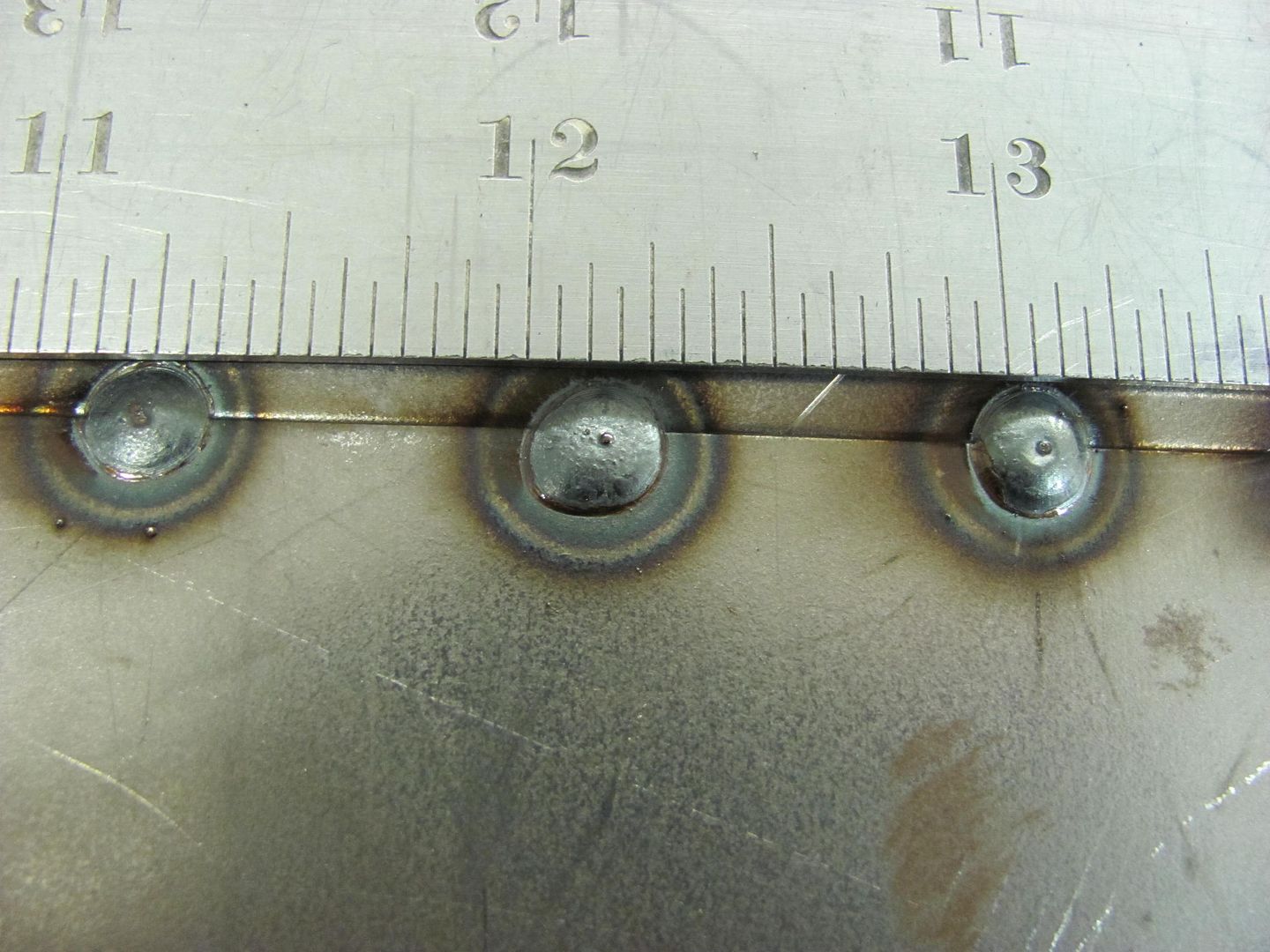
After about 45 minutes of changing wire, rollers, and trying different settings on the machine, we found dialing it in for 3/16 thick steel and using 1/2 second weld "application" showed about the best results.. Seems odd as the metal was 19 ga, or about .038 thick..
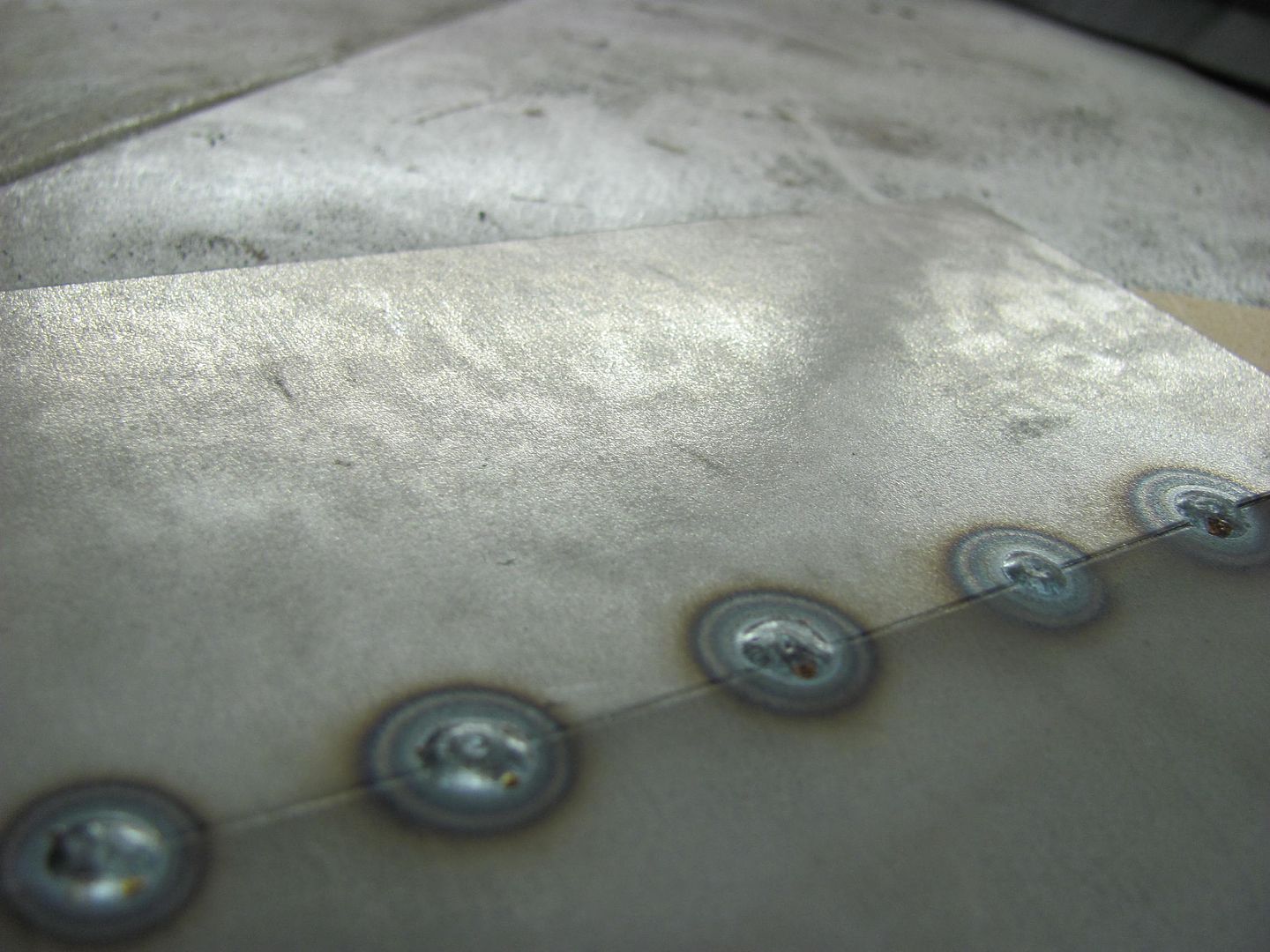
front:
rear:
Comparative size of the weld proud.

I wasn't totally pleased with the .023 EZ grind, but in all fairness I think some of the issue is my welder. It never has been too keen on .023 wire.
Put the .035 ER70S-7 back in, dialed in the settings for 3/16 thick steel, and ran some test welds...
Front side....
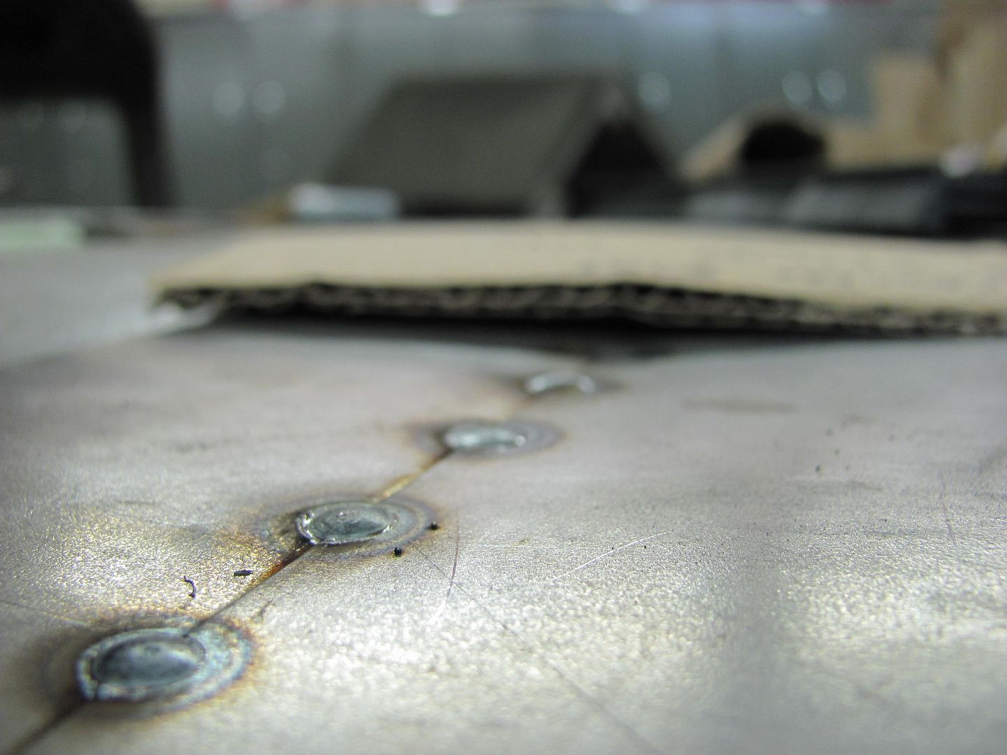
Rear side....
Comparing the EZ grind to the -7 in the roof repair shows less splatter with the -7...
Last edited:
More progress, although it doesn't appear like much, progress just the same...
Door skins had been left "loose" on the inner door to allow twisting/tweaking for fitment within the door opening. Drilled some 3/16 holes from flange into inner door and plug welded. I've had many people ask how well the epoxy primer holds up to the heat of plug welds, here is a good indicator. It shows discoloration at the surface, but note the nice green primer underneath where the grinding wheel went through the paint..
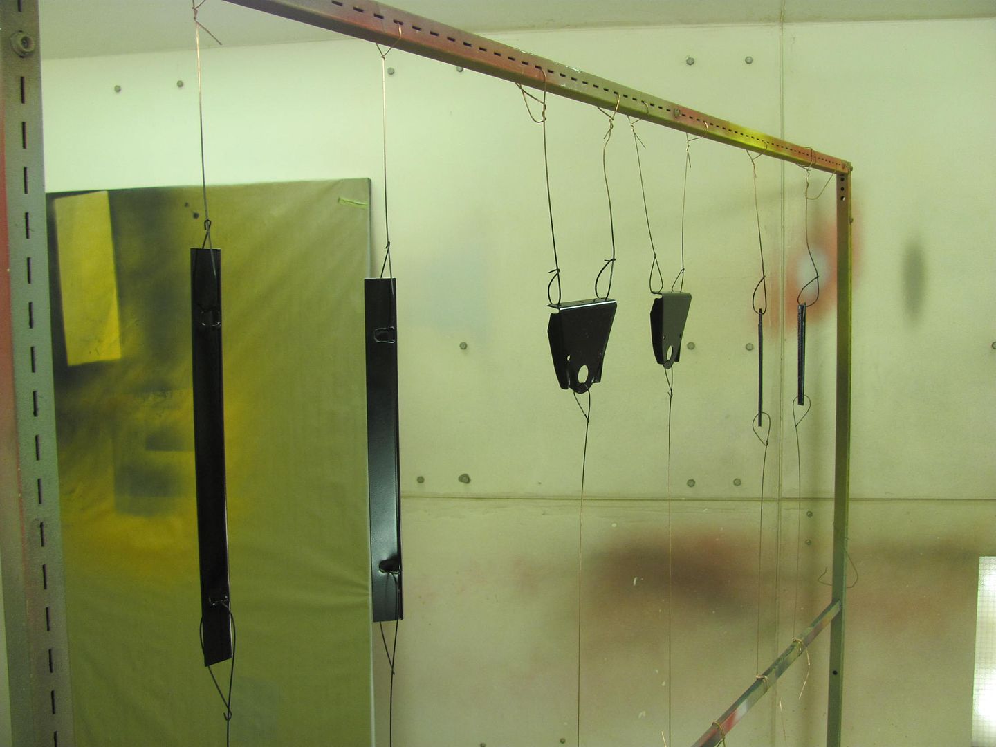
Parts ready for epoxy primer..
These are the stiffeners for inside the door skin that go behind the door handle. The inside of the door will be sprayed, as well as these parts, and allowed to flash. Then another application on both and they'll get bolted in place, letting the epoxy primer act as an adhesive to hold in place and seal to the door skin. Once door handles are bolted on they will be there for good..
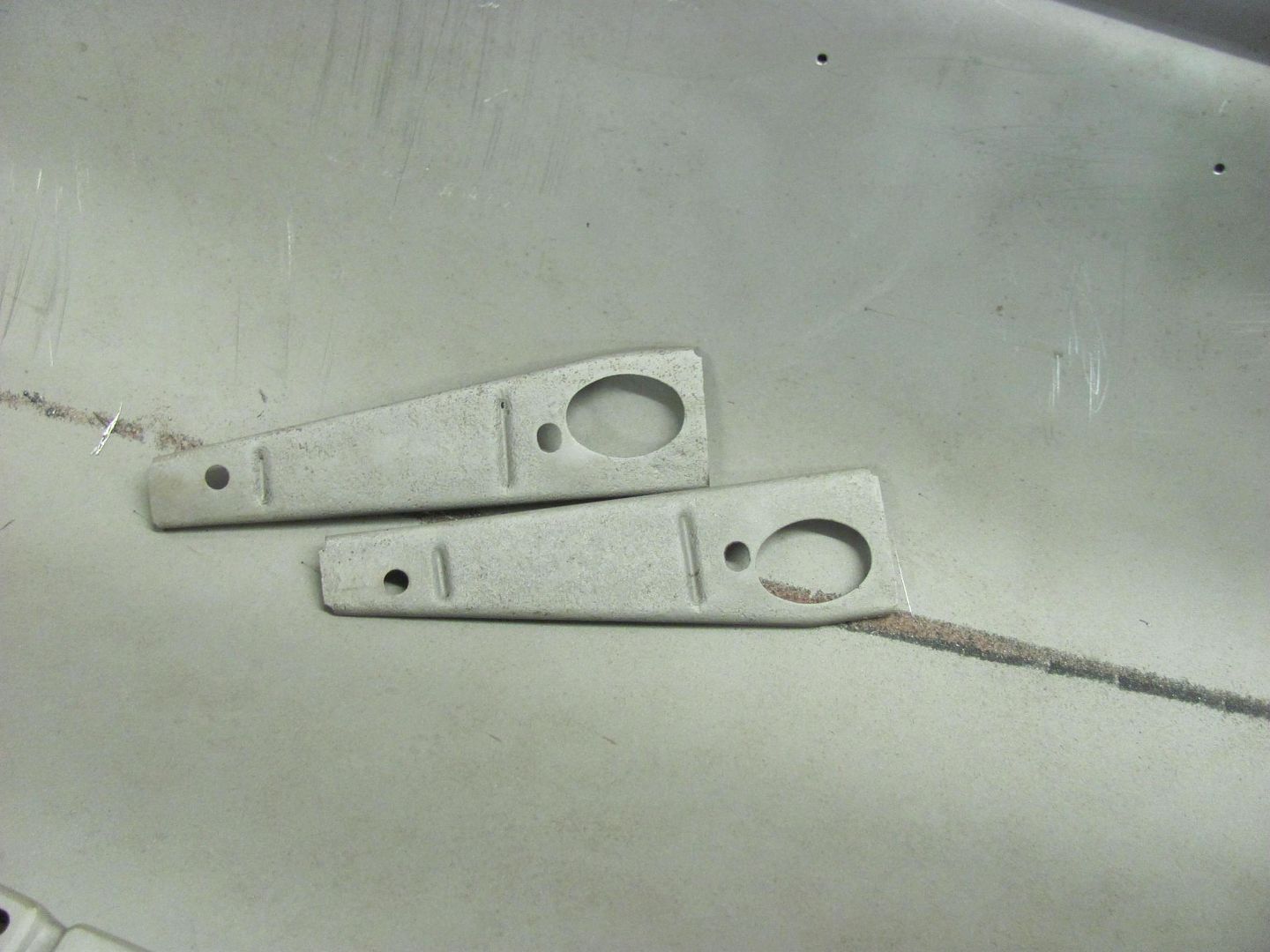
This car has belt line trim that goes around the perimeter of the bottom of the windows, which needed to be added to the new door skins. I had saved a piece from the old door skins to get the locations correct. Here's the layout of the slots for the stainless attaching hardware, we'll get that finished next time..
Door skins had been left "loose" on the inner door to allow twisting/tweaking for fitment within the door opening. Drilled some 3/16 holes from flange into inner door and plug welded. I've had many people ask how well the epoxy primer holds up to the heat of plug welds, here is a good indicator. It shows discoloration at the surface, but note the nice green primer underneath where the grinding wheel went through the paint..
Parts ready for epoxy primer..
These are the stiffeners for inside the door skin that go behind the door handle. The inside of the door will be sprayed, as well as these parts, and allowed to flash. Then another application on both and they'll get bolted in place, letting the epoxy primer act as an adhesive to hold in place and seal to the door skin. Once door handles are bolted on they will be there for good..
This car has belt line trim that goes around the perimeter of the bottom of the windows, which needed to be added to the new door skins. I had saved a piece from the old door skins to get the locations correct. Here's the layout of the slots for the stainless attaching hardware, we'll get that finished next time..
wbrian63
Well-known member
It sounds like you are referring to a bit of undercutting around the perimeter of the metal, which may be a lack of wetting..
"Undercutting" - that's exactly what I'm talking about.
The metal thickness I'm dealing with is around that .038 area - maybe up to .045 - don't remember.
I've got some .035 wire - I'll swap over to that and turn the heat up a bit.
My trigger time is typically very short - just enough to get good penetration.
A question about planishing the welds. You planish before you grind, right?
If that is the case, how do you keep from deforming the face of the panel when the backing block and the underside of the weld don't align perfectly?
I've had many situations where I've had to do a lot more work to get rid of "ripples" around the welds where there once was a nice flat panel. For the longest time I couldn't figure out what was causing the deformation - I thought it was heat, but then I realized that when I was planishing the weld, I actually drove it down or off at an angle due to poor alignment on the backing block, and in doing so, bent the panel as it followed the weld.
My latest patching effort I actually did zero planishing, allowing about 1/32 gap between the panels and taking my time with welding and grinding. With the exception of the erosions, there were no issues with dimpling.
Thanks for all your help to this point.
Responses in blue
It sounds more than anything that you just need to work on your hammer and dolly methods to eliminate the panel deflection. It also may be a case of too much planishing. We're primarily only trying to negate the shrinking effect at the point of initial planishing. Don't try to do it all right at the starting gate.
"Undercutting" - that's exactly what I'm talking about.
The metal thickness I'm dealing with is around that .038 area - maybe up to .045 - don't remember.
I've got some .035 wire - I'll swap over to that and turn the heat up a bit.
My old machine was a beast and didn't play well with smaller wire. I don't know that the wire change will help you, and normally try to dissuade people from going out and buying a new roll just because someone else is using something. In this case, you already have it, so please share any results if you could.
My trigger time is typically very short - just enough to get good penetration.
A question about planishing the welds. You planish before you grind, right?
Typically, yes. Each weld dot will shrink and pull the surrounding panel circumferentially. By planishing as it is sitting there by its lonesome, you can more readily negate these effects.
If that is the case, how do you keep from deforming the face of the panel when the backing block and the underside of the weld don't align perfectly?
With any dolly that is used in a hammer-dolly operation, the dolly should closely match the contour of the panel it is held against, without corners touching. So if the panel is flat, the dolly should just off of flat, where the perimeter of the dolly does not touch, only the face in the center. In this fashion, the dolly touches weld proud on the back side, the hammer touches weld proud on the front side.
I've had many situations where I've had to do a lot more work to get rid of "ripples" around the welds where there once was a nice flat panel. For the longest time I couldn't figure out what was causing the deformation - I thought it was heat, but then I realized that when I was planishing the weld, I actually drove it down or off at an angle due to poor alignment on the backing block, and in doing so, bent the panel as it followed the weld.
As you indicated, poor alignment of the dolly. If you don't want deflection of the weld and thus the panel, the face of the dolly should be parallel to the panel surface, as should be the hammer face.
My latest patching effort I actually did zero planishing, allowing about 1/32 gap between the panels and taking my time with welding and grinding. With the exception of the erosions, there were no issues with dimpling.
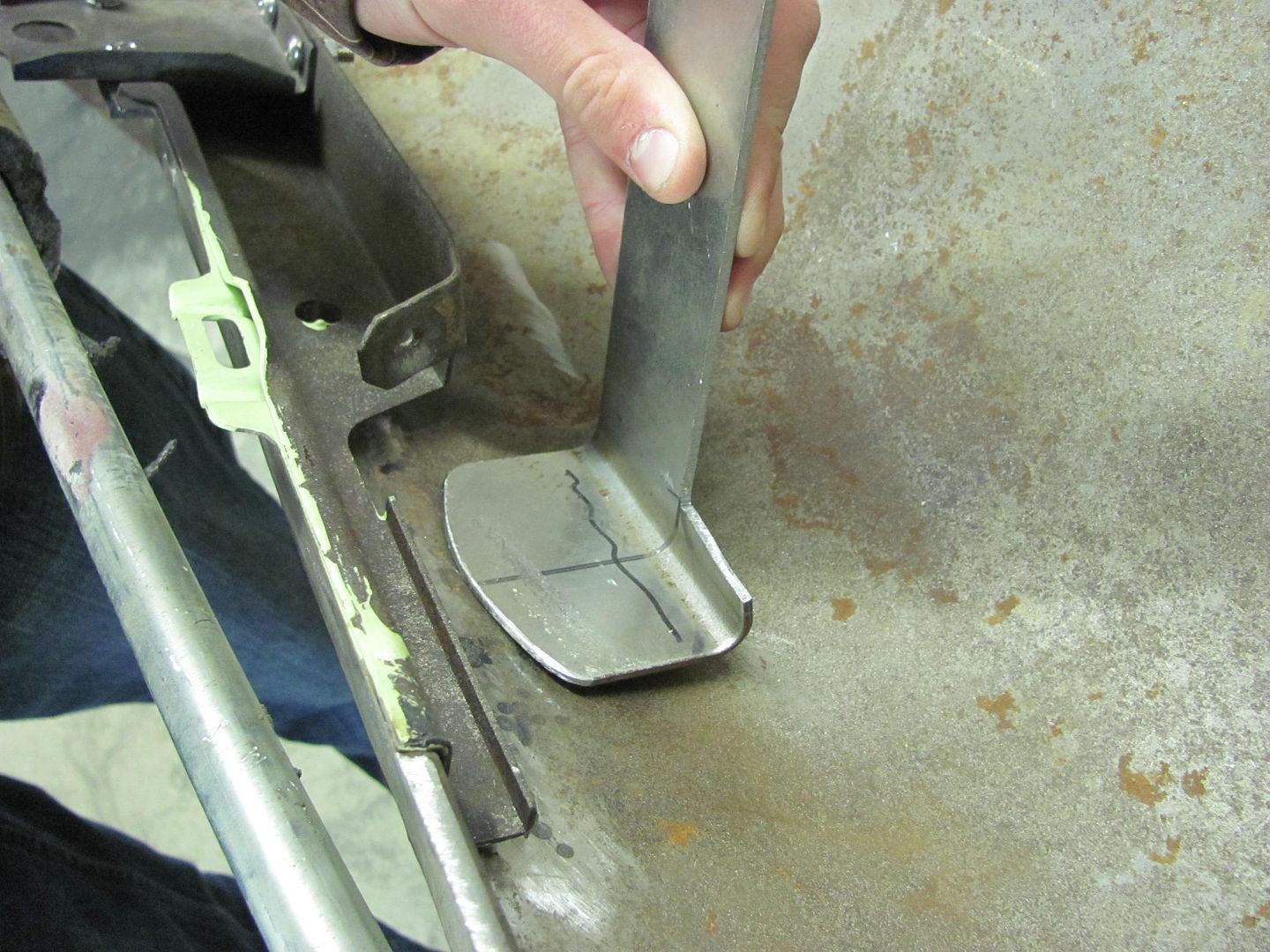
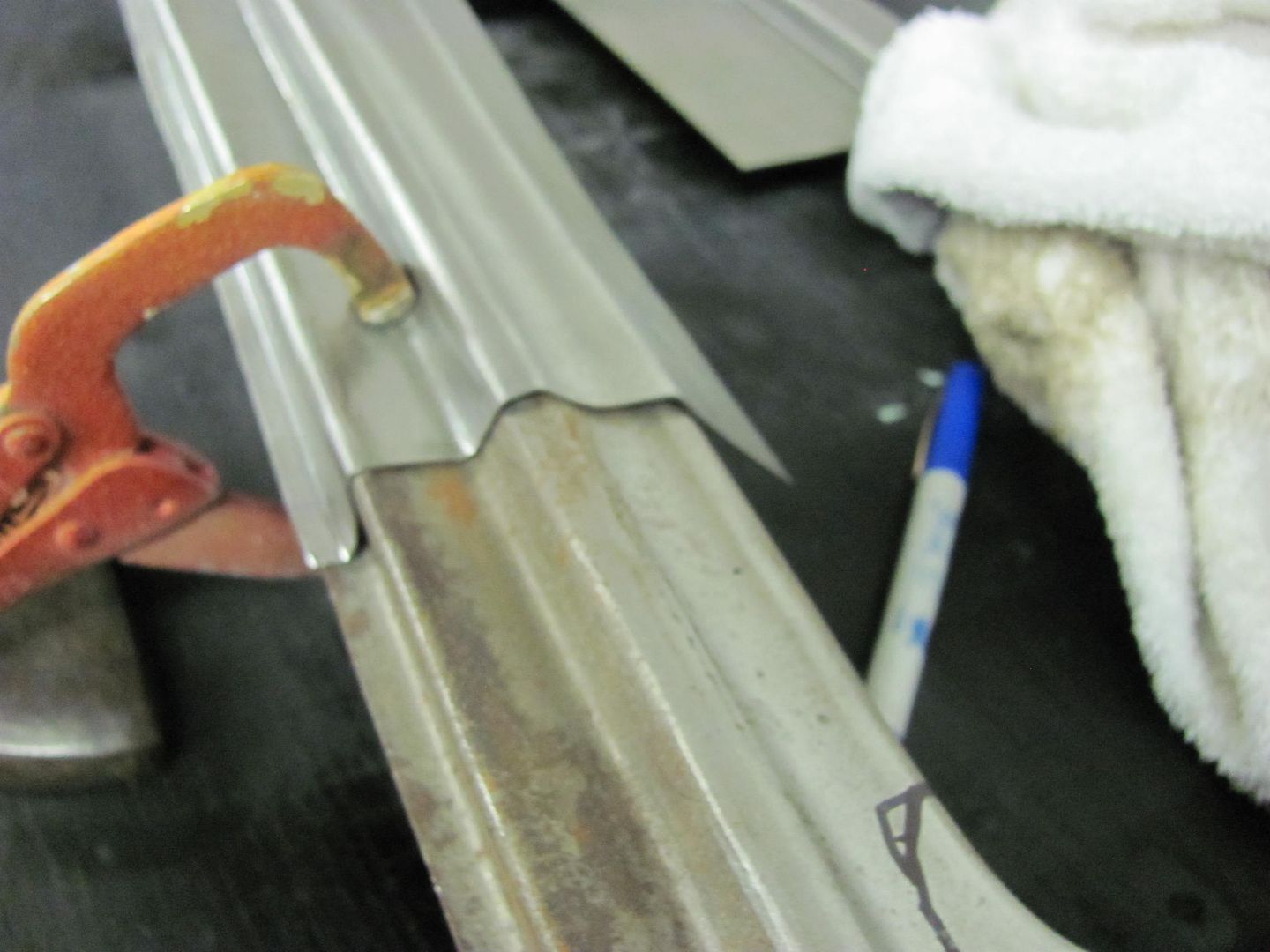
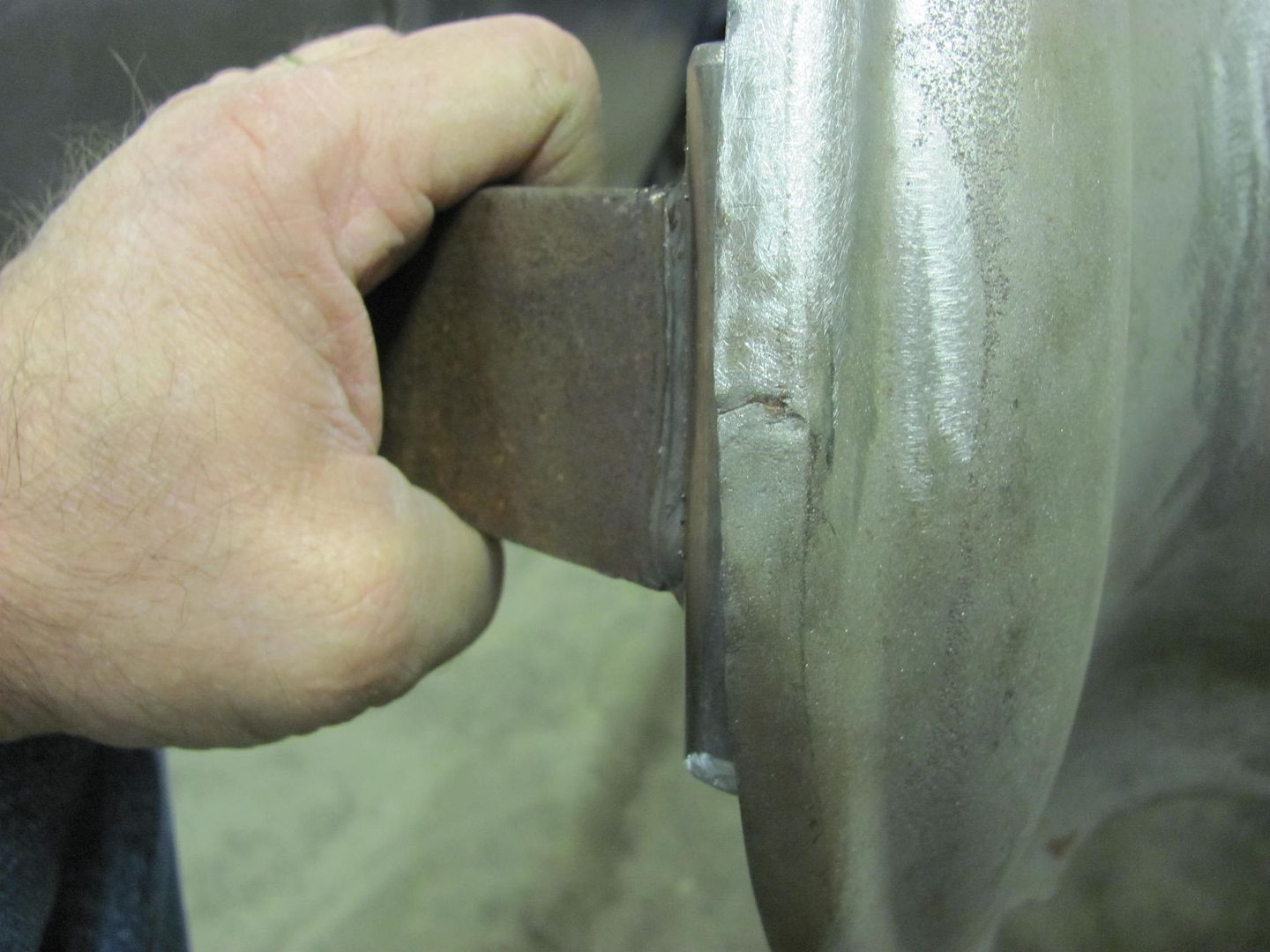
One issue with using a gap is a greater chance of blowing holes. If you attempt a weld near the edge of a panel, it will tend to burn back at the edge as there is not as much heat sink and support for the weld puddle as when there is metal completely surrounding it. By the same token, using a gap increases this same possibility. As a workaround to issues like this, rather than reducing the heat and risking lack of weld penetration, here is a patch I installed where extra metal was left protruding out. This helps to eliminate the burn back at the edge of the panel, and the excess is trimmed off after dressing the welds.
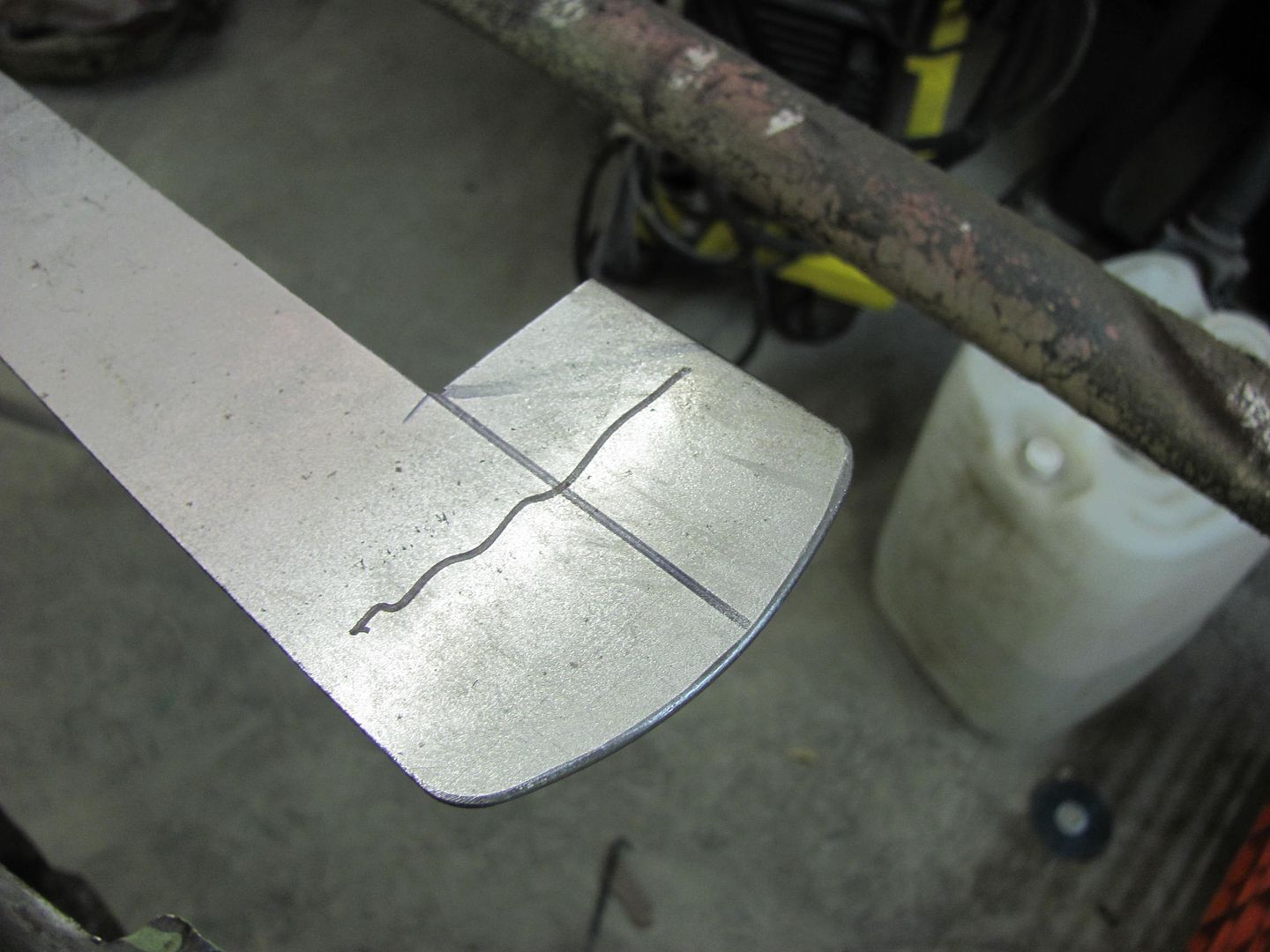
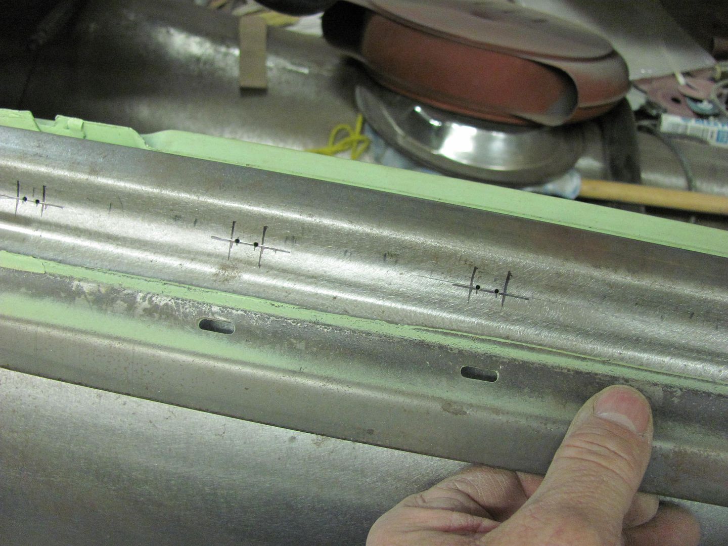
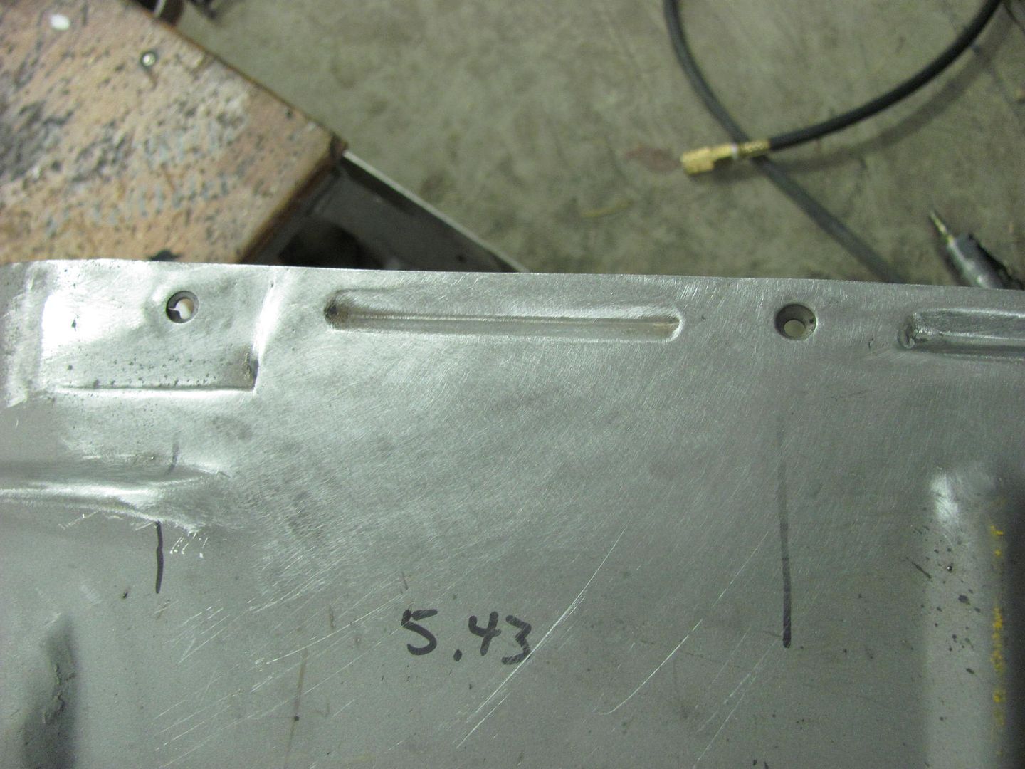
A replacement was made and marked out on the inner fender..
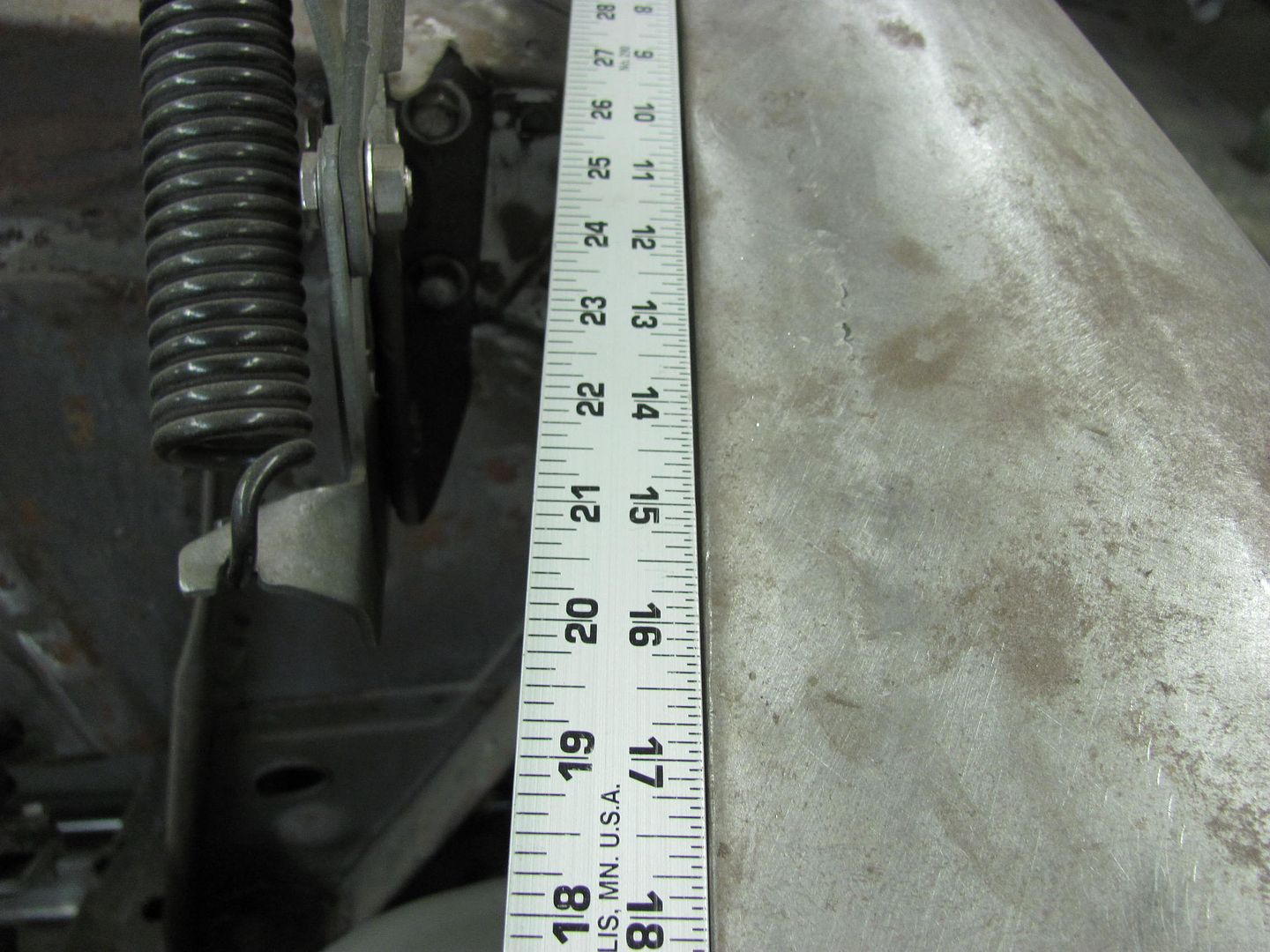
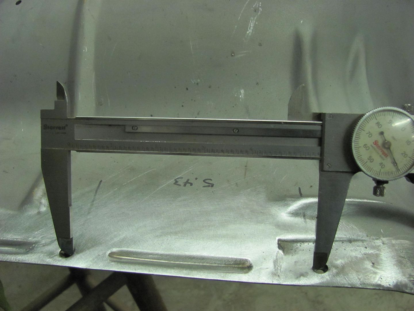
Took a reference measurement to insure any shrinking effects were properly planished out...
Ice pick works well in marking the cutout pattern...
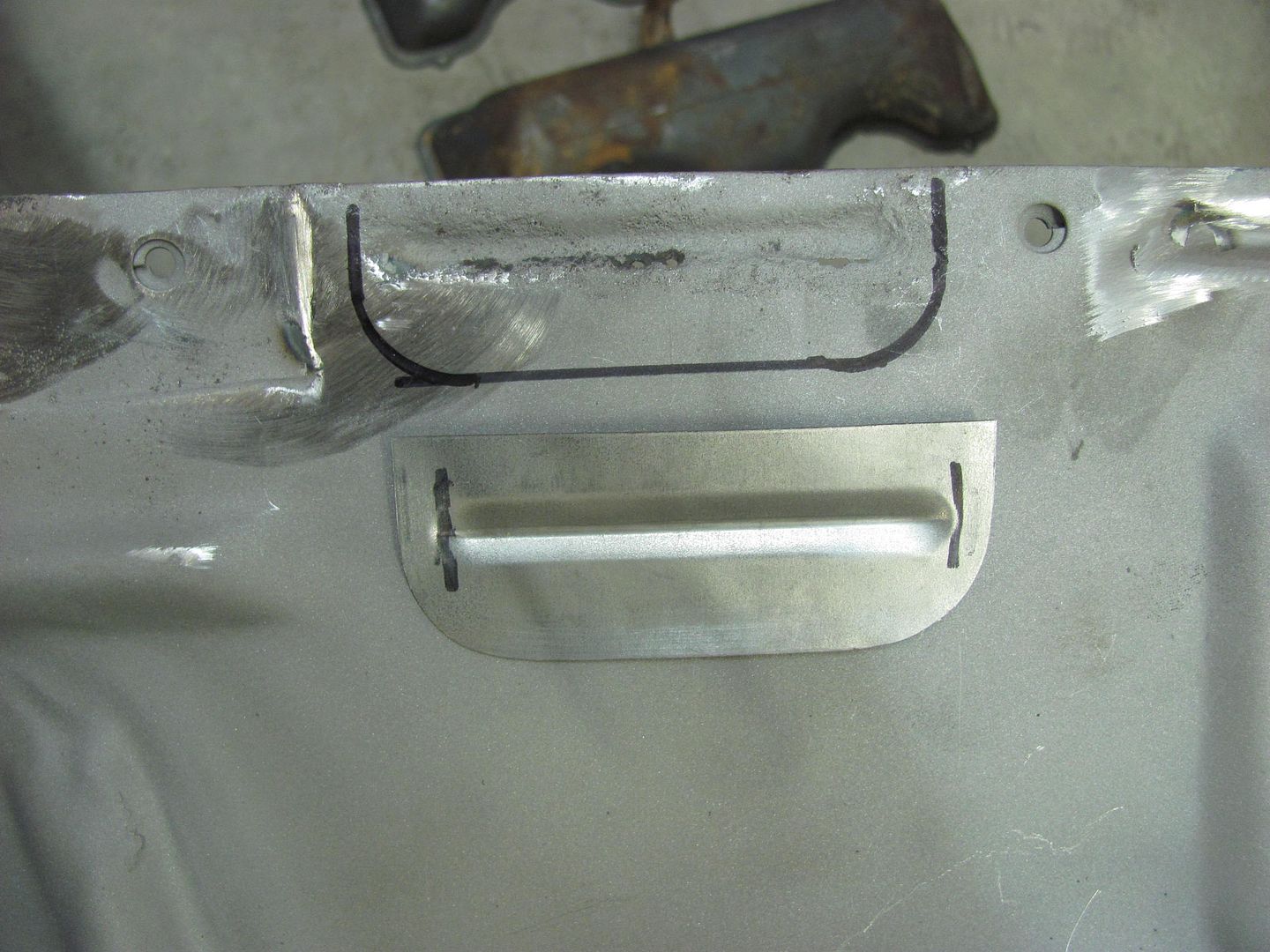
Trimmed and fitted
Tacked in place...
Rear side
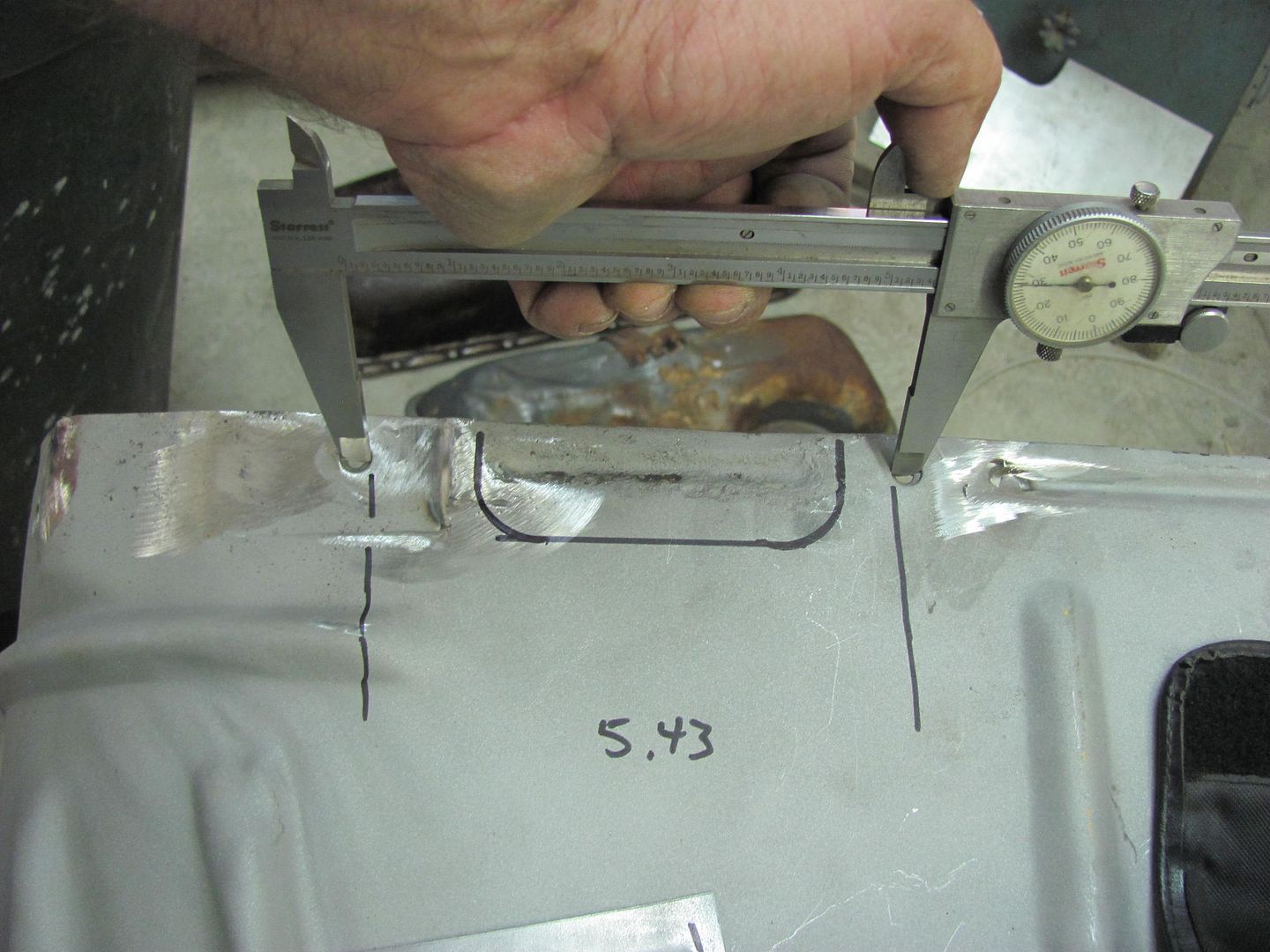
After planishing and dressing the welds, re-checking the reference measurement....
Next, gaps give a much greater chance of panel movement. Weld on either side of a set of **** weld clamps and see how much movement you see. If you have a low crown panel such as a quarter panel, with a seam horizontally through the middle, any welds along through that seam will pull at the surrounding metal, risking a loose oil can as the panel looses some of it's shape. With the panels tightly together, there is less risk of this, and your planishing is limited to a stretch to overcome any shrinking effect. With a gap and any panel movement, now your planishing is trying to overcome shrinking, and also to overcome any movement to restore proper crown to the panel. So where you did not have any "visible" rippling/dimpling, no doubt some shrinking still occurred where you did lose some crown in the panel.
In the interest of self improvement, where most people use the MIG as it is a "point and shoot" type device, Using TIG or O/A gas welding with filler rod would give a softer joint with less grinding. Both these are less tolerant of gaps in the panel as you are relying on yourself for the "feed speed". The ultimate goal would be a no-fill fusion weld with TIG or O/A. Both these methods require an absolute tight joint or there will be burn back. By using tight gaps, you are gearing your methods to more consistency where a transition to one of those preferred methods will be a more seamless one. Through consistency and constant improvement we better attain a panel that doesn't require as much/any filler, and the processes to attain said results start to become second nature (OCD of sorts). It's at this point where someone is getting to a skill level where they can metal finish a panel where no/minimal filler is needed at all. I hope to get there one day myself.
Thanks for all your help to this point.
It sounds more than anything that you just need to work on your hammer and dolly methods to eliminate the panel deflection. It also may be a case of too much planishing. We're primarily only trying to negate the shrinking effect at the point of initial planishing. Don't try to do it all right at the starting gate.
Last edited:
wbrian63
Well-known member
It sounds more than anything that you just need to work on your hammer and dolly methods to eliminate the panel deflection. It also may be a case of too much planishing. We're primarily only trying to negate the shrinking effect at the point of initial planishing. Don't try to do it all right at the starting gate.
No doubt about it. The best tools in the world won't compensate for lack of technique.
I much prefer the no-gap method of assembly, and I'll work on my planishing technique.
I'll let you know how it goes with the thicker wire.
A couple of questions about planishing -
1) How much is enough? As I understand the concept, a weld is effectively a "dollop" of filler wire that melds with the surrounding metal at high temperatures. When the metal cools, it shrinks slightly. With a hammer and dolly, we're attempting to flatten the weld, which will cause it to expand and compensate for the shrinking.
So how do you know when enough is enough?
2) What do you do when you can't get to the back of the panel with a dolly? In some of the spots I'm working on, there's little or no access. In others, it's simply not possible for me to reach around to the other side of the panel to hold the dolly. I work alone, so an extra set of hand's isn't an option.
Thanks for all your help to this point.
Responses in blue
A couple of questions about planishing -
1) How much is enough? As I understand the concept, a weld is effectively a "dollop" of filler wire that melds with the surrounding metal at high temperatures. When the metal cools, it shrinks slightly. With a hammer and dolly, we're attempting to flatten the weld, which will cause it to expand and compensate for the shrinking.
So how do you know when enough is enough?
This is something that will vary from one person to the next or job to job based on panel thickness, wire used, technique, hammer force, weld dot size, etc. So my suggestion it to weld a test piece and see how it works for you. I've written this before but I've come to realize the sizes I gave earlier aren't as quick to show the changes, so we'll change it up a bit and see how it works. I'll preface this by saying that this "test subject" serves as a guideline only, and is intended to help you see the effects of shrinking and how the planishing counteracts those effects, more so than establishing a hard and fast measured amount. It is not intended to be the end all-be all of how much, but it should get you in the ballpark of a measured amount to keep the panel in relatively good shape with minimal warping effects during the initial planishing efforts.
For your planishing test subject, you need two sheet metal strips about 3/4" wide by about 12" long. These should be the exact thickness of what you will be using on your car/truck, and will be tacked together on the long edge. They will work best if you have a shear, as you can cut a piece 1-1/2" x 12 and then shear it through the middle for a perfect seam. Thinner pieces cut on the shear will tend to curl so you may need to flatten afterward. For you to see the effects of the shrinking and then the planishing, it works best to be a perfect cut through the middle, so using a shear will help tremendously.
Next, the process and specifically amount of planishing needed is going to be directly related to weld dot size and/or wire type/softness, etc.
Now that you have a fresh cut test piece, take your two pieces and align together TIGHTLY along the long sheared cuts and tack the seam at about 1/2" in from one end. (my samples in these pictures are not sized as indicated above, so ignore that part)

DO NOT PLANISH at this point. Go another 1/2" and add another tack. Is there any change in panels positioning? Go another 1/2" and add another tack. What we are trying to do with this process is to monitor how much shrink is occurring. The first tack should "anchor" the two panels together at the end. With the panels tight together, each subsequent weld tack will start to shrink in both pulling the panels together and also shrinking in overall length along the weld. In effect, this will start to manipulate the panels where the individual pieces on the un-welded end try to overlap each other. So If you haven't seen this happen, keep welding dots at 1/2" spacing until it does happen.
Now that you see these panels overlapping, the next phase is to see how much planishing it takes to "undo" the overlap. Start at your anchor tack, and hammer and dolly once.
Go to each subsequent dot and apply the same hammer and dolly in the same approximate force. The flat should be similar in size, but I'd gauge your effort more on hammer force than size of the flats. When you get to the end, check the overlap to see if it still interferes with adjacent panel fitment at the un-tacked end. If it still overlaps, start at the beginning, repeat the planishing of one dot at a time with only one hit per weld, monitoring overlap. When your panel overlap issue has been resolved, your weld dot planishing effort should be the number of hammer strikes per weld dot that it took to resolve the overlap, using approximately same striking force. This assumes your weld dots don't mysteriously grow in size to add the need for more planishing, so again the importance of OCD consistency. This planishing effort will not be the end of the metal bumping to your panel ie: once you get welding in your patch panel/hood scoop/etc. It is the initial needed to help relieve the shrinking effects so the differing forces will relax a bit. What we did in striking one dot once and then move to the next is only for test purposes to identify the number of strikes you needed per weld dot. After this initial planishing, any remaining planishing needed will be based on what the panel looks and feels like, high spots, low spots, etc after welding, initial planishing, weld dot grinding, and panel reading is completed.
Now that you have completed this, just for the heck of it, go to the first anchor dot, and start planishing it and it alone. Keep repeating until you see the adjacent ends start to separate as the weld dot is being stretched. Look at how wide the gap is. This approximates the amount of extra effort needed to overcome the shrinking and panel movement that happens when you leave a gap that size in the panel. It also demonstrates the differing planishing efforts that will be needed for inaccurate and inconsistent gaps. For any inconsistencies in your weld seam (gap size, weld dot size, etc), keeping track of what, where, and how much is the tricky part, and adds to the challenge of sorting out the panel where it can be finished with minimal filler. Some may be OK in using thick filler, but it doesn't take that much effort to become more consistent in your processes to eliminate such a need for excess filler. This importance of consistency is in all the processes, starting with tight gaps at fit up. Everything that you can do to keep consistency throughout from start to finish only makes the planishing efforts more consistent throughout, lessening the need to keep track of the errant what, where, and how much.
Last edited:
Continued, responses in blue....
Glad to help!2) What do you do when you can't get to the back of the panel with a dolly? In some of the spots I'm working on, there's little or no access. In others, it's simply not possible for me to reach around to the other side of the panel to hold the dolly. I work alone, so an extra set of hand's isn't an option.
There are a few different considerations, mainly in locating weld seams to minimize the shrinking effects, especially on low crown panels such as the quarter panel. In most cases, a seam horizontally through the middle of a quarter panel is just asking for trouble as there is little shape (strength) in the panel to resist any movement/distortion from the shrinking, and why a weld here normally results in a severely caved in valley. (given no planishing to counteract the shrinking). For the most part one would put the weld up as high as possible, as most quarters have enough shape toward the top where the quarter slopes inward to help resist movement and distortion. It also puts the seam up where most if not all is better accessible for planishing. That is the normal scenario.
In other cases, the panel may be blocked by an inner wheelwell or other structure that prevents/discourages planishing the weld. In this case, one can be creative in making a dolly on a stick, say a piece of steel flat bar that would fit in the void, welded to a pipe to allow better reach (don't forget the dolly face should match panel contour without corners touching). I've also employed the assistance of my nephew in remote cases where his youth permitted more of a contortionist approach over what my body refuses to do anymore. This is also why it is important to planish those weld dots individually, and then grind them out of the way, front and back. This way two people can better work together on either side of a panel to planish out the welds, and find the correct weld dots in doing so. Next, you have the option of removing the outer wheelwell to better address an exterior panel that everyone will see, and then replace the wheelwell after you are satisfied with the metal bumping and finish work on the quarter.
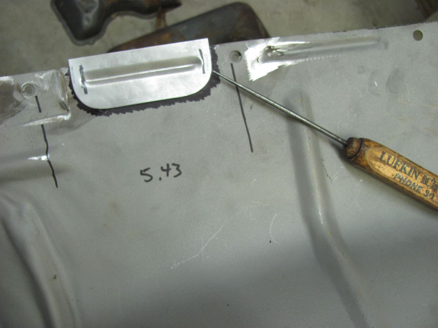
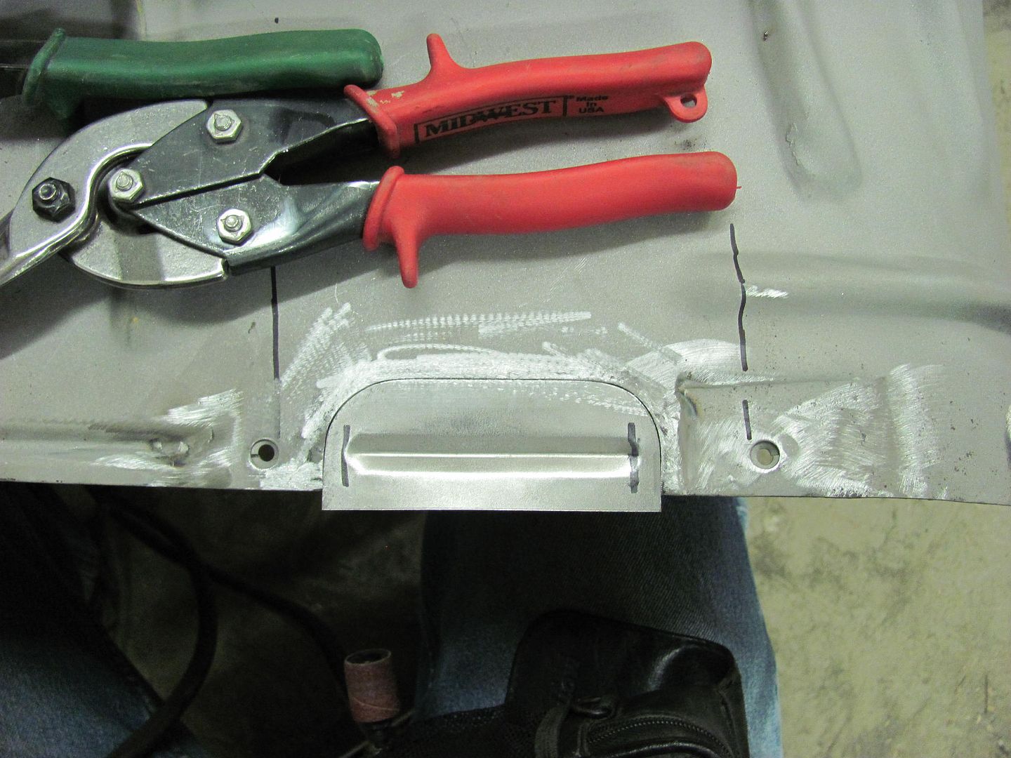
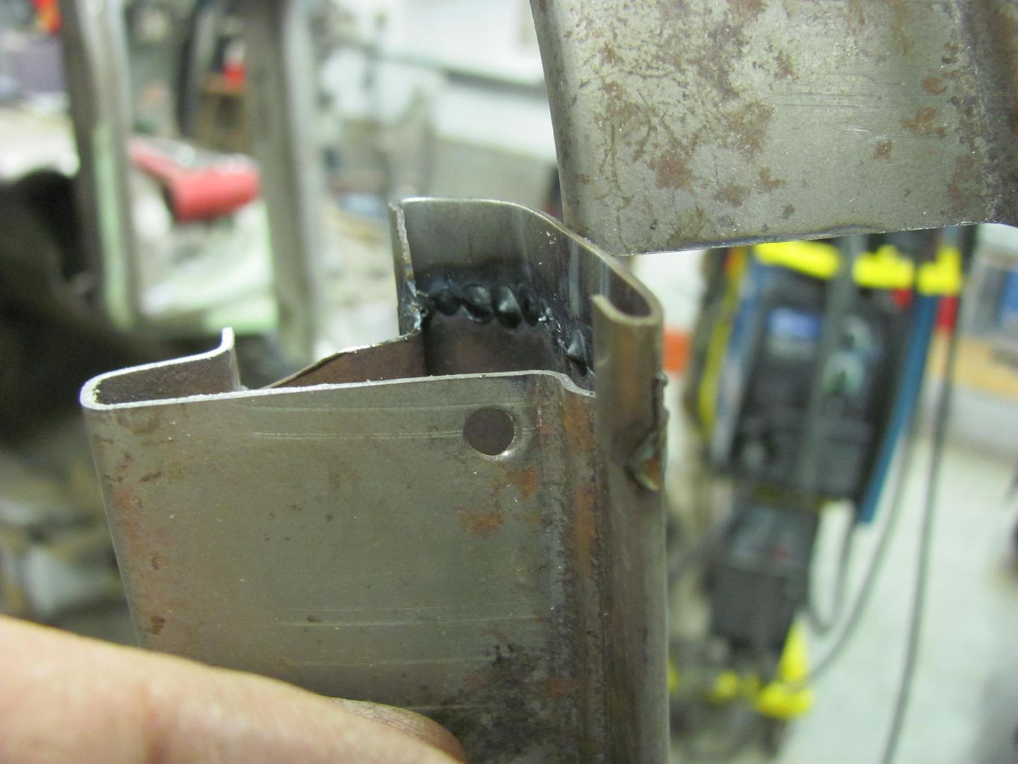
Next, strategic weld placement can help to minimize shrinking effects and thus the need for planishing... Here is the start of a fabrication I did to repair a lift gate with pin hole issues.

As far as panel fitment when it went together, the joints also were about as tight as you can get. This is important as it minimizes any panel movement, another thing that will help is consistency in your welds and overlap spacing, as it is INCONSISTENCY that is a major cause of panel deformation.
As this was the last panel installed on this repair, I couldn't get to the back side for planishing in this panel. Here, as you'll see, weld location helps to minimize the effects of shrinking.
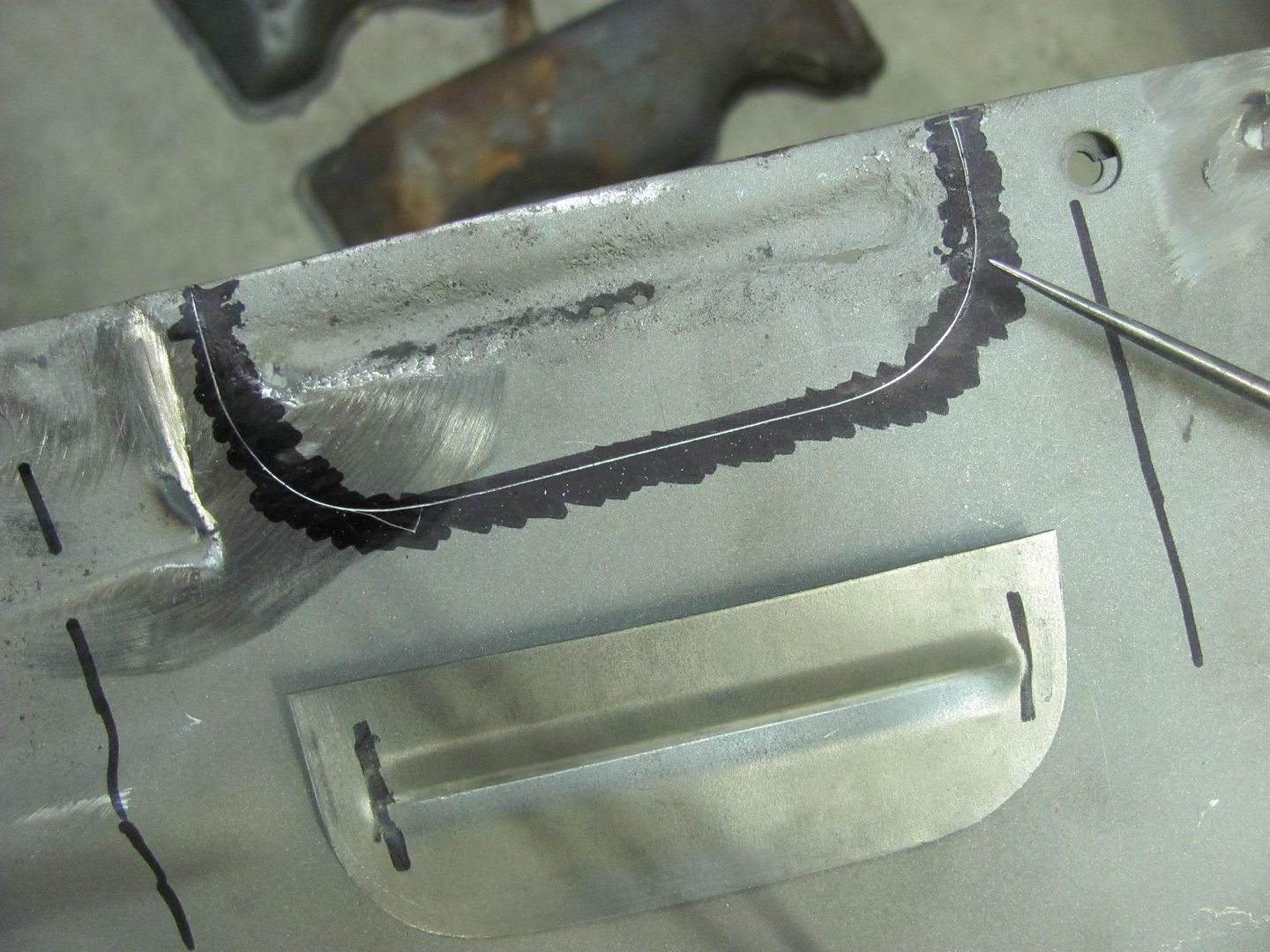
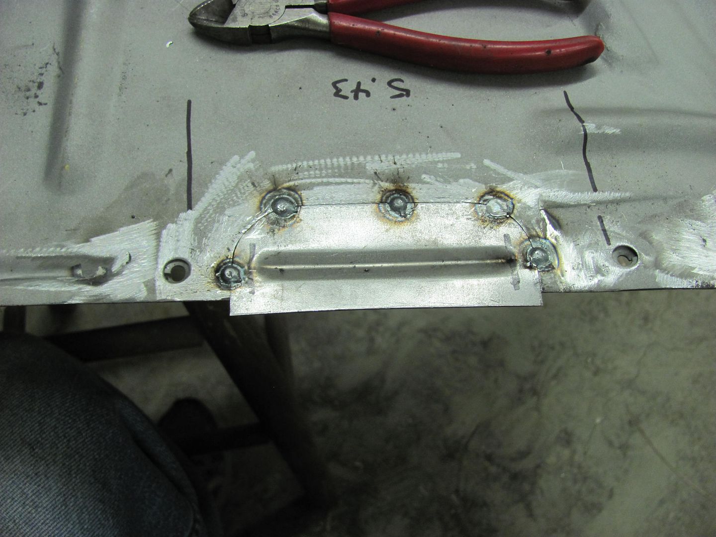
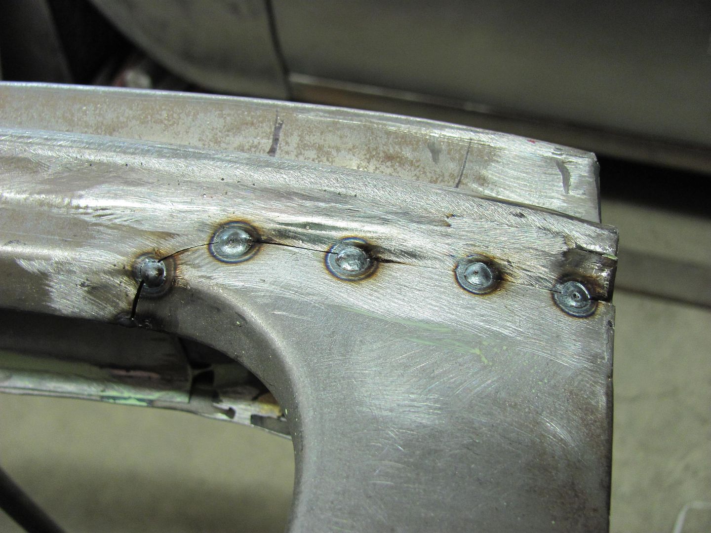
Welds in process....
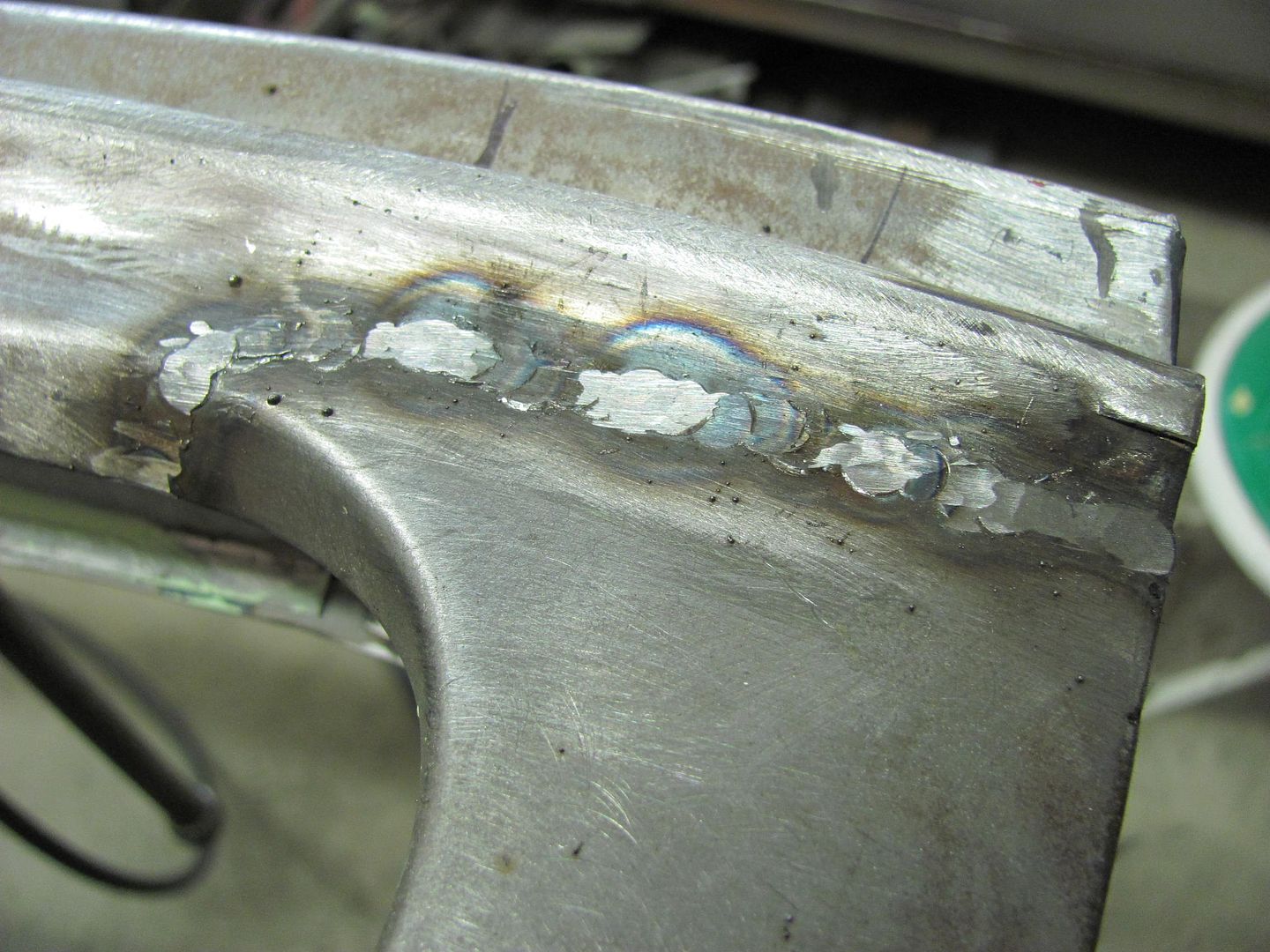
After welds were dressed.....
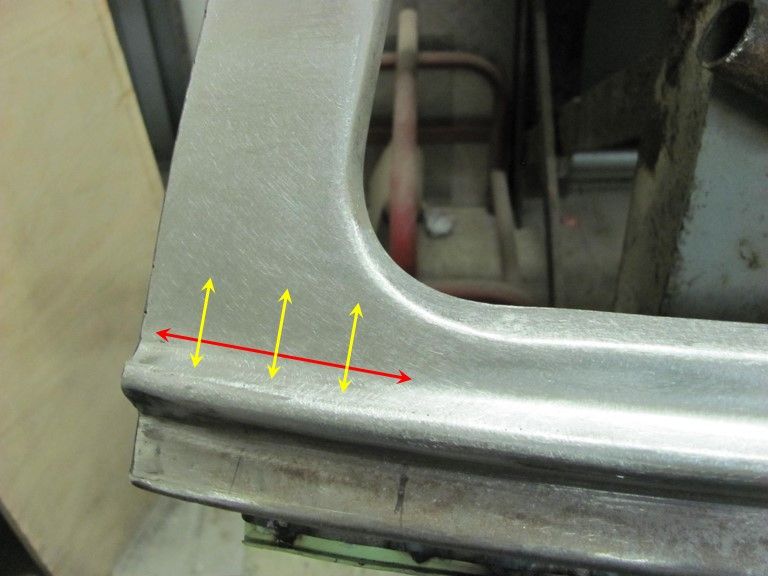
Looking at the weld area, one would expect shrinking issues along the horizontal crown where the length of the weld (red arrow) would pull down into a valley, or toward the inside of the lift gate. Now looking at the reverse crown (vertical) as indicated by the yellow arrows, shrinking issues there will have a tendency to pull the weld outward. So in essence, the weld placement has been located such that these shrinking effects will help to counteract each other, for a virtually filler free repair. The results would been different if the panel's crowns both had been going the same direction.
So to summarize, if you have a choice in location for the weld, picking an area that has horizontal crown and vertical crown going in opposite directions will help to minimize the adverse effects on the panel from the shrinking issues. For locating welds in low crown panels, higher on the panel usually has more crown to help hold shape, or locating parallel to a prominent body panel crease will help to hold the shape.
Thanks for all your help to this point.
Last edited:
Ohmthis
Well-known member
Robert, Im VERY thankful that you take the time to explain in great detail your technique and why you do things a certain way. You have a great gift to explain some complex notions of metal movement to where it is easily understood. All with humility as you could easily keep these "dark metal working secrets" to yourself.
[email protected]
New member
- Joined
- Feb 28, 2014
- Messages
- 2
Yes, great explanations - extremely helpful
Sent from my iPad using Tapatalk
Sent from my iPad using Tapatalk
8man
Well-known member
I too really appreciate the time you take with explanations. Thank you.
saceone
Well-known member
OP must be a shop teacher.
if you are not, well, you would make a fine teacher !!!
if you are not, well, you would make a fine teacher !!!
Thanks for a the comments!
I used to run a production shop at a former employer, which included a small machine shop and a cable fabrication shop. That included training employees and also writing work instructions, since they were in the process of getting ISO certified. So much of what you see written in my posts are from that background. I just hope that these posts help others to have success in their own projects..
Why is it when you're getting ready to mix primer you find other issues to fix?? More minor tweaks so that hopefully we can spray this afternoon...
A crack that looks to be from some previous body damage.
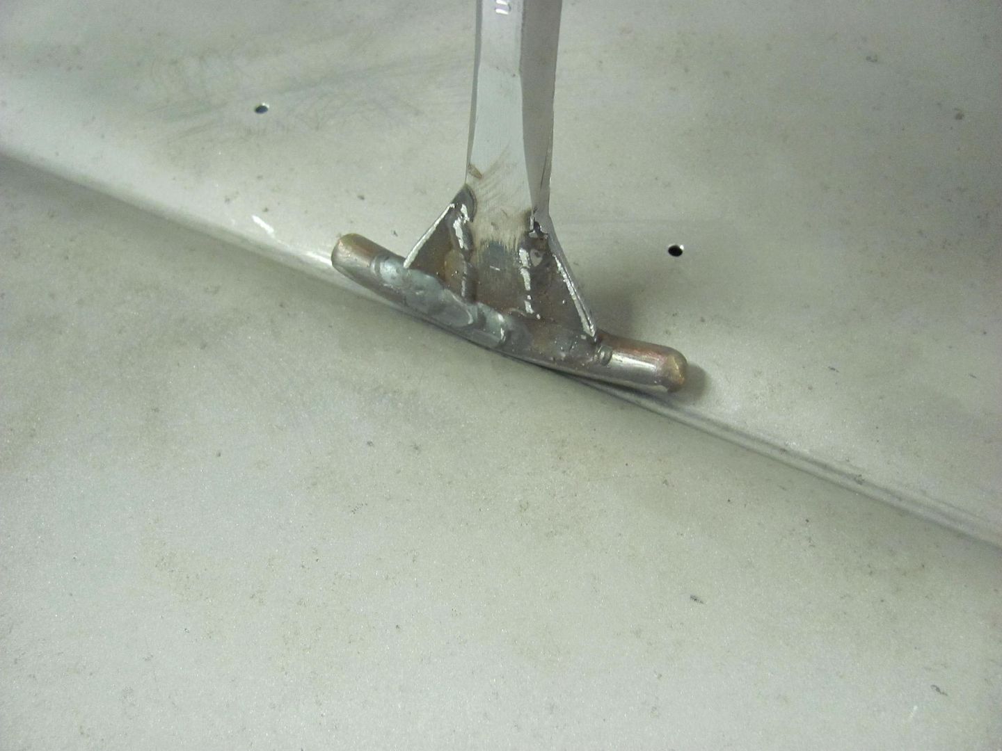
A post dolly is used to provide an off dolly effect, and the body hammer is struck on the "high" spot.
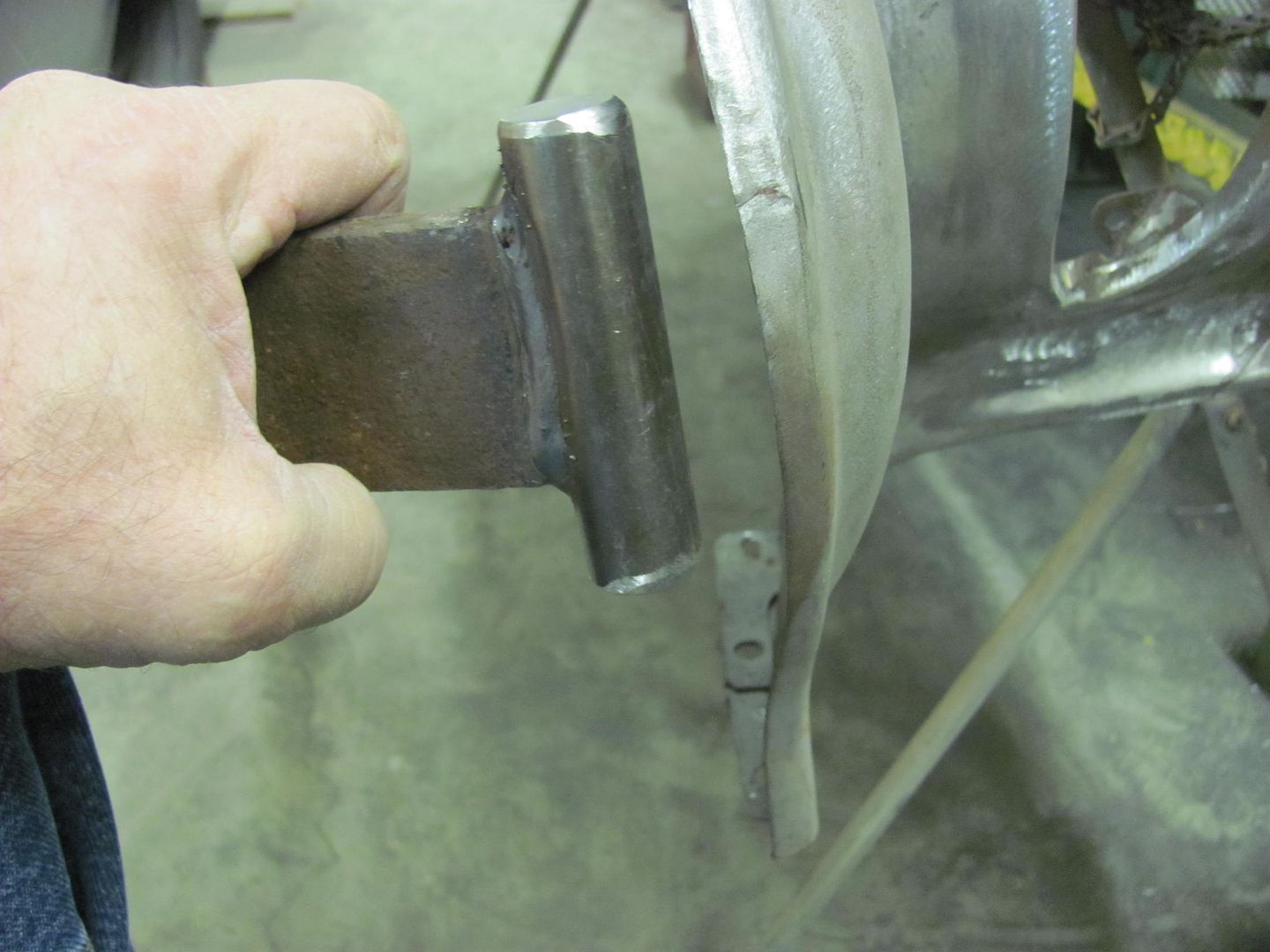
Used a copper backing since we're so close to the edge and the metal has been fatigued. Filled the crack and dressed the weld...


Then I noticed a low spot on the fender's bodyline crease...
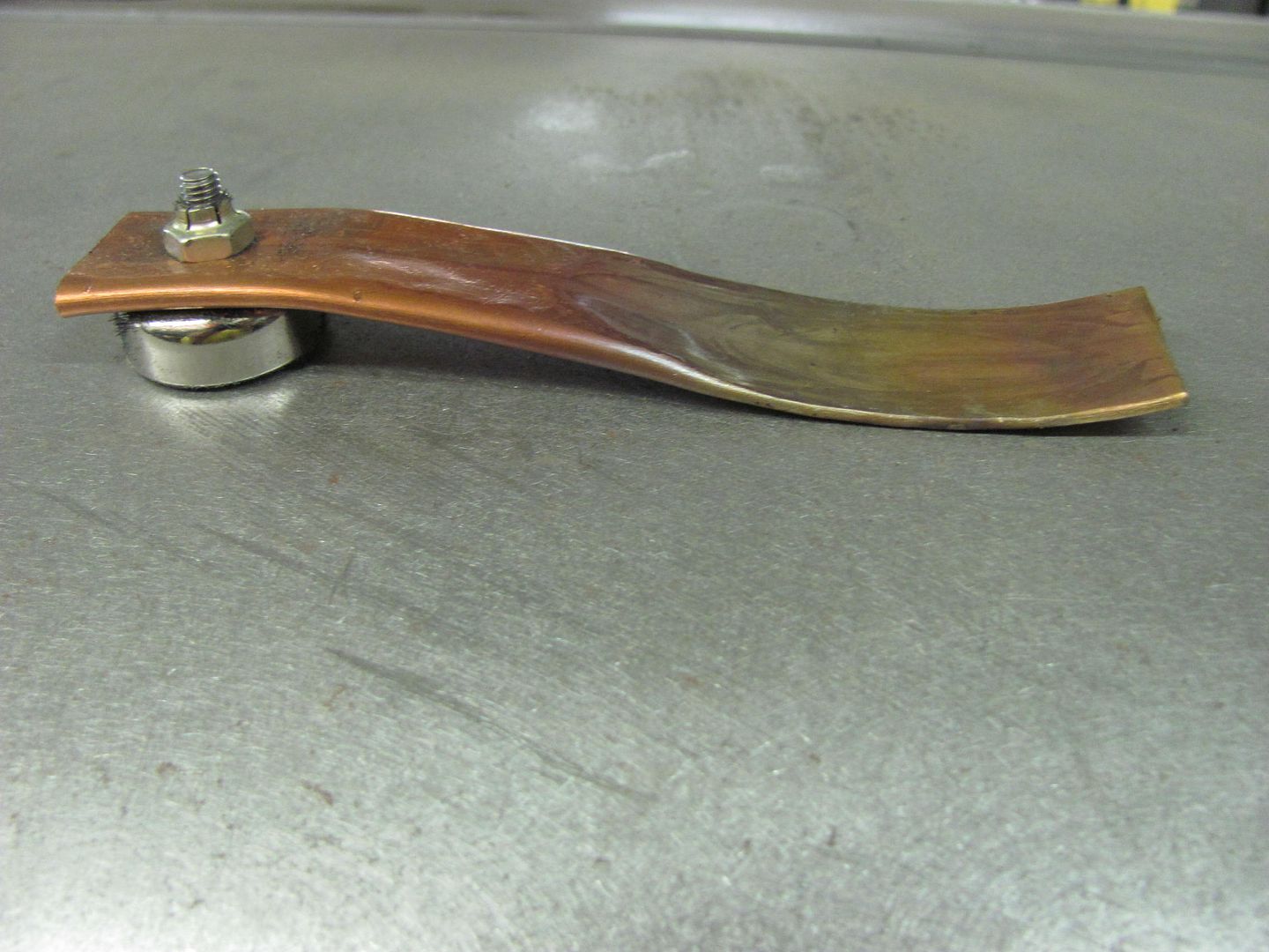
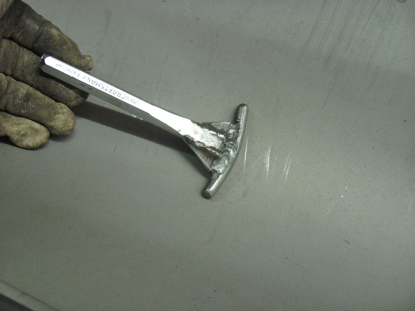
Time to lose another Craftsman chisel to become a body tool...
....the rod was heated and bent around, then finished welding.
Placed the fender on the large shot bag and used the dead blow hammer to apply the persuasive force...
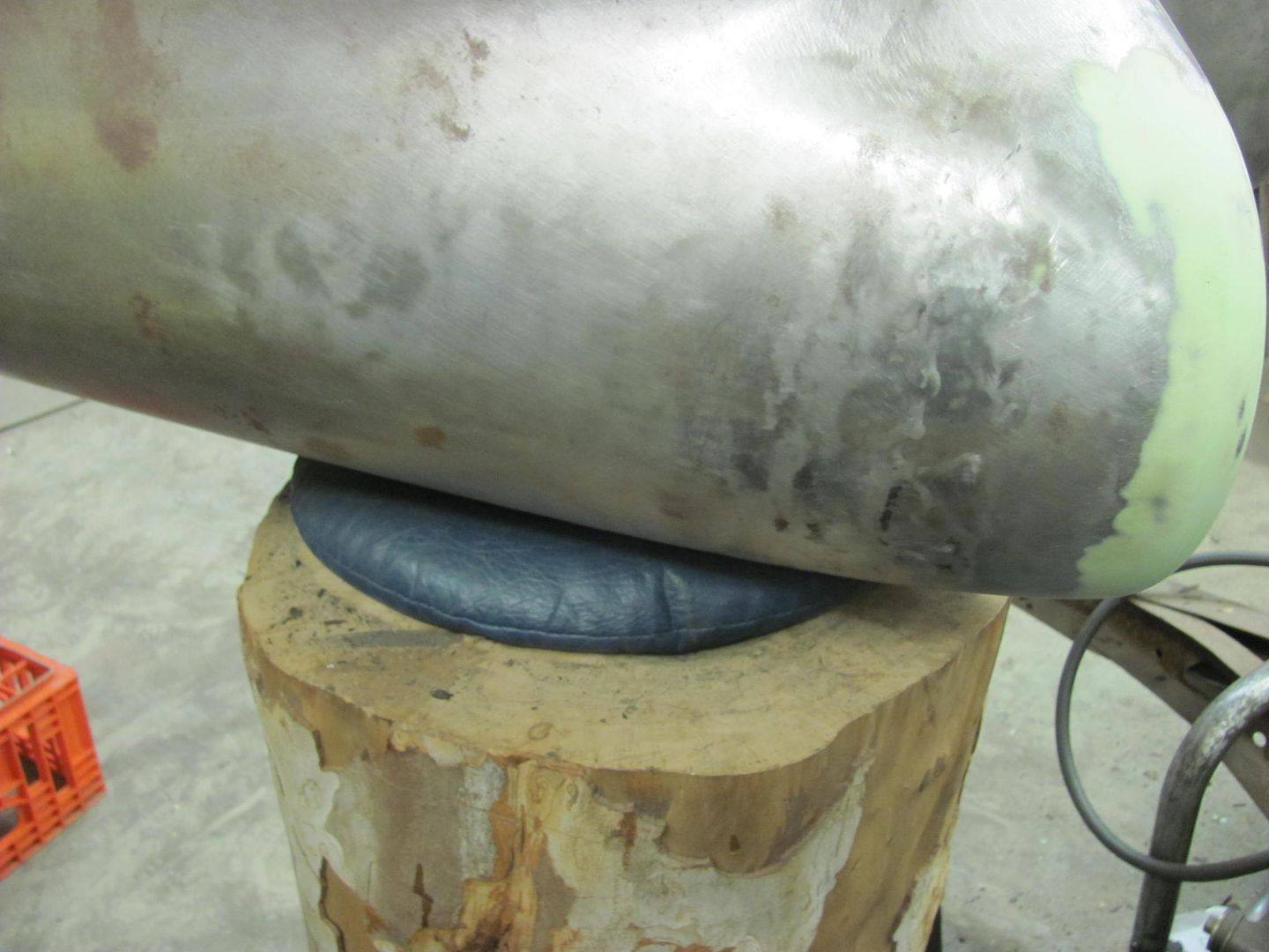
Much better with a more consistent crown across the fender..
OP must be a shop teacher.
if you are not, well, you would make a fine teacher !!!
I used to run a production shop at a former employer, which included a small machine shop and a cable fabrication shop. That included training employees and also writing work instructions, since they were in the process of getting ISO certified. So much of what you see written in my posts are from that background. I just hope that these posts help others to have success in their own projects..
Why is it when you're getting ready to mix primer you find other issues to fix?? More minor tweaks so that hopefully we can spray this afternoon...
A crack that looks to be from some previous body damage.
A post dolly is used to provide an off dolly effect, and the body hammer is struck on the "high" spot.
Used a copper backing since we're so close to the edge and the metal has been fatigued. Filled the crack and dressed the weld...
Then I noticed a low spot on the fender's bodyline crease...
Time to lose another Craftsman chisel to become a body tool...
....the rod was heated and bent around, then finished welding.
Placed the fender on the large shot bag and used the dead blow hammer to apply the persuasive force...
Much better with a more consistent crown across the fender..

yucholian
Well-known member
I noticed you use SPI epoxy a lot.
What brand of topcoat do you use and do you find SPI to be compatible with some of the major brands?
What brand of topcoat do you use and do you find SPI to be compatible with some of the major brands?
Actually I just started using it. I've used it as a sealer on some bus repairs. You should be able to use it under anything you'd like. SPI and House of Kolor are a couple of epoxies that you can indeed sand, most others are not easily sanded. SPI is a bit less expensive than H/K's epoxy.
Ohmthis
Well-known member
Robert, thanks again for you insight. One of the things that you've really shown me is that almost anything can be used as a metal working tool, PVC fittings, chisels and punches, what ever your imagination can use. Thanks again!
utahdog2003
Well-known member
awesome work!
Thanks UtahDog!
Well at the insistence of a 13 year old, we have shifted gears this evening to get a terrarium ready for a growing Albino Corn Snake. She had found this at a local auction for a good price, now we need the restraint devices to keep him in his place...

Having a couple of these from Andersen with some tears in the screen, it looks like we have plenty of stock to work with....

Trimming to size..

First side completed, screen installed....


Second cover will use two divider bars to support the heat light..

As it's getting late we'll finish this another night....
Well at the insistence of a 13 year old, we have shifted gears this evening to get a terrarium ready for a growing Albino Corn Snake. She had found this at a local auction for a good price, now we need the restraint devices to keep him in his place...
Having a couple of these from Andersen with some tears in the screen, it looks like we have plenty of stock to work with....
Trimming to size..
First side completed, screen installed....
Second cover will use two divider bars to support the heat light..
As it's getting late we'll finish this another night....
Last edited:
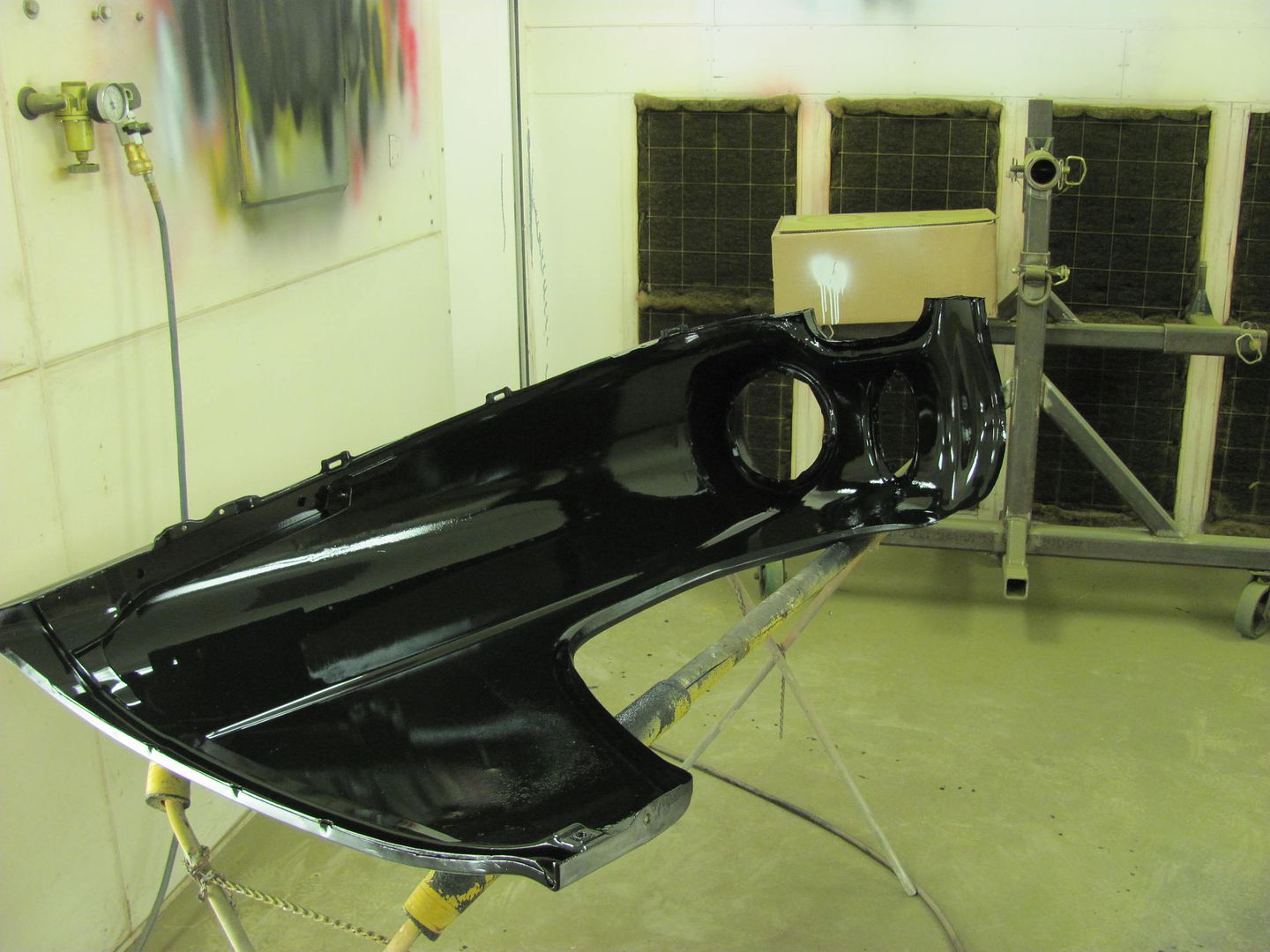
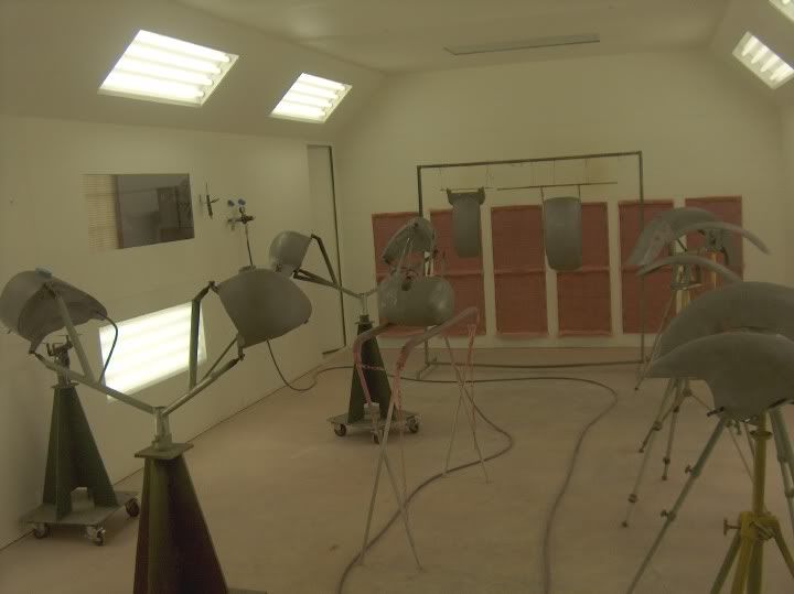
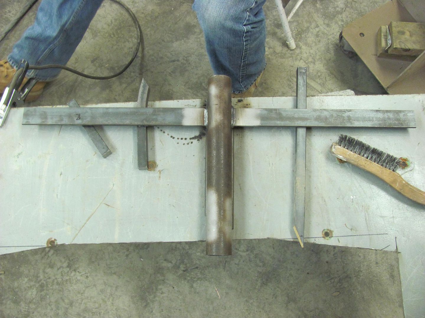
One of our projects for tonight was to make a stand to hold the doors for painting. I have some heavy duty "tripods" on casters that have a 2" ID pipe on top with a setscrew, which works well for changing out various fixtures for painting, as shown below on the left....
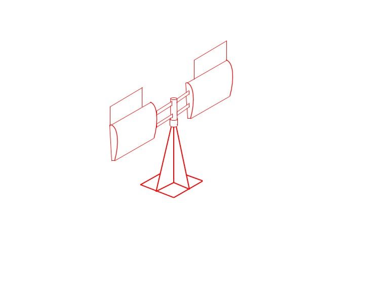
My thoughts were to make a similar "tree" to hold the doors, using the hinge mounts. Here's the prototype design...
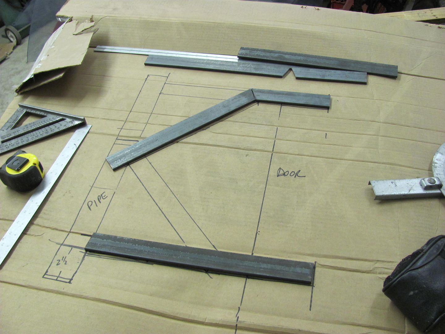
Here's our CAD layout this evening (cardboard aided design). As the flat bar is a bit cheaper than the pipe, we altered the pattern slightly...
While Kyle was working on the parts for the door "tree", I turned my attention to one of the doors that still needed some finesse. One of the problem areas on the 55 wagon is that apparently GM did not have sufficient quantity of passenger doors specific to the wagon for the assembly line, so the quick fix was to install doors from the 2 door sedan. The downside was that the rear of the door tapers off where the sedans roof starts to drop off to the back window. With the belt line trim details aligned, note what appears to be a sagging rear edge with a widening gap to the upper door opening.... Most people don't notice this detail..
For comparison, the driver's door aligns well to the trim lines...
To fix the passenger door, we plan on a sectioning and a lift kit, adding a wider patch in the B post of the door to make up the difference.
This may just work yet.. Hope so, there's a big gap there..
New section fabbed and fitted...
Bottom seam welded in place...
Yeah, this will be much better...
One seam down, one to go...
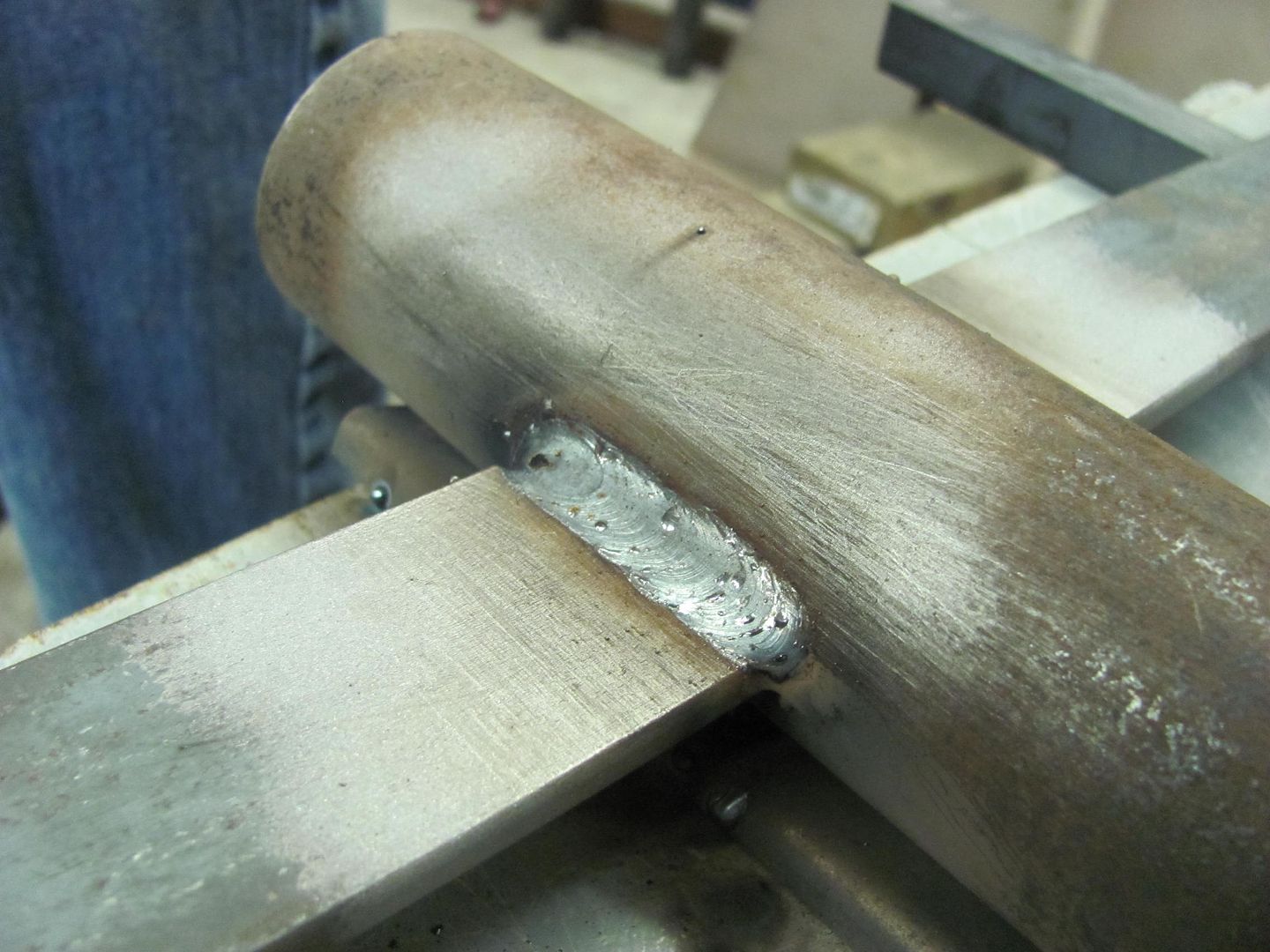
....and Kyle tackled his first welding project this evening..
until next time, Merry Christmas to all!
My thoughts were to make a similar "tree" to hold the doors, using the hinge mounts. Here's the prototype design...
Here's our CAD layout this evening (cardboard aided design). As the flat bar is a bit cheaper than the pipe, we altered the pattern slightly...
While Kyle was working on the parts for the door "tree", I turned my attention to one of the doors that still needed some finesse. One of the problem areas on the 55 wagon is that apparently GM did not have sufficient quantity of passenger doors specific to the wagon for the assembly line, so the quick fix was to install doors from the 2 door sedan. The downside was that the rear of the door tapers off where the sedans roof starts to drop off to the back window. With the belt line trim details aligned, note what appears to be a sagging rear edge with a widening gap to the upper door opening.... Most people don't notice this detail..
For comparison, the driver's door aligns well to the trim lines...
To fix the passenger door, we plan on a sectioning and a lift kit, adding a wider patch in the B post of the door to make up the difference.
This may just work yet.. Hope so, there's a big gap there..
New section fabbed and fitted...
Bottom seam welded in place...
Yeah, this will be much better...
One seam down, one to go...
....and Kyle tackled his first welding project this evening..
until next time, Merry Christmas to all!
Last edited: