stinkity stoink
Well-known member
I vote round

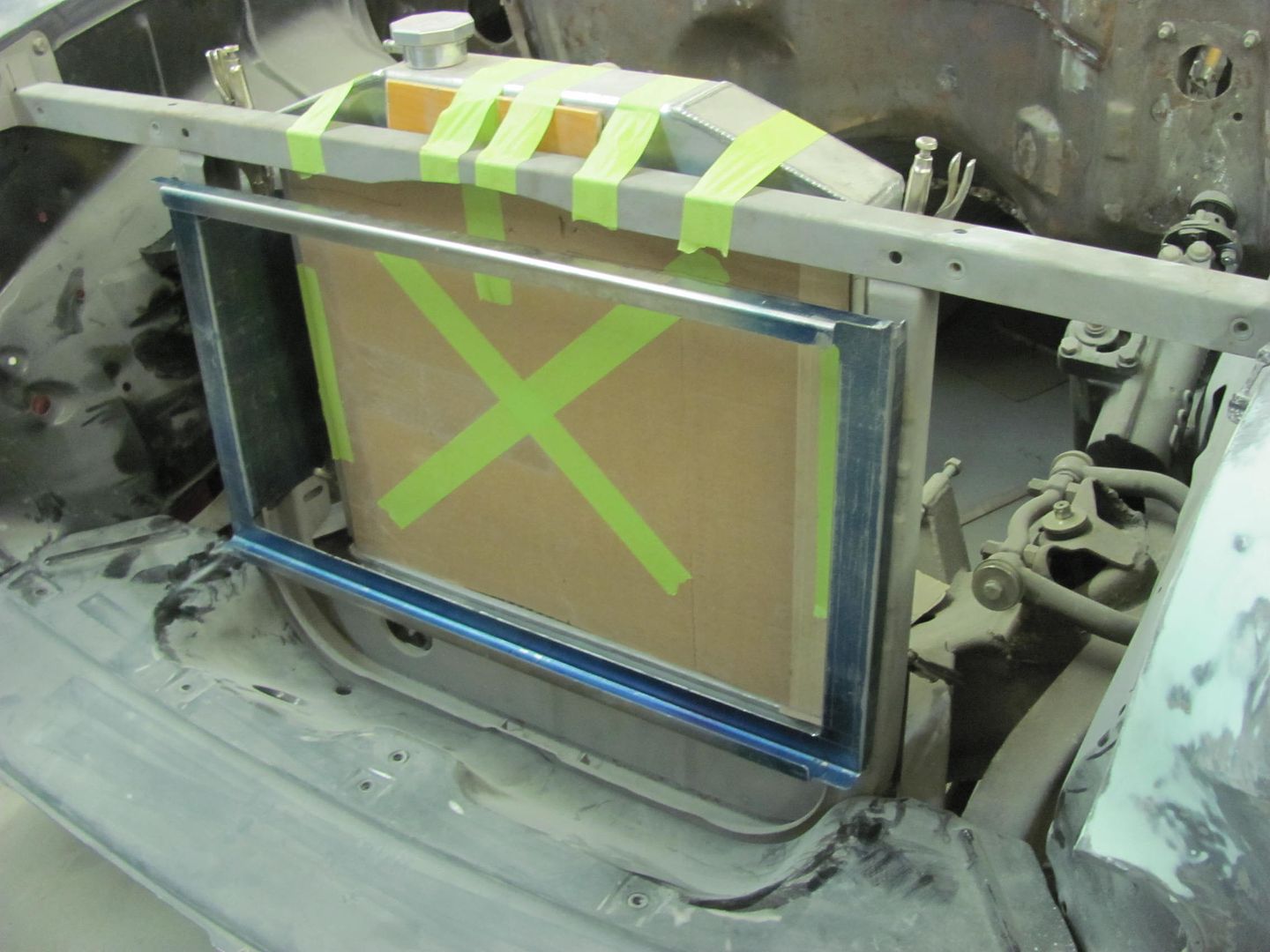
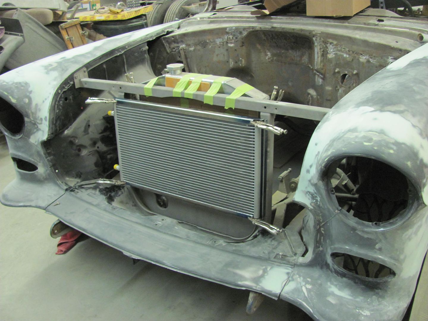
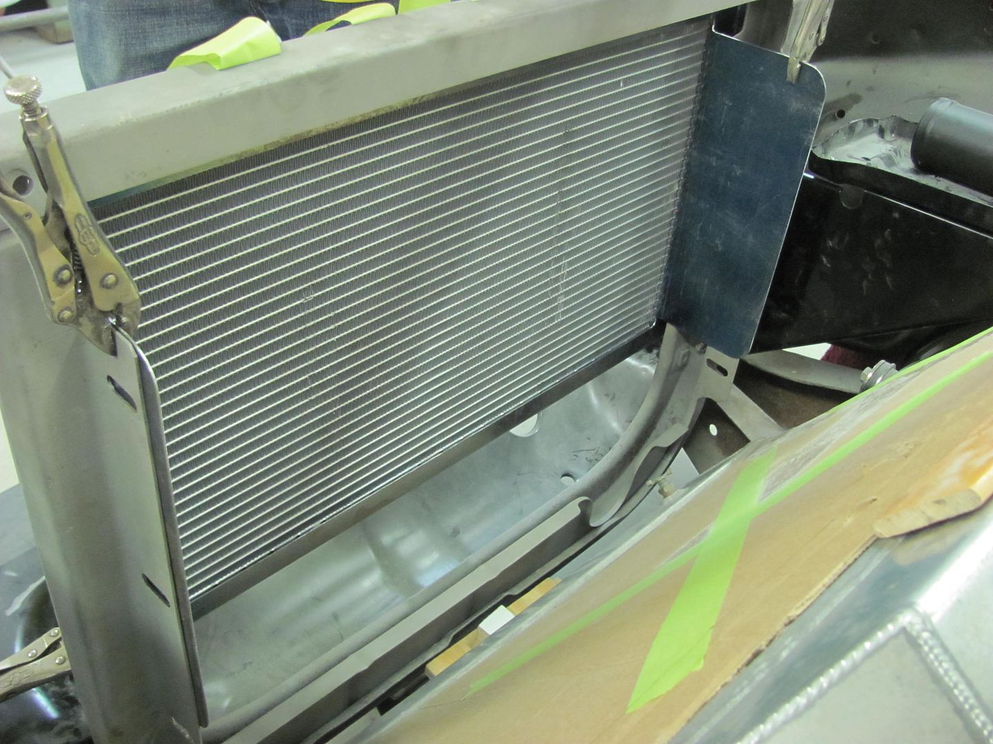
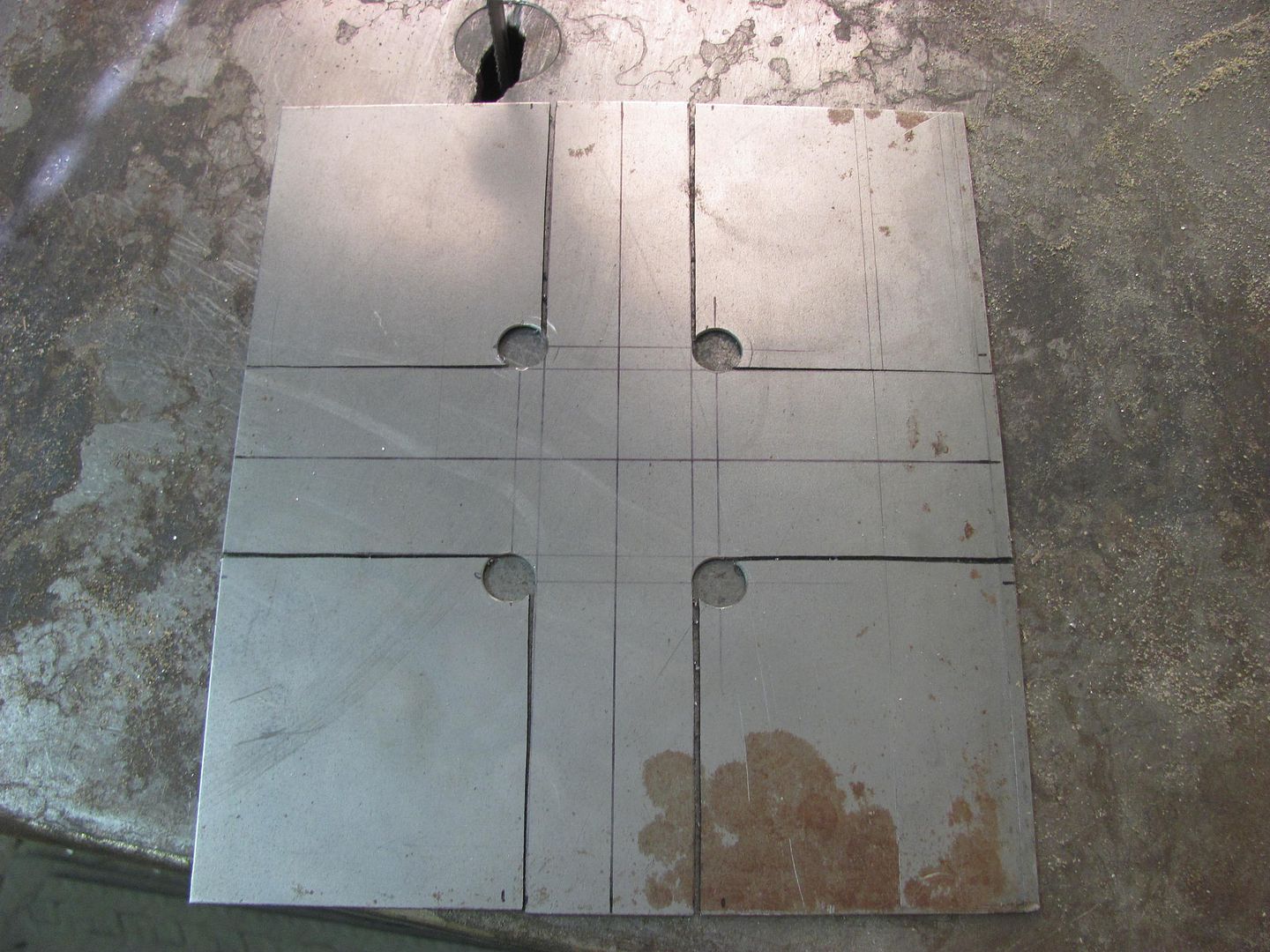
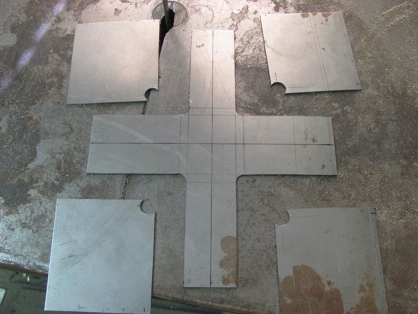
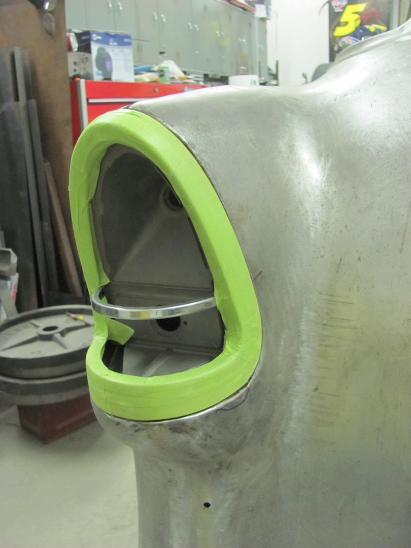
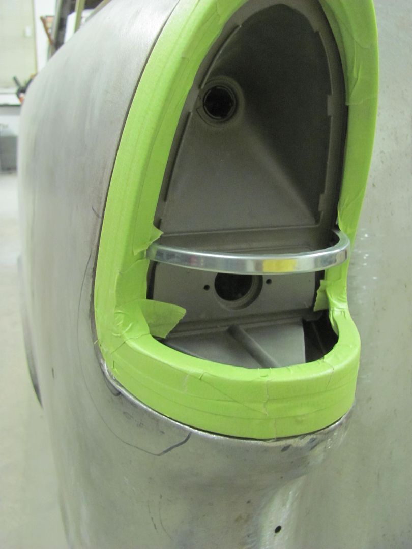
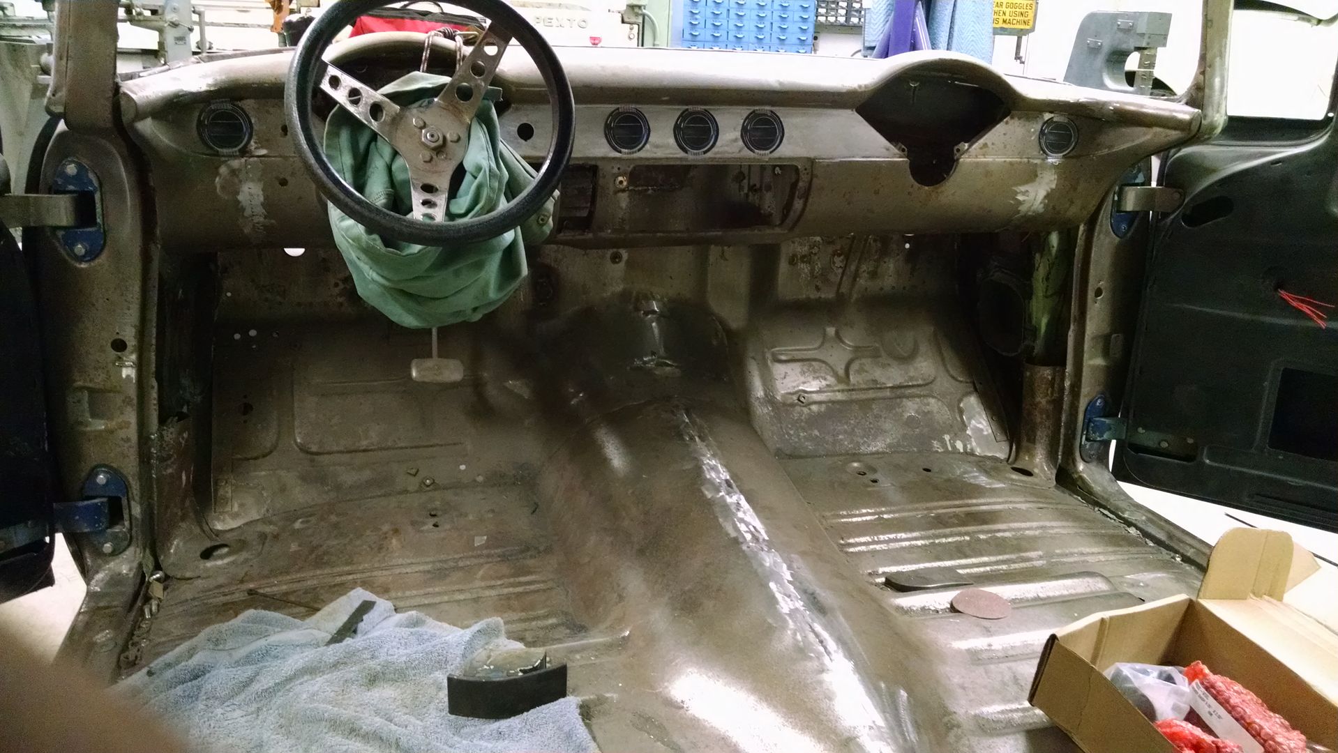
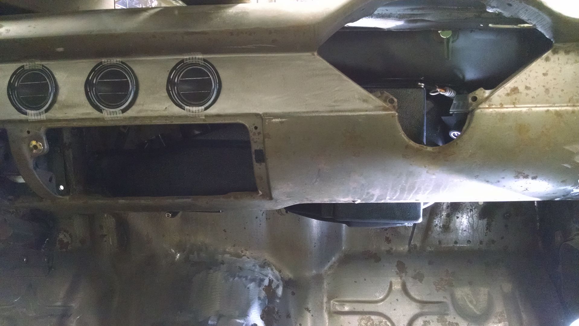
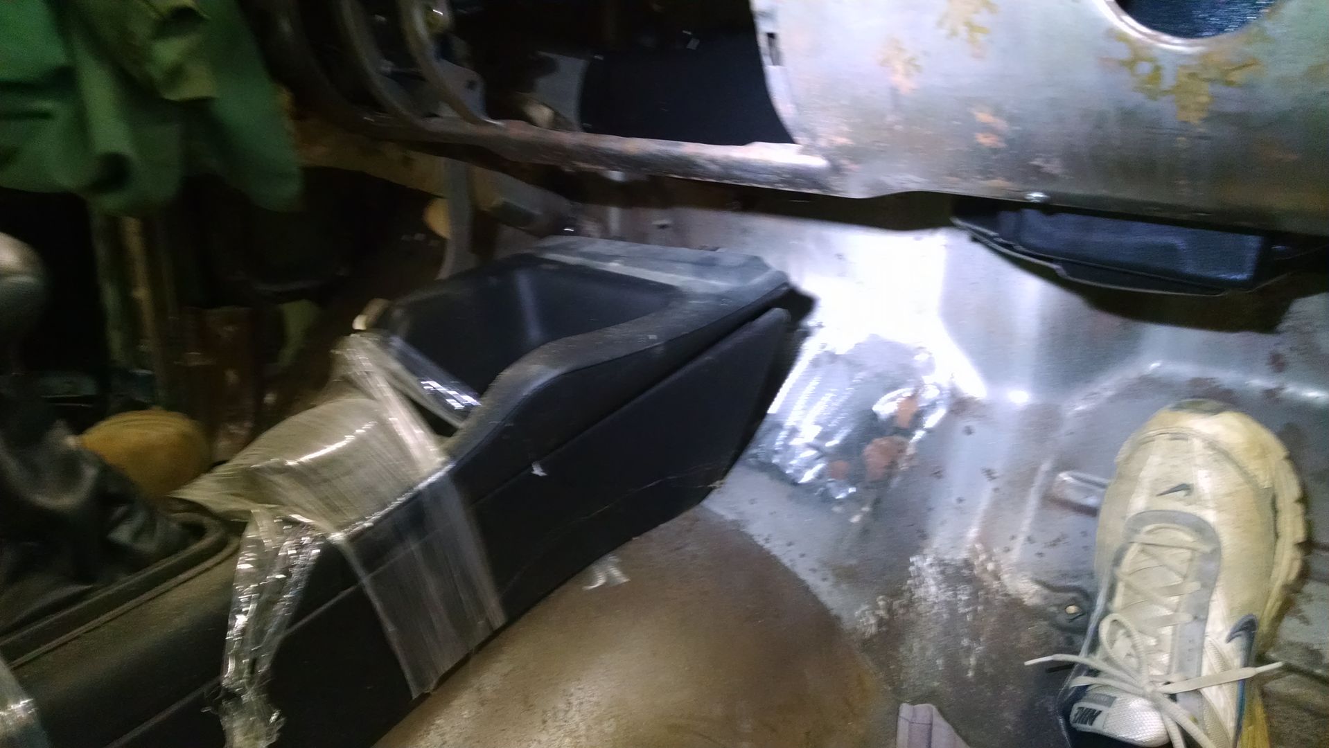
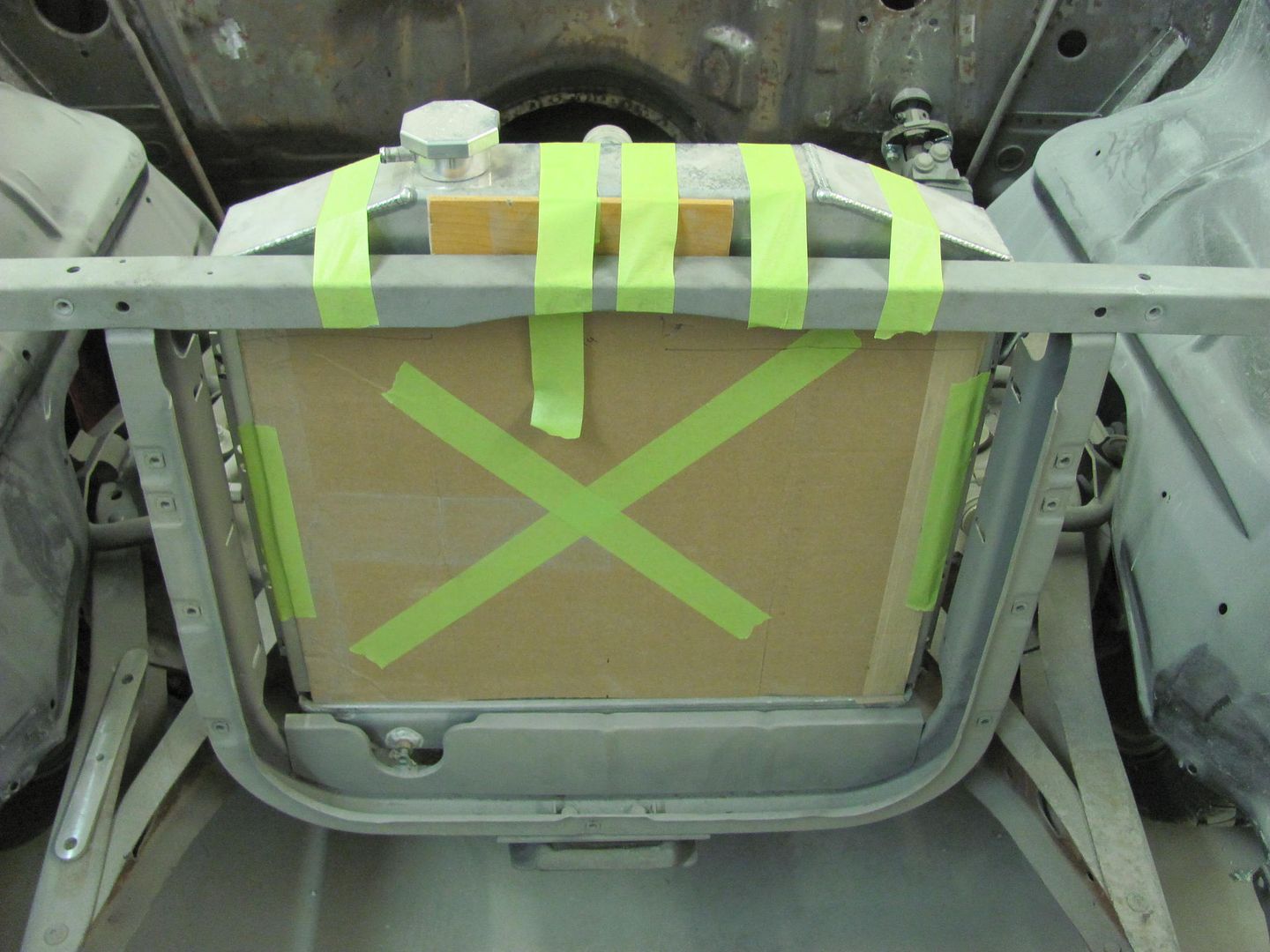
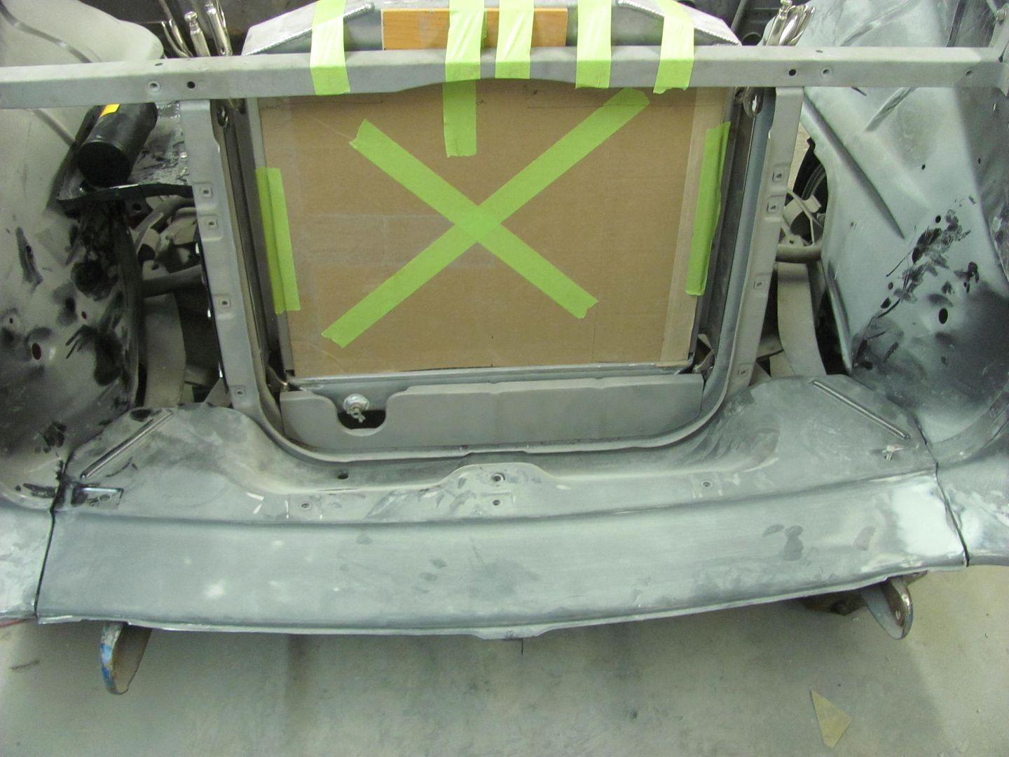
Those are pretty big rectangles. What about smaller ones, like those used in '69-77 Corvettes? You could probably fit three in the center and another two in the sides.Next, we got our AC vent samples in.. Here is the test fit with tape... Only have two of the round ones to show, but if we go with these there will be three in a row here in the center of the dash.
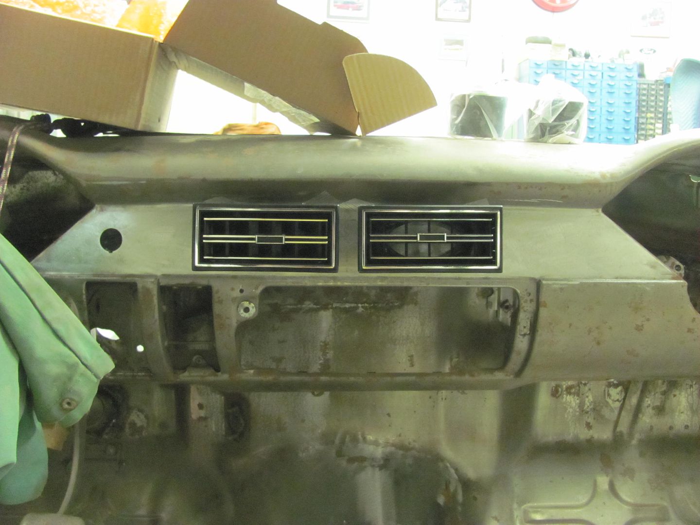
Any thoughts on the vents now with them mocked up?


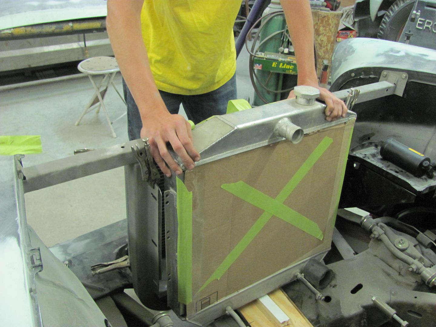
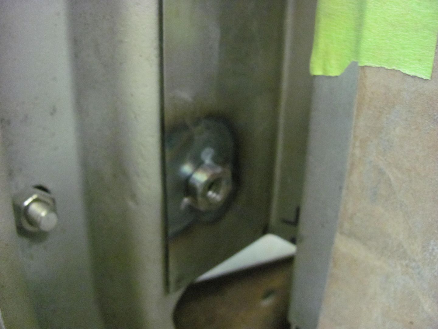
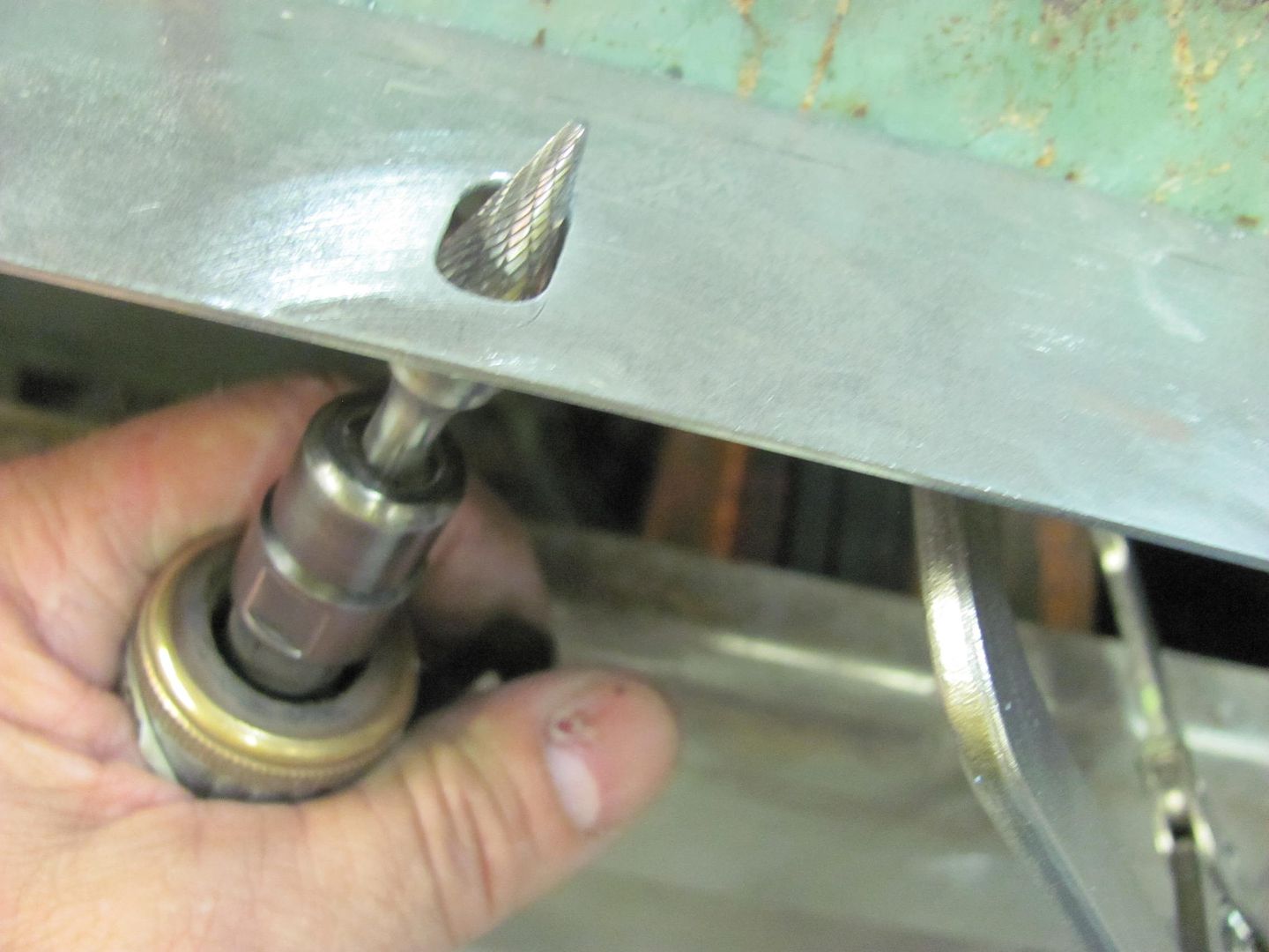
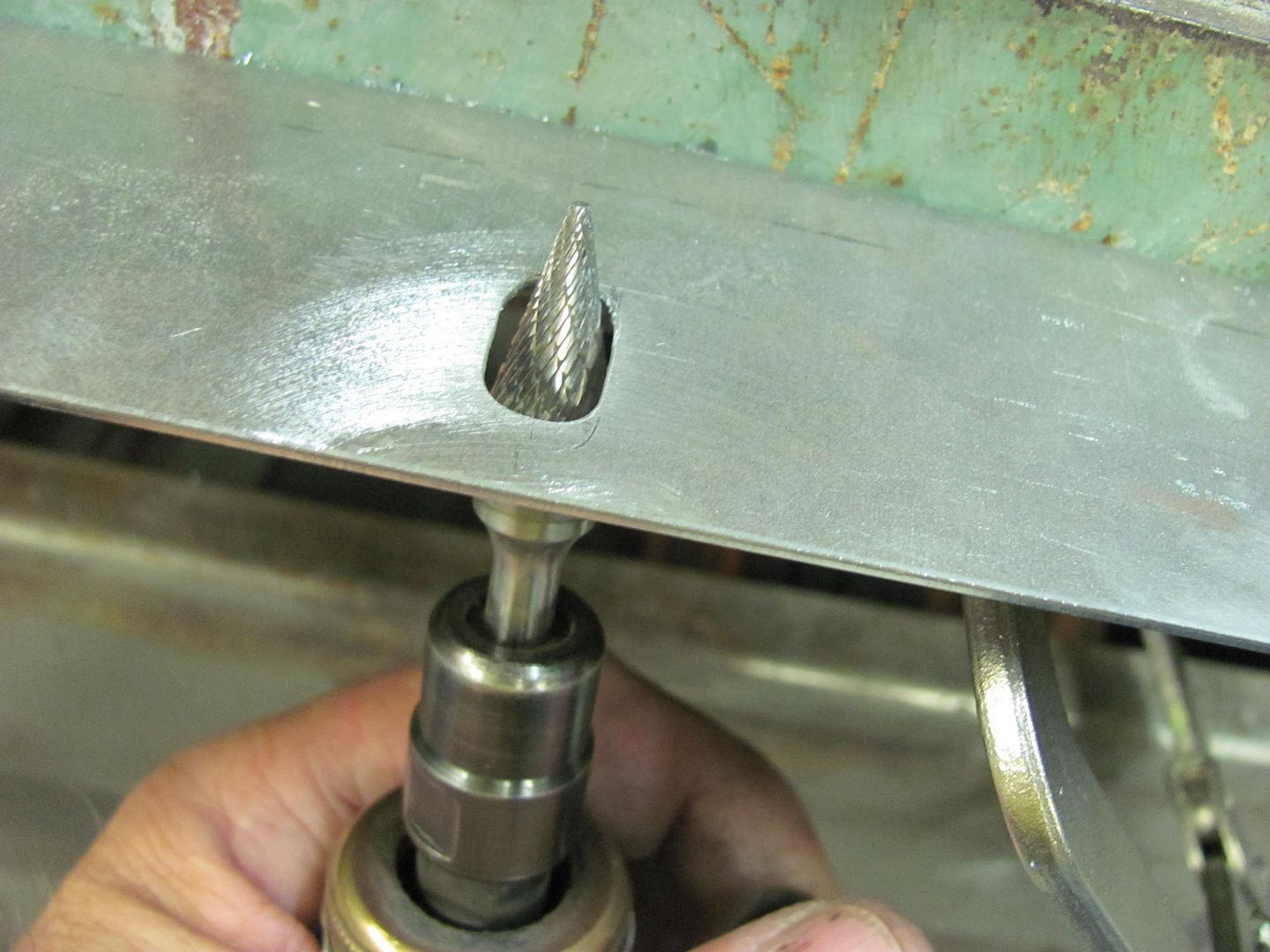
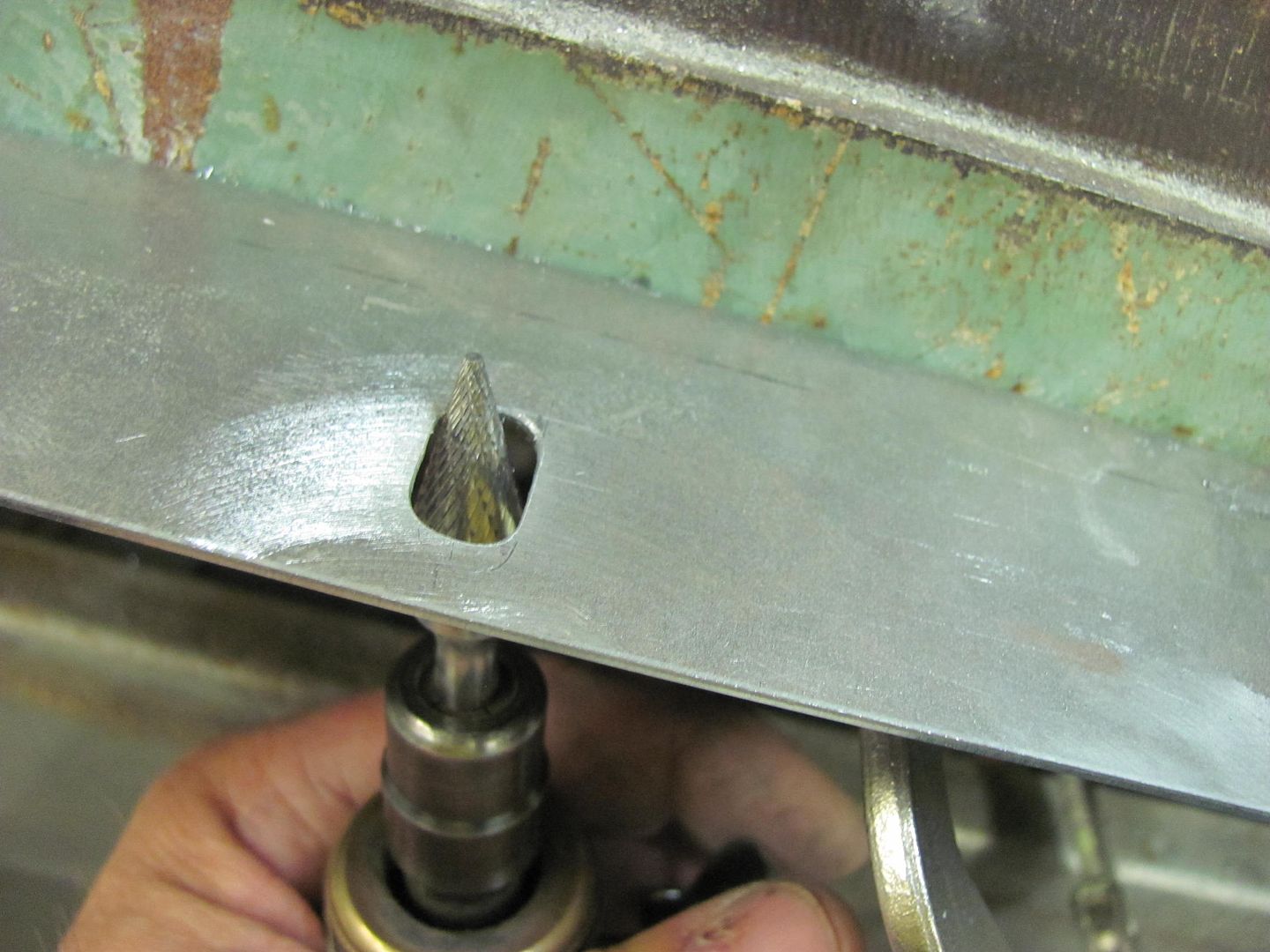
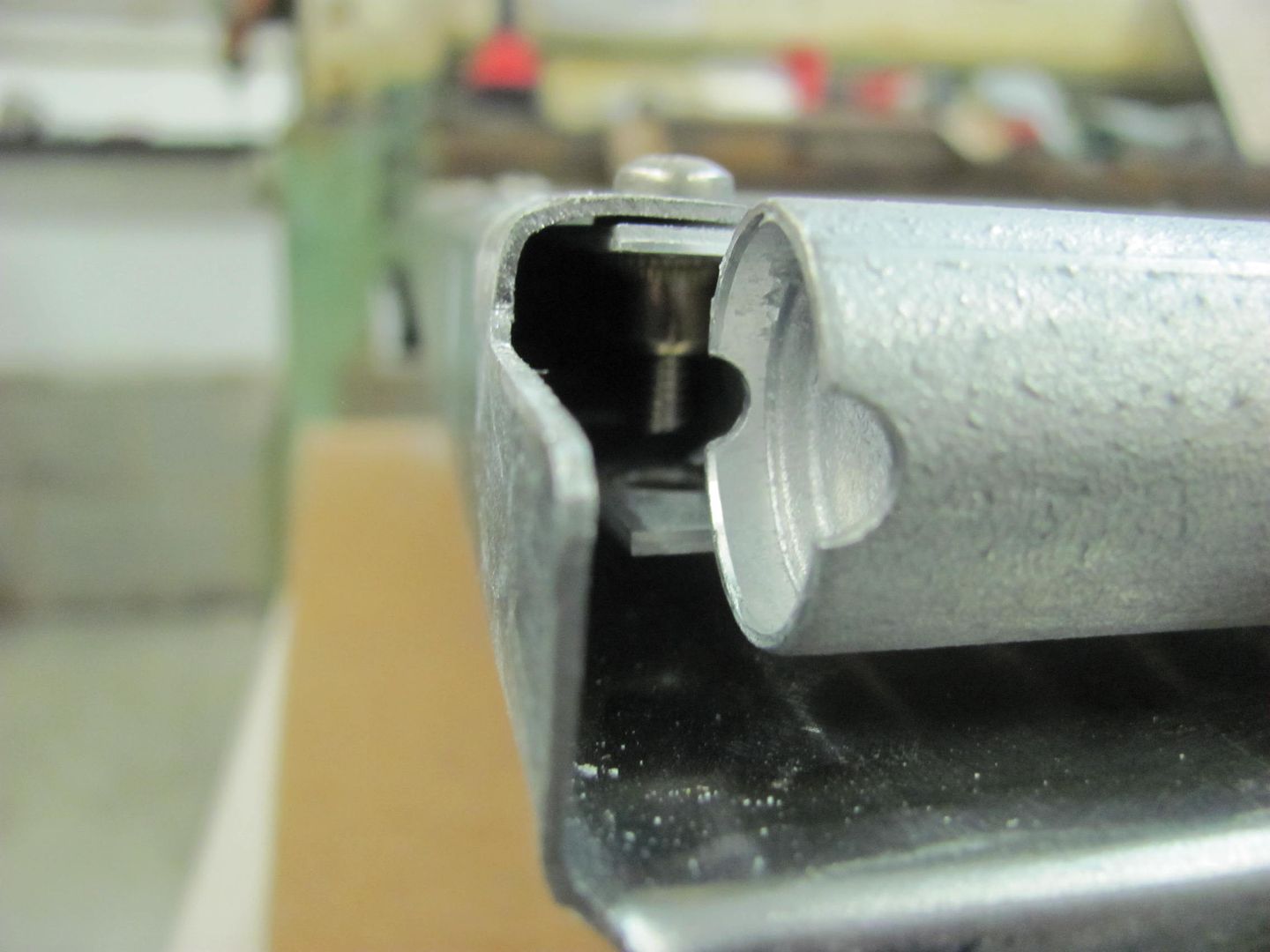
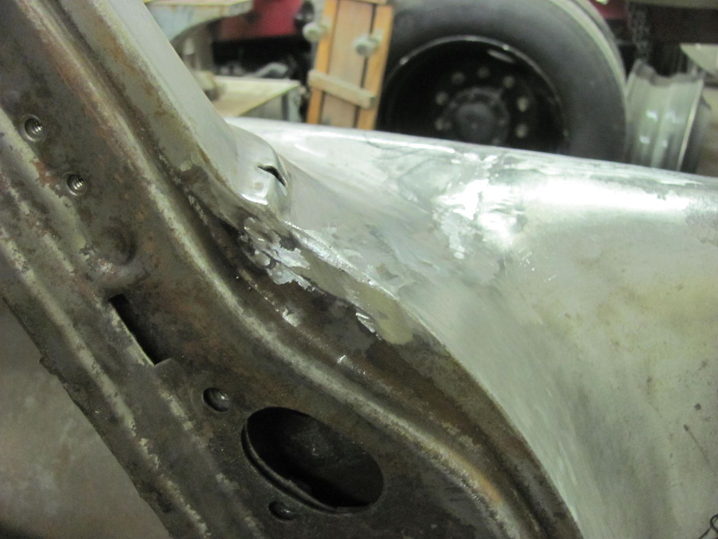
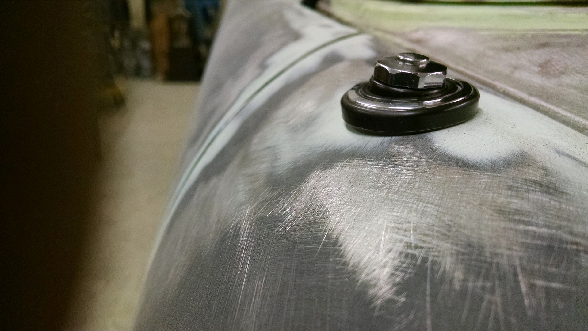
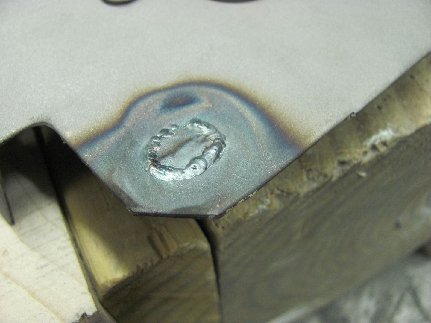
Yes, that there little X was a Phillips bit.....
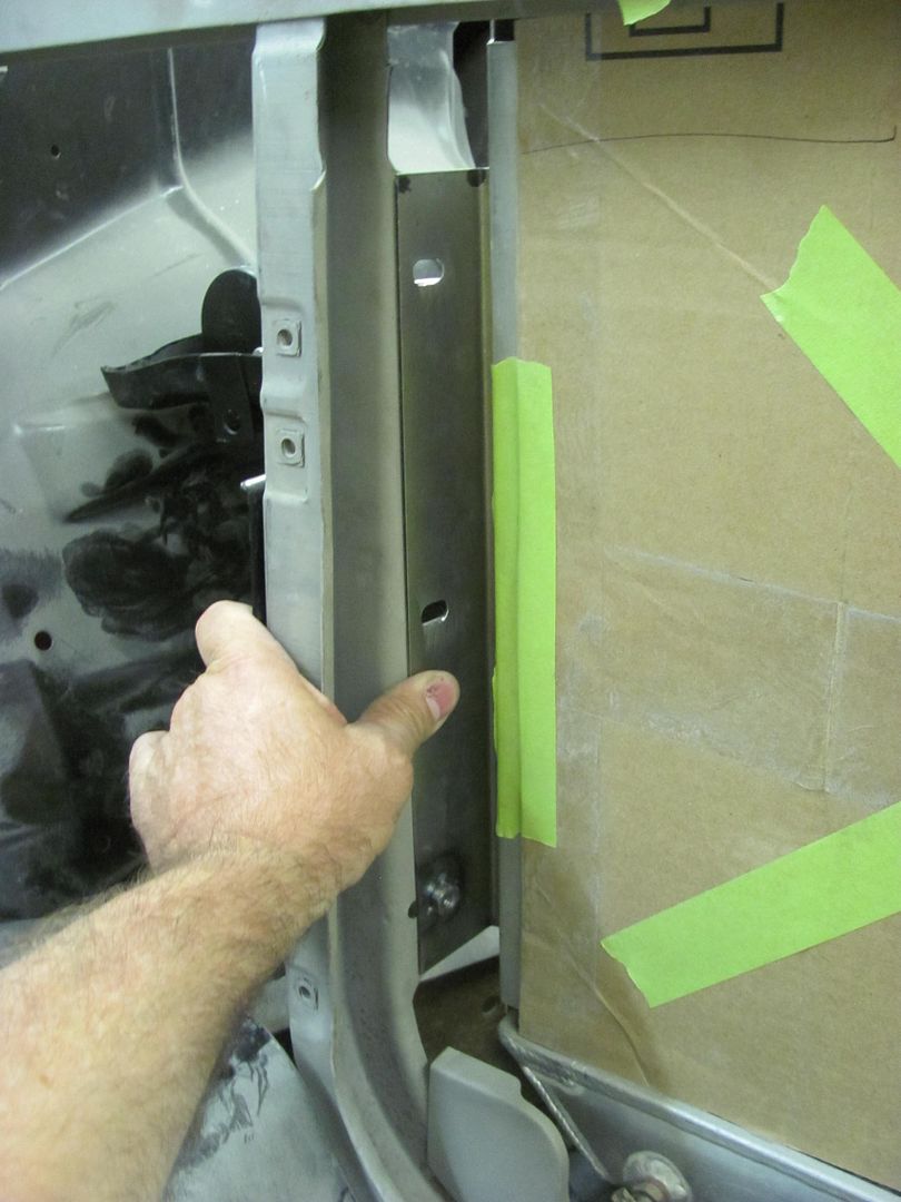
 BTW.......OUCH!!!!!!!
18v milwaukee drill, oak pallet, screw jumped sideways quicker than the thumb. Definite ouch.
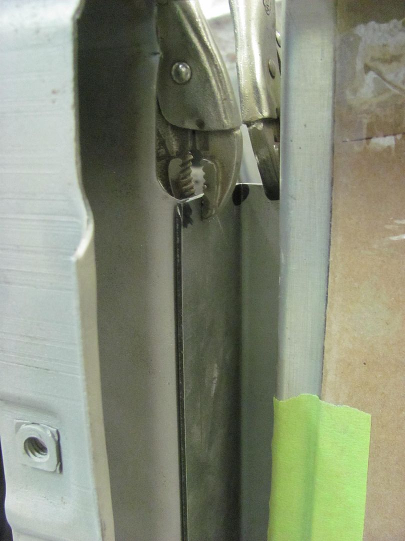
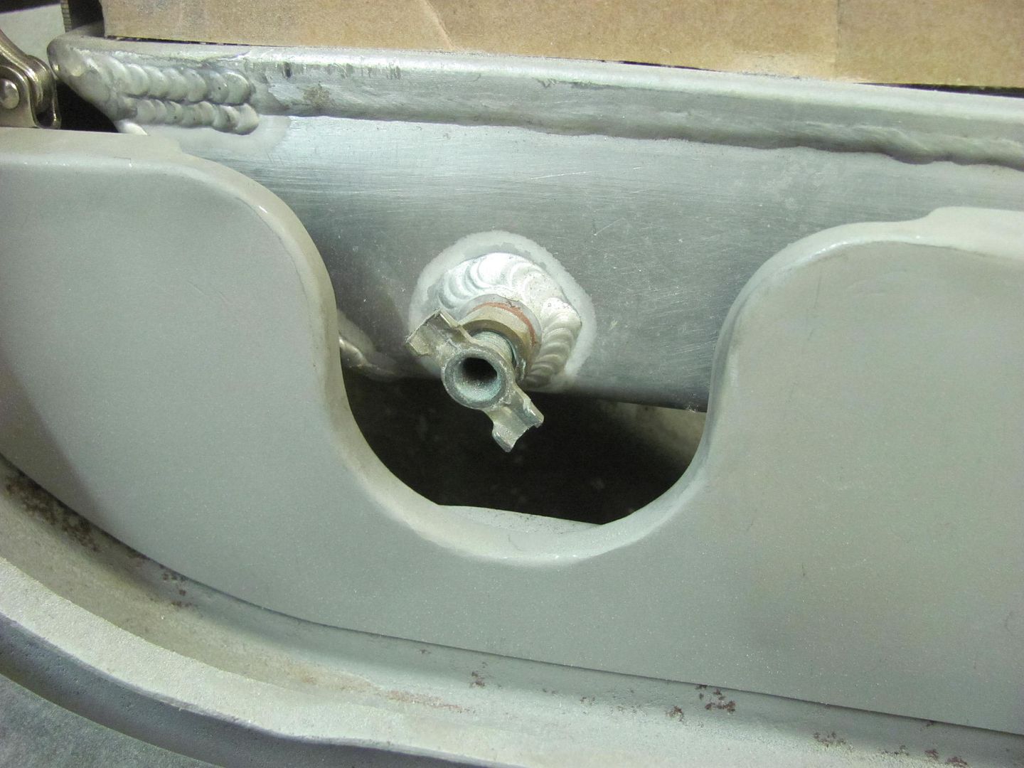
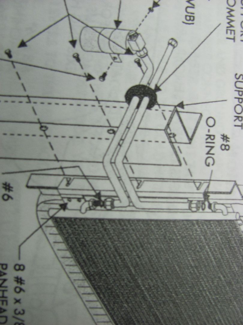
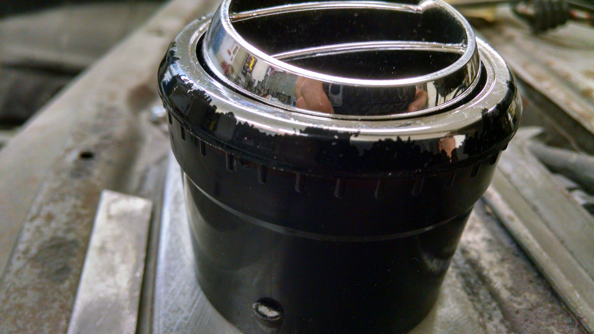
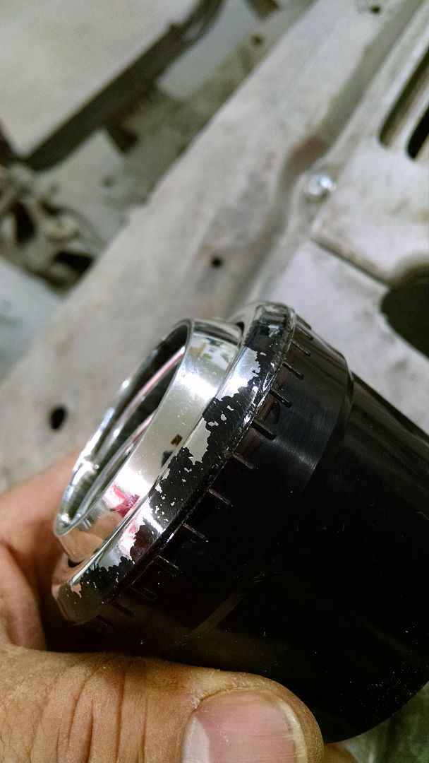
Started with a test fit of the power antenna the owner had bought, installed somewhat easily and even clears the door hinge when closed by 1/4". But this trim ring on top is just......obnoxious. Anyone use a power antenna that is a bit easier to hide?


 ).
).


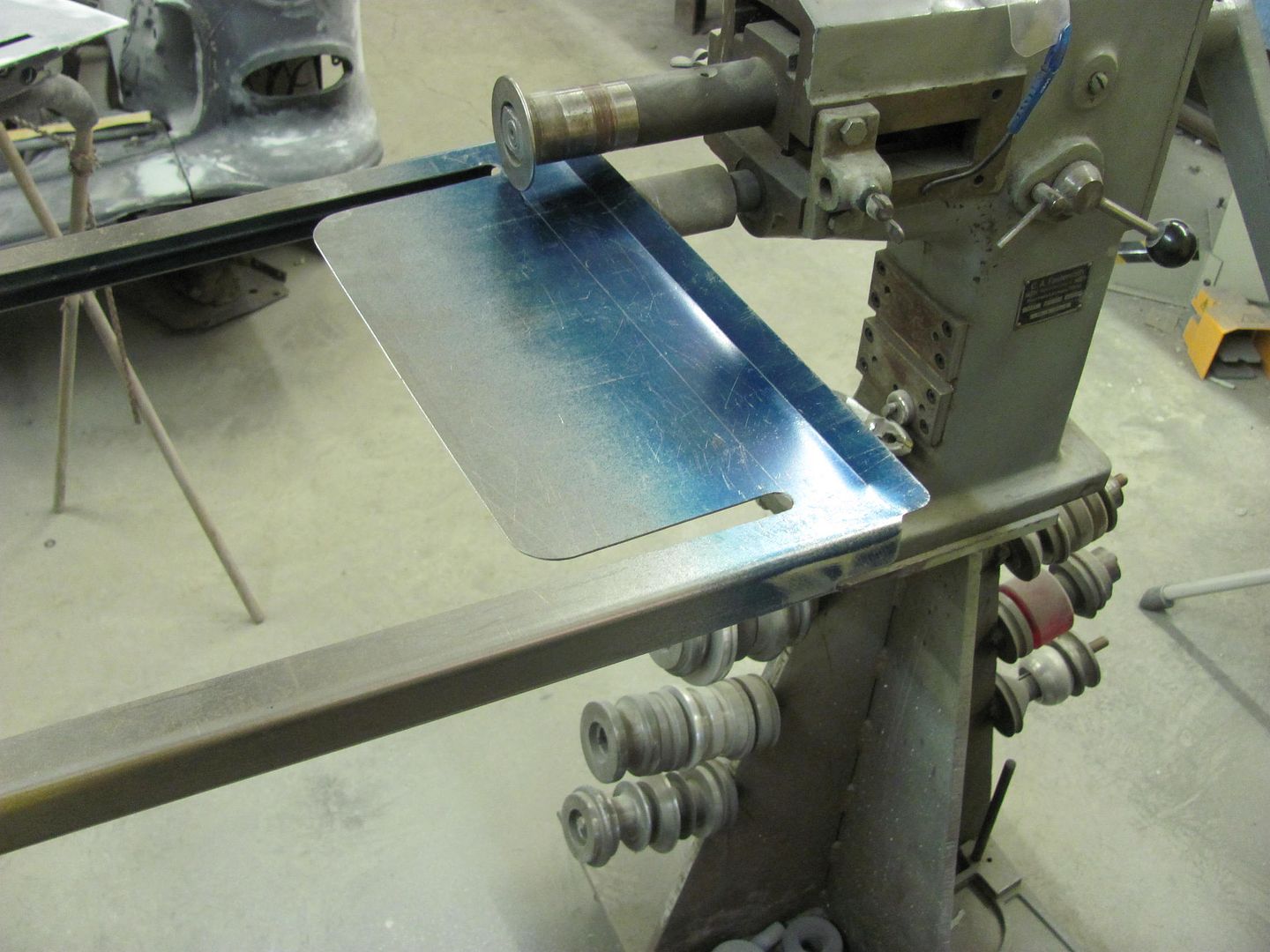
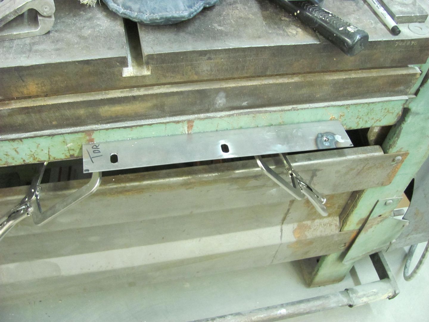
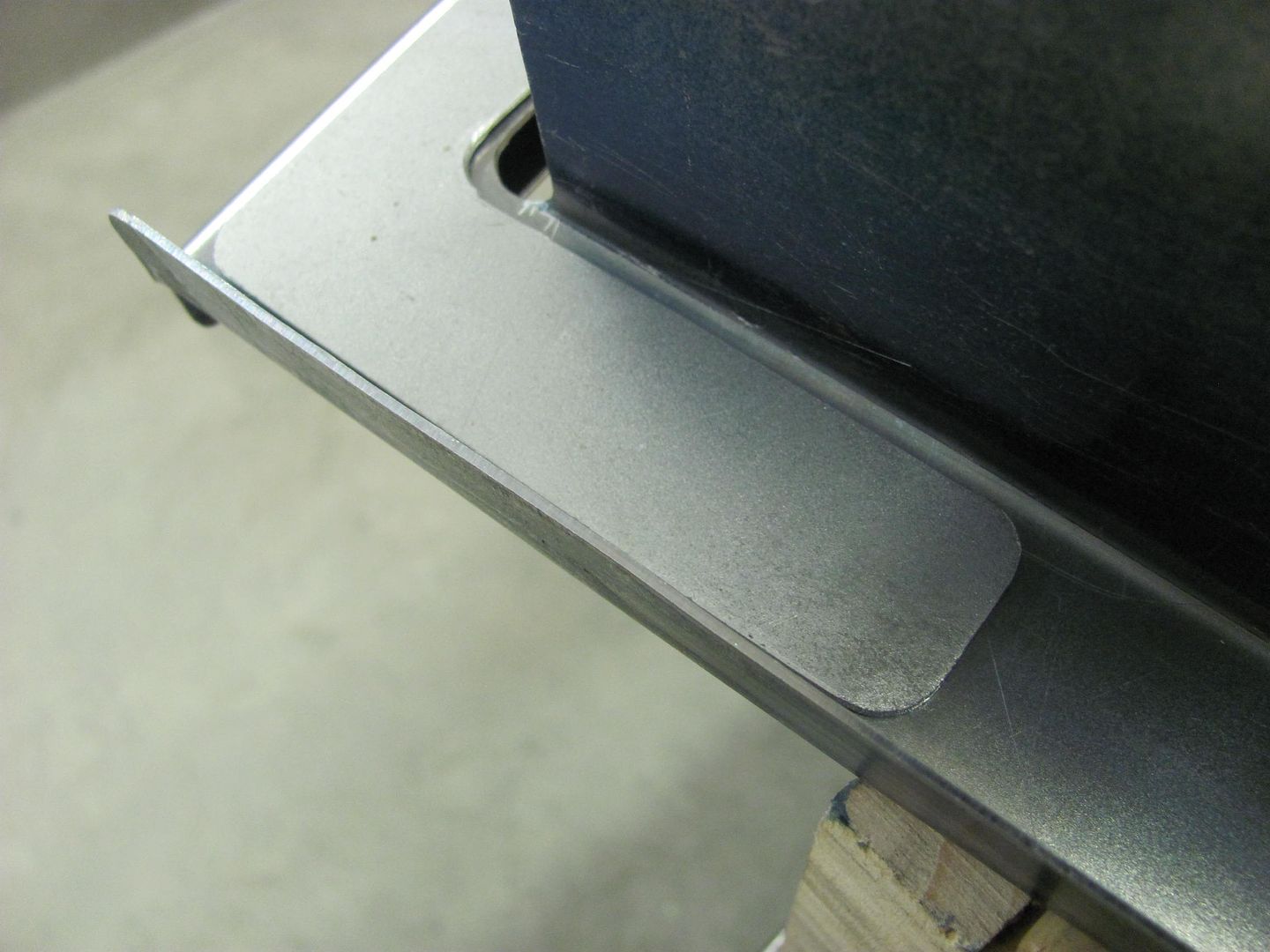
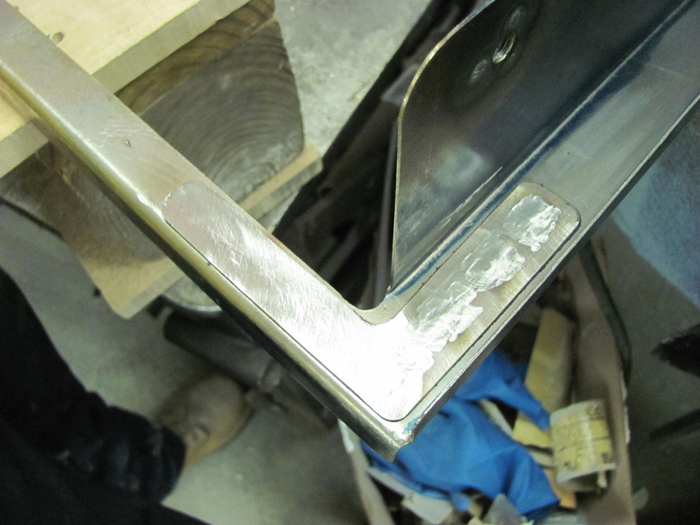
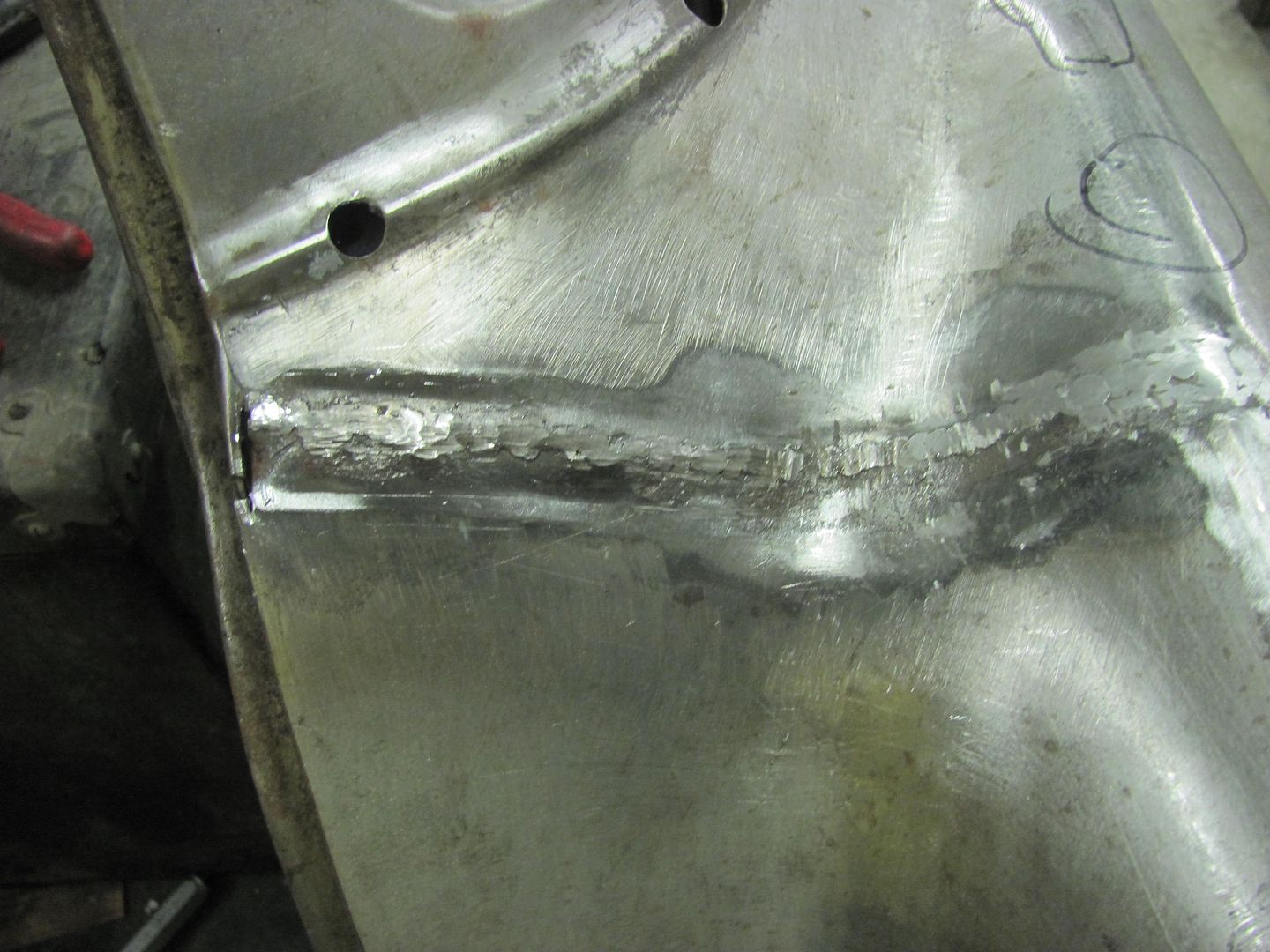
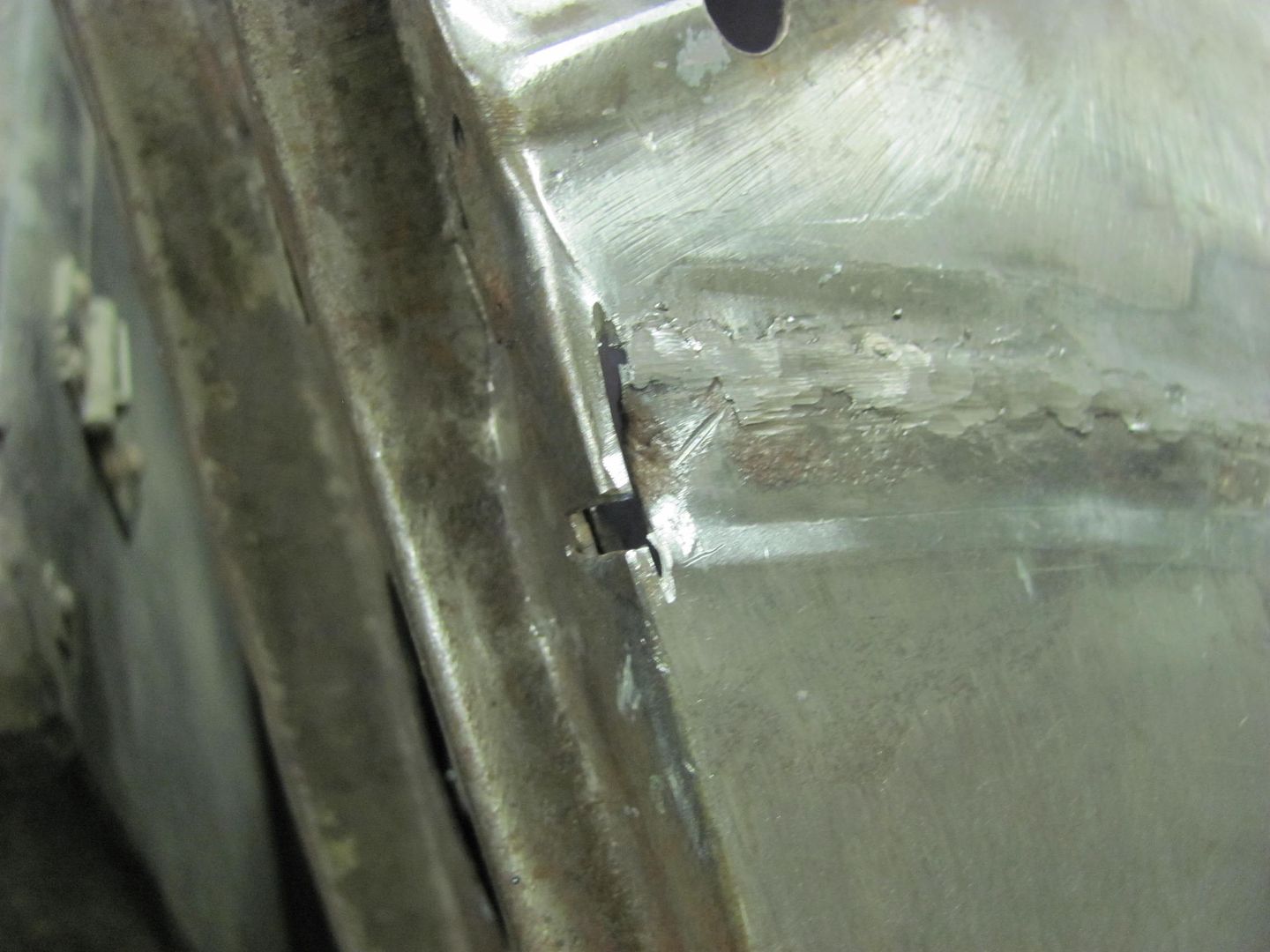
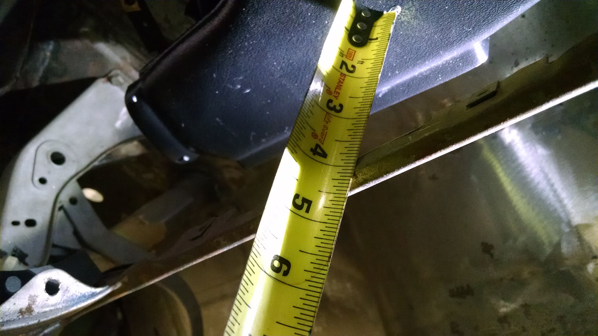
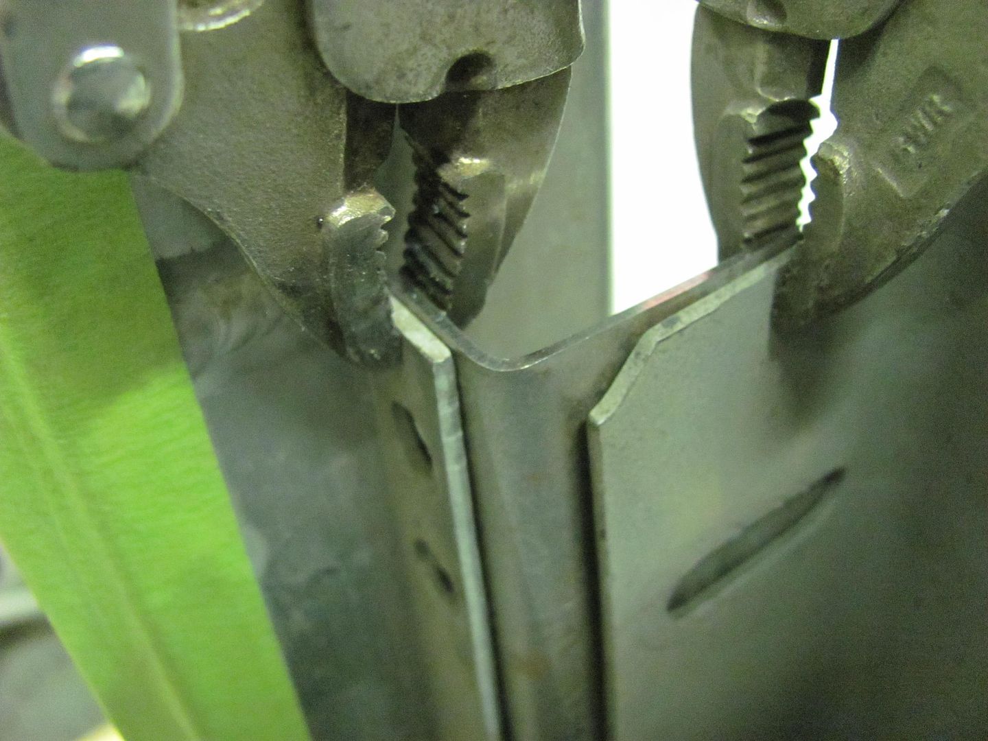
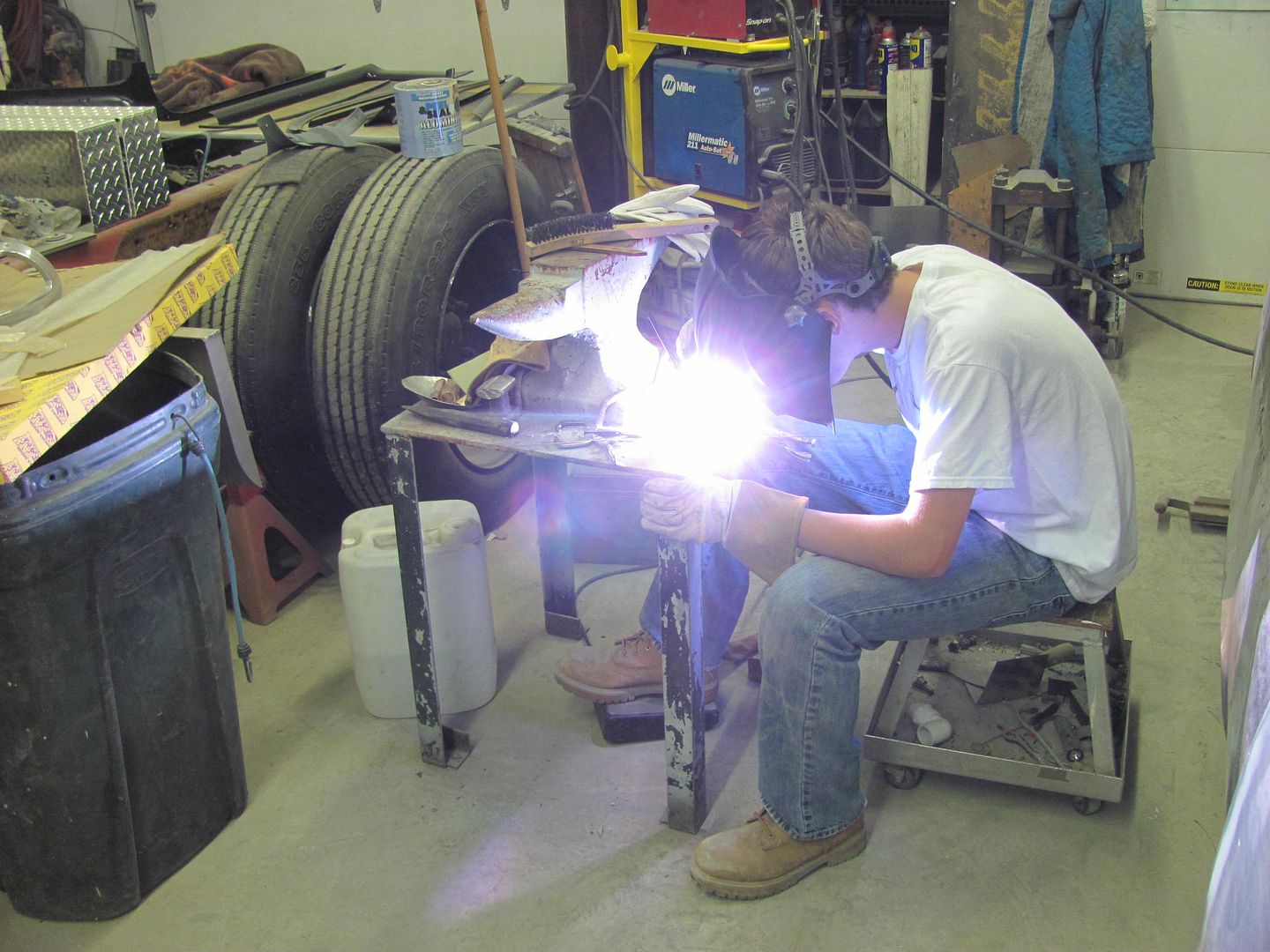
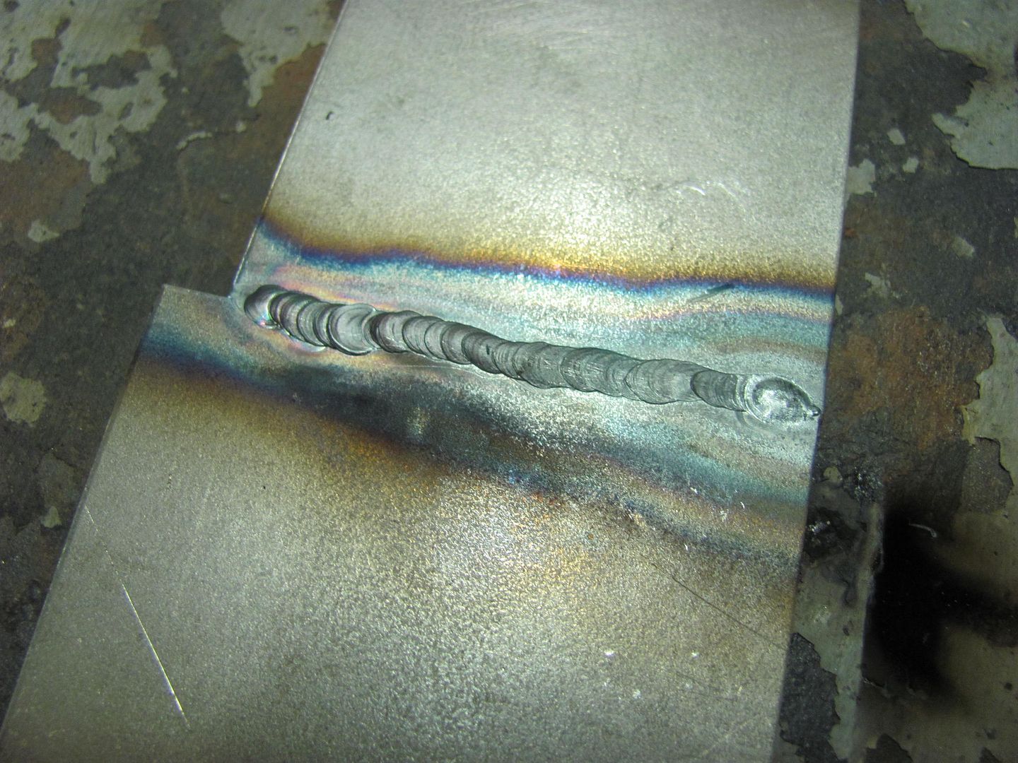
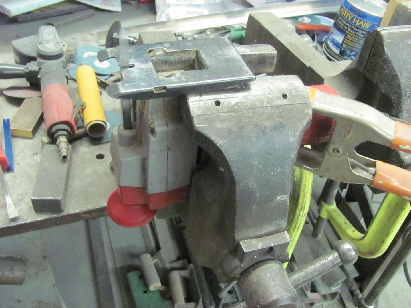
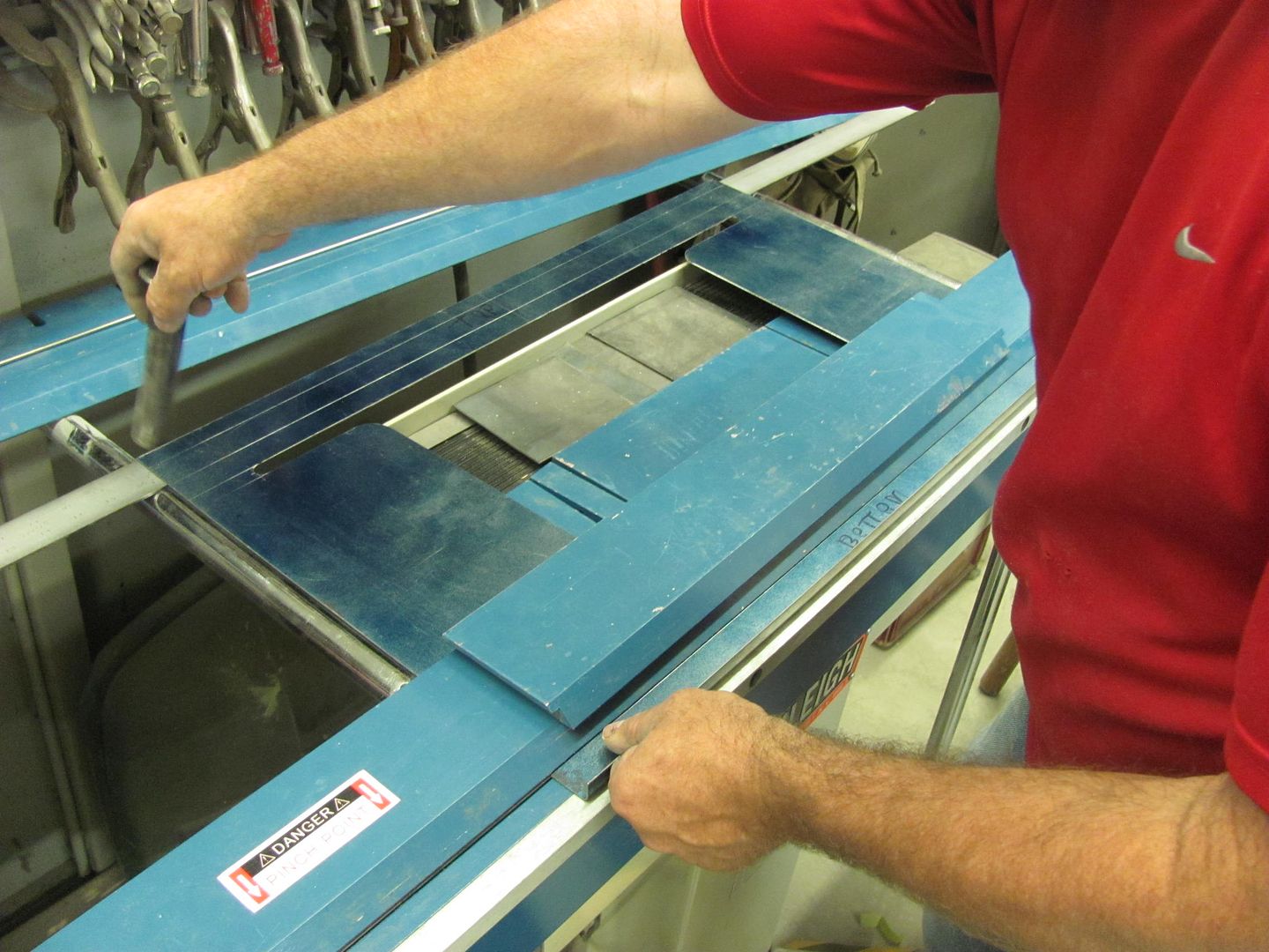
Well tonight I had an emergency repair to perform.. One of my Brother-in-law's is a career finish carpenter and today, after 34 years of using it without incident, cut a slice into his carpenter's square. He had ground it down some in preparation for loading it up with JB weld, and then thought better of it and called me to check on the possibility of welding. It was aluminum, and although it's been a good while since I've used the Tig on aluminum, let's give it a go...
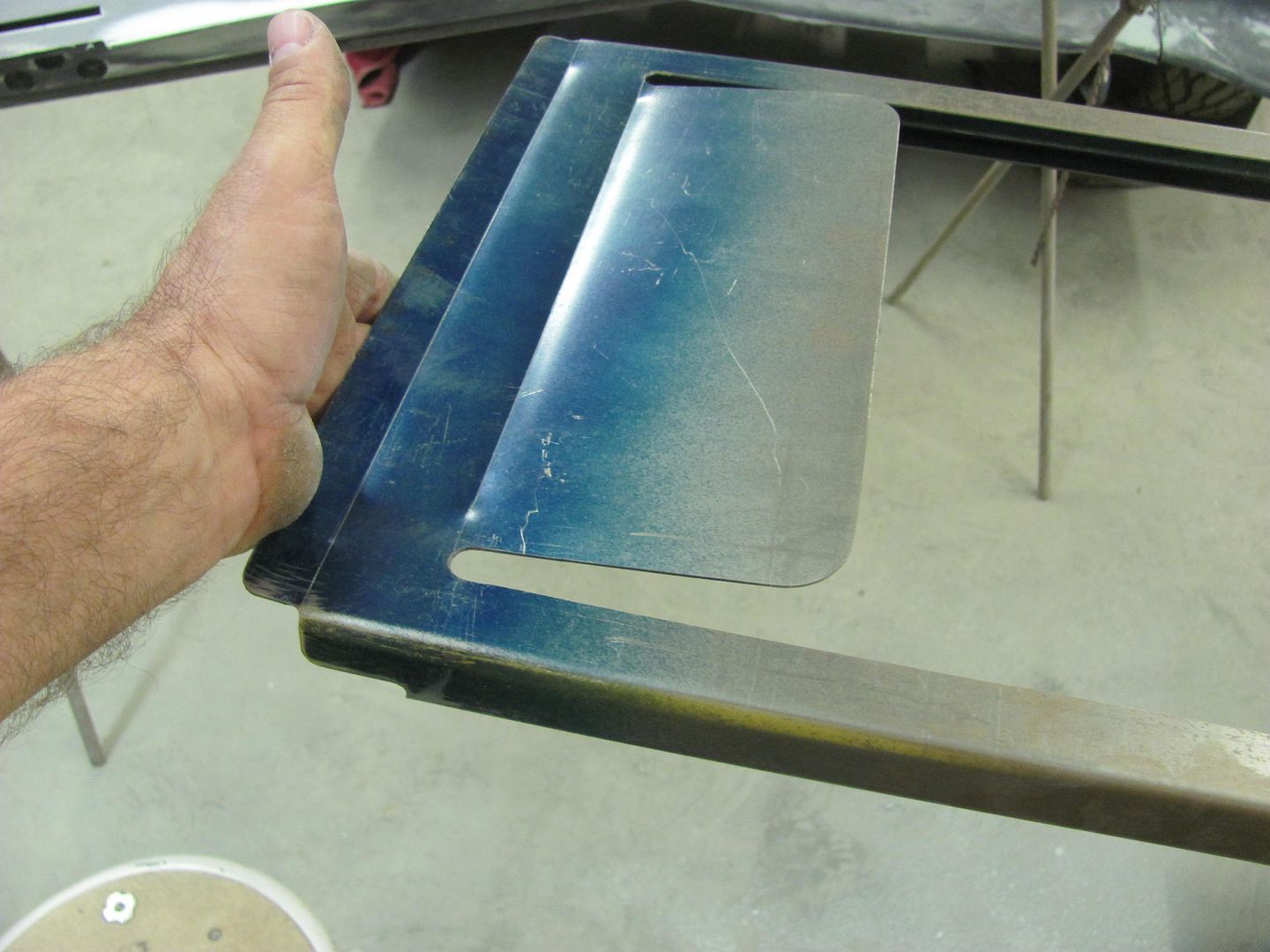
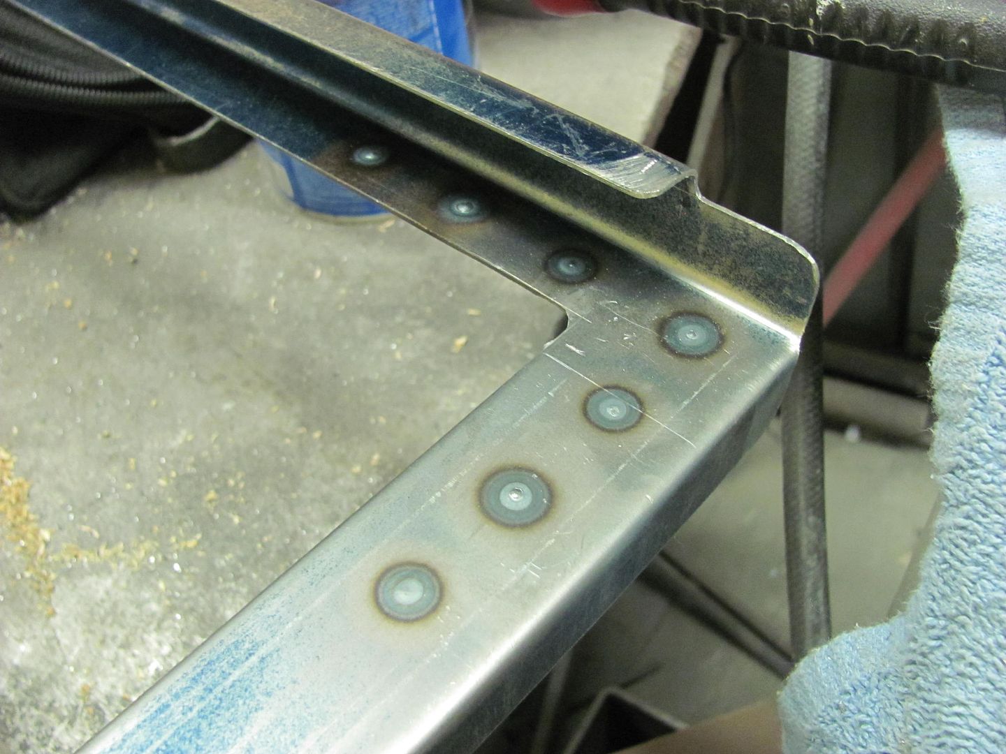
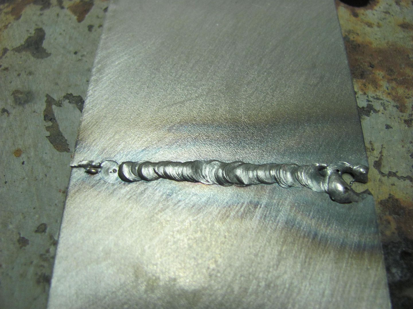
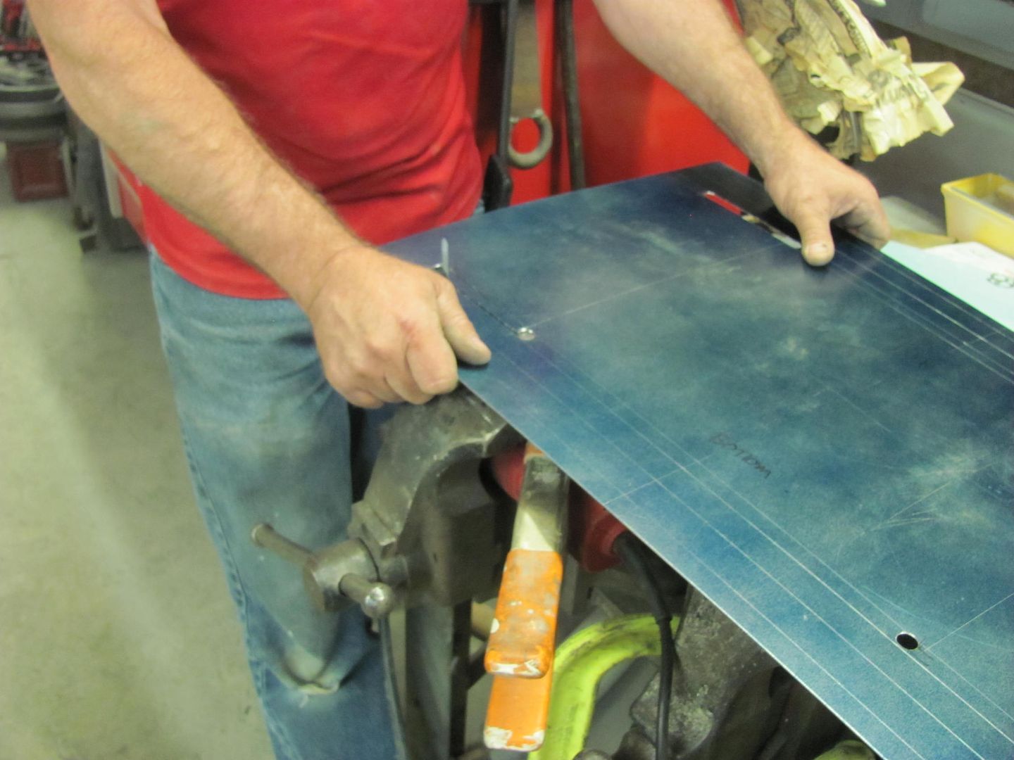
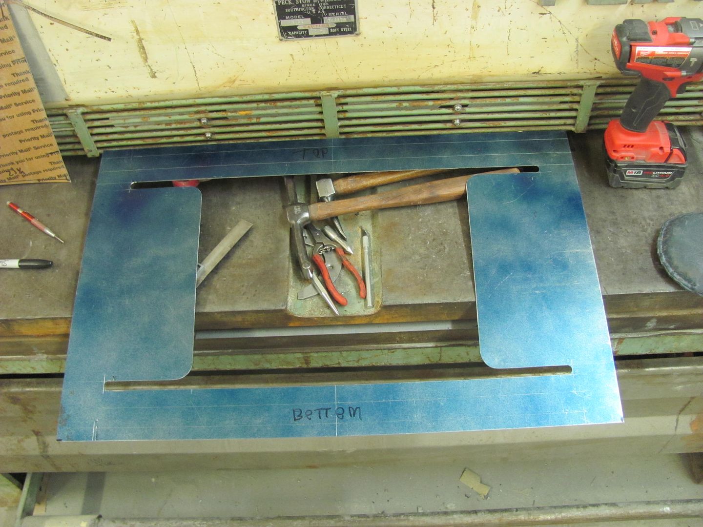
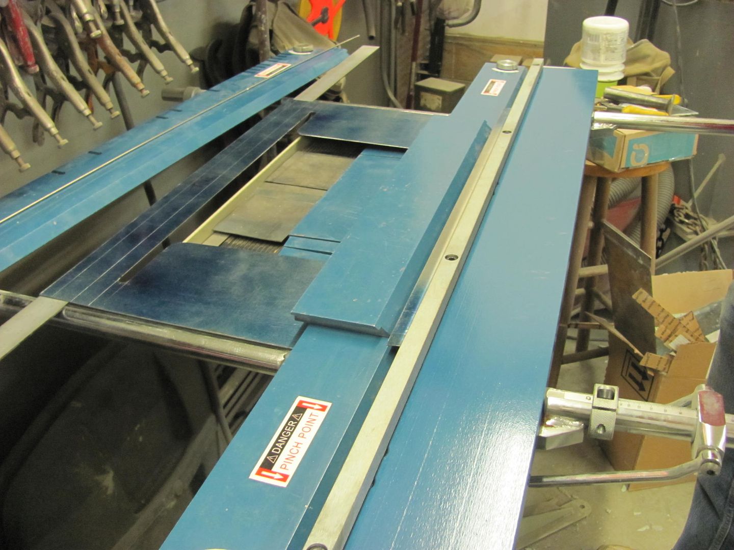
Nice and straight still....
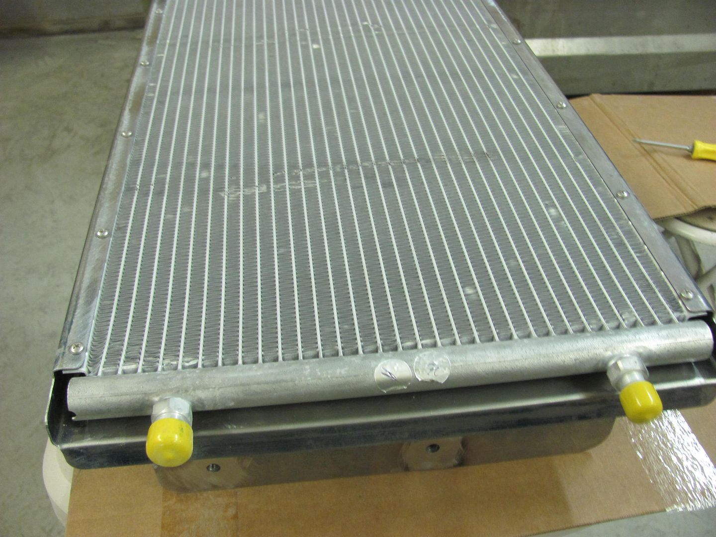
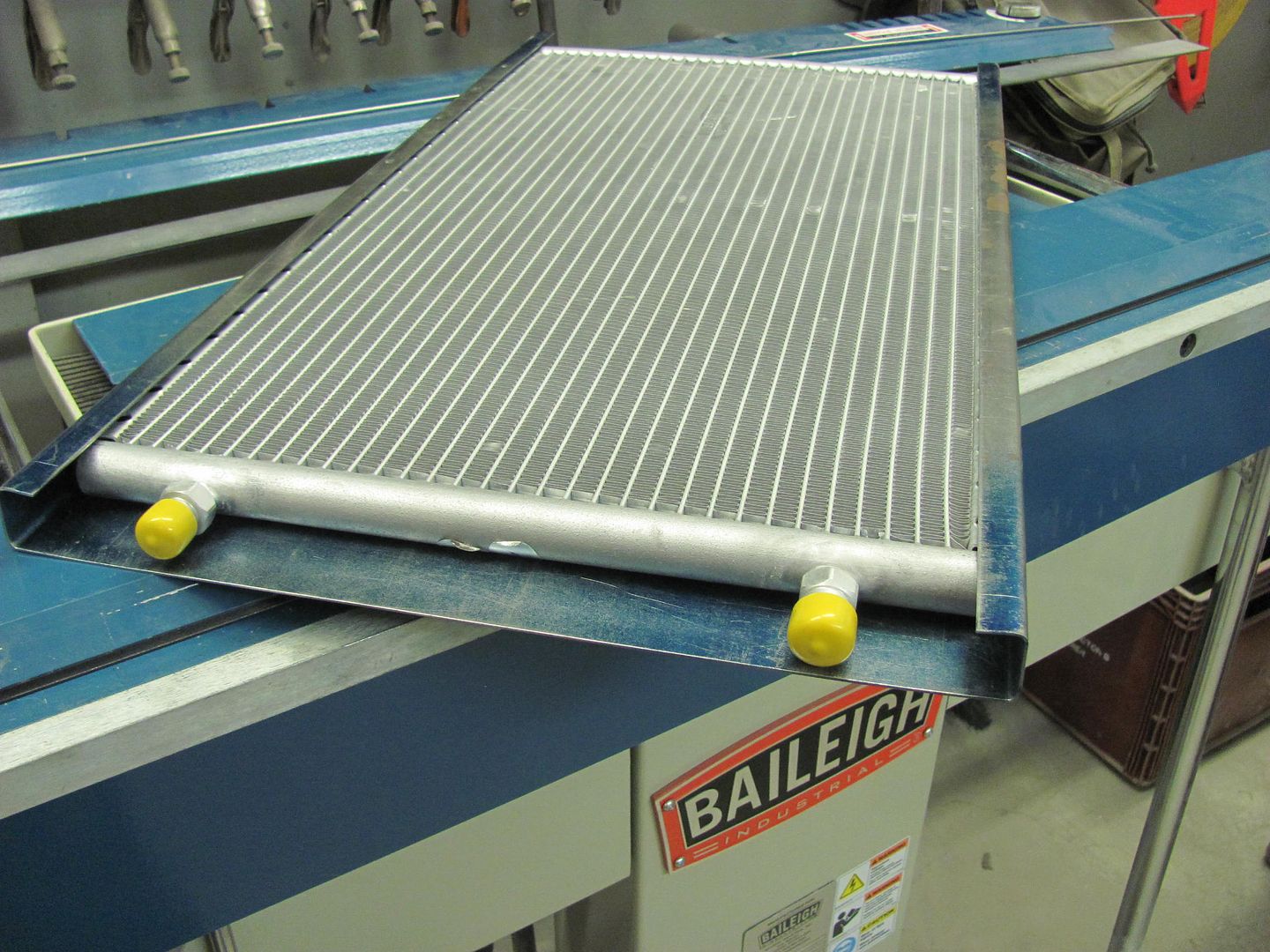
All ready for him to use again tomorrow..
Actually I'm happy to hear that. I've tried flux core wire, MIG and even DC TIG and I just can't get a tack to stick -- really hard to see through all the smoke. Even with a copper backer I blow holes every time. Planishing also just seems to make it worse. I'm thinking a bigger hammer -- just need to find my BFH....Plus, I have never had good luck welding the Vette body panels.