
You are using an out of date browser. It may not display this or other websites correctly.
You should upgrade or use an alternative browser.
You should upgrade or use an alternative browser.
MP&C Shop Projects
- Thread starter MP&C
- Start date
gelierb
Well-known member
Personally I prefer the old style gauges. Can't remember if you got David Gardiner's restoration DVD or not, but it has a good tutorial on it for OA welding. IIRC, he uses about 2-3 lbs on both O & A.
Thanks Robert - bought the DVD - lots of good stuff on there. Funny, I had just bought a piece of RR rail/anvil at the local steel plant for $15 and he seems to use one a lot
") .
. Picked up a Victor set (Journeyman 450) mostly to get the big old style gauges and will try to use the big torch for heating and maybe some cutting. Ordered a Victor J-28 handle with a #1 welding tip so now I'm working out what kind of hose/leader/flashback arrestor to put together for the small torch. All in good time

Last edited:
don long
Well-known member
Robert
I haven't posted very often but follow along very intently
You have given me a ton of tips in metal bending Thank you
It is becoming quite apparent to me that after I get away from the fiberglass work I am going to need a good bead roller
Your thread is very informative and interesting even to an old bodyman like me
Thanks again
Don
Don, thanks for taking time to post, glad to hear some of the info is helpful.. I'd say the bead roller is one of the most used pieces of machinery in my shop, second only to the welder..
Sorry for the slight hiatus, been in UK and just got back this past weekend. Time to catch up on what we had done before I left and what Kyle did while I was gone to take up my slack..
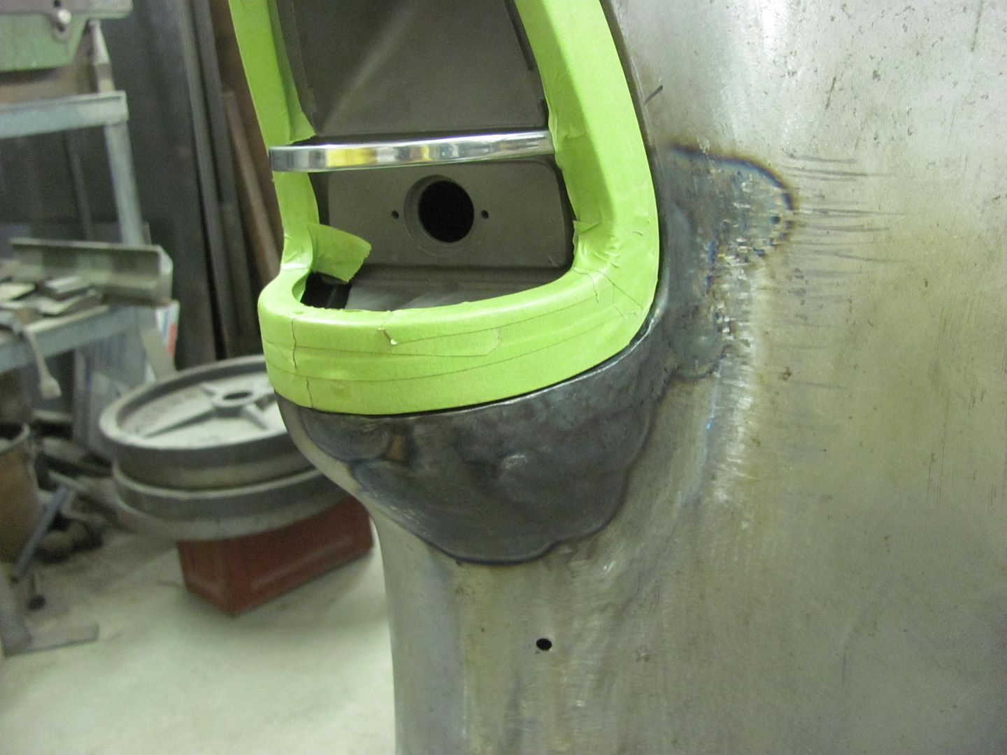
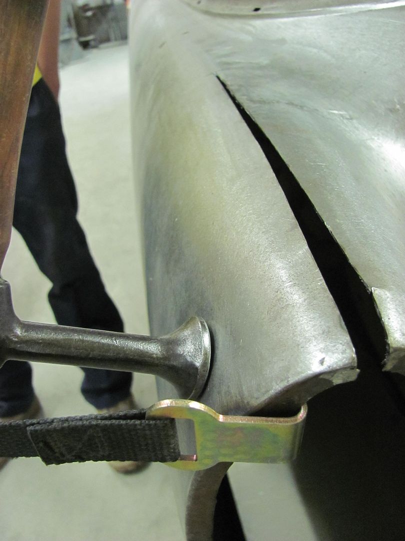
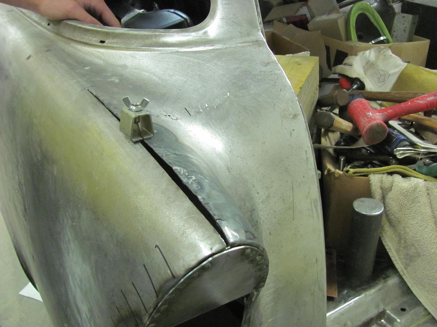
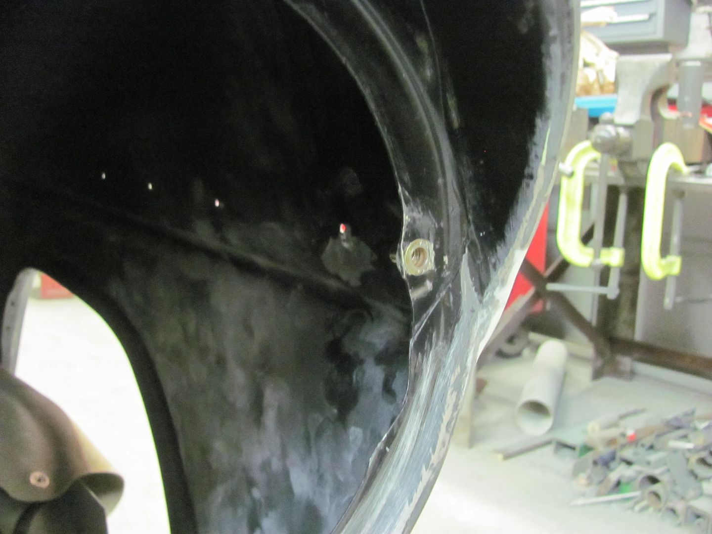
Part of our fitment issue with the passenger tail light was that we are installing the "hidden fuel fill" which required the removal of the brace welded in the opening. Next, when the old quarter was cut off and the new one installed, without the brace in place both pieces tended to wrap to the right, which can sort of be seen in the following picture, where its flush above the inside corner and rotates to the right upwards of that. The outer quarter was rotated in a similar fashion. We weren't having much luck in resolving the issue with the top weld seam remaining, so a relief cut was added, a restraint device employed to make use of some off dolly bumping to eliminate some of the right rotation. I didn't get a good picture of it, but you can see where the inner quarter comes in considerably upwards of the tail light right corner..
Anchor
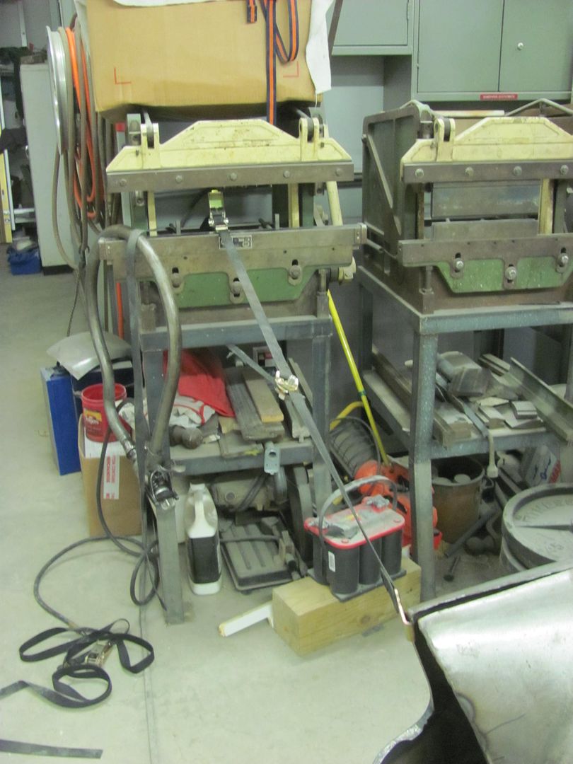
Off-dolly bumping...
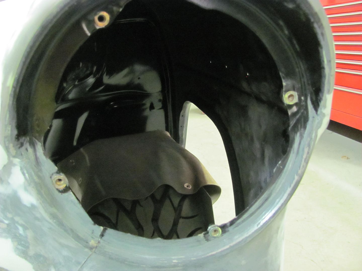
Then some shrinking was used to pull in the inner quarter, and a 16 ga plate used to hold things in place while the top seam was re-welded.
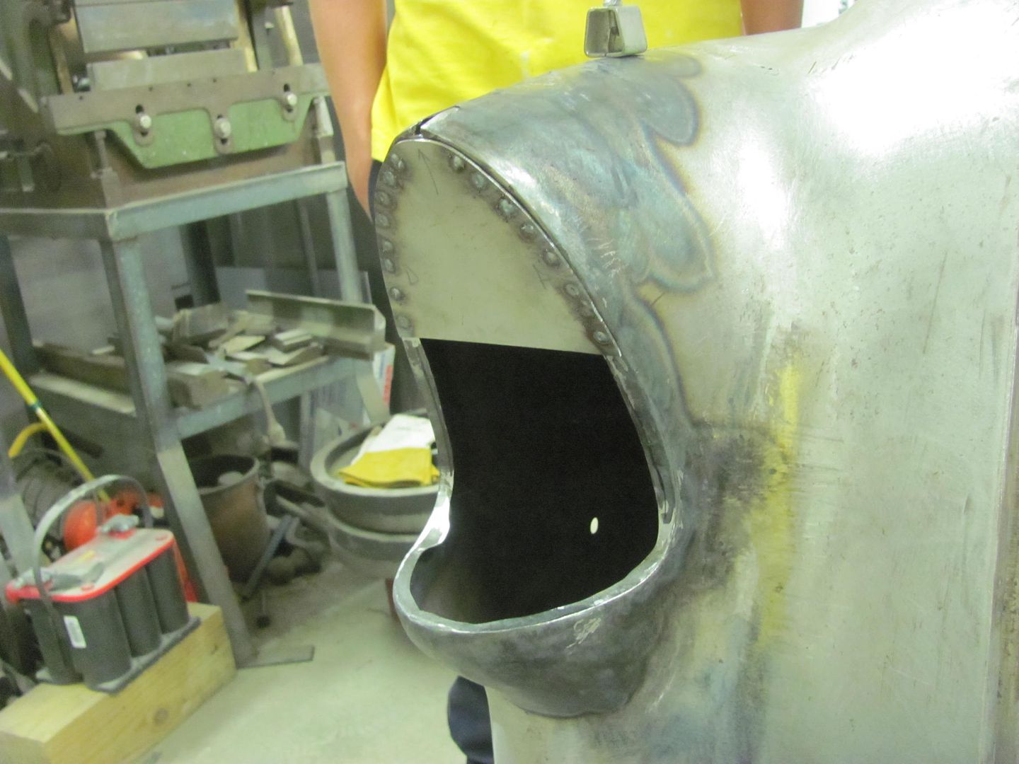
Kyle got the seam welded closed...
And temporary brace removed...
Much better, almost ready to tackle the "fuel door" pivot...
Sorry for the slight hiatus, been in UK and just got back this past weekend. Time to catch up on what we had done before I left and what Kyle did while I was gone to take up my slack..
Part of our fitment issue with the passenger tail light was that we are installing the "hidden fuel fill" which required the removal of the brace welded in the opening. Next, when the old quarter was cut off and the new one installed, without the brace in place both pieces tended to wrap to the right, which can sort of be seen in the following picture, where its flush above the inside corner and rotates to the right upwards of that. The outer quarter was rotated in a similar fashion. We weren't having much luck in resolving the issue with the top weld seam remaining, so a relief cut was added, a restraint device employed to make use of some off dolly bumping to eliminate some of the right rotation. I didn't get a good picture of it, but you can see where the inner quarter comes in considerably upwards of the tail light right corner..
Anchor
Off-dolly bumping...
Then some shrinking was used to pull in the inner quarter, and a 16 ga plate used to hold things in place while the top seam was re-welded.
Kyle got the seam welded closed...
And temporary brace removed...
Much better, almost ready to tackle the "fuel door" pivot...
Divcod
Well-known member
I was in the UK the last few weeks and made a side trip to visit the Morgan Motorcar Co. Very interesting mix of traditional hand craftsmanship to high tec pressure forming of the wings and a bonded al frame. Welcome back like many others I enjoy your posts.
Last edited:
36racin
Active member
SIMPLY AMAZING!!!
^^^^What he said. The attention to detail is way beyond anything I have ever seen. I know your 15+ hours from my location but I'd still like you and your assistant to put your magic touch on my car body. I can't wait to see this car in color.
Todd
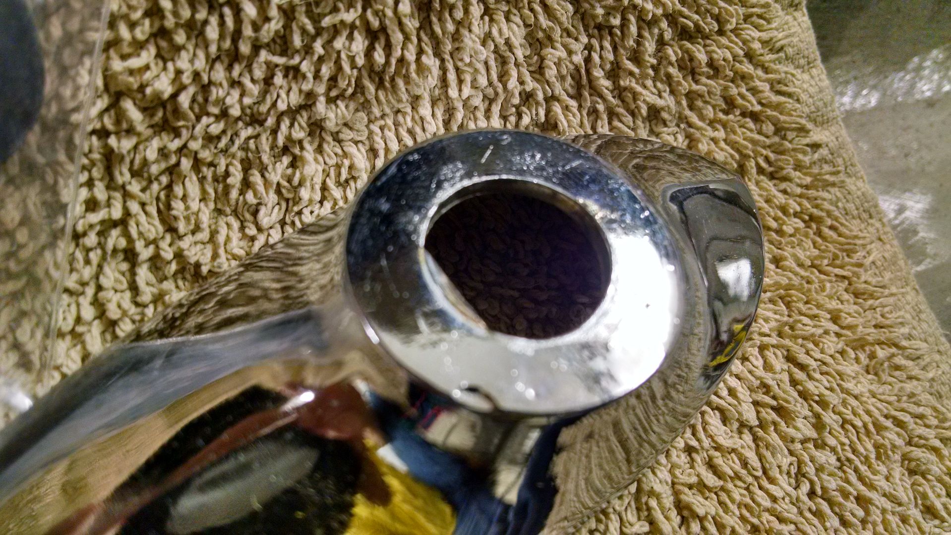
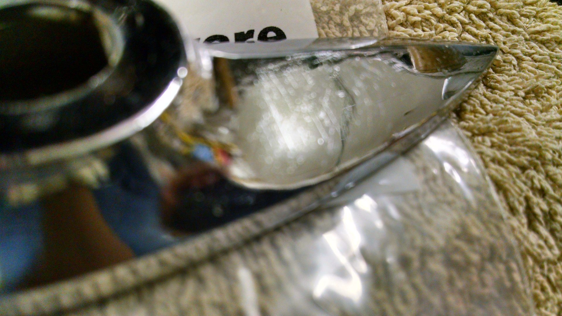
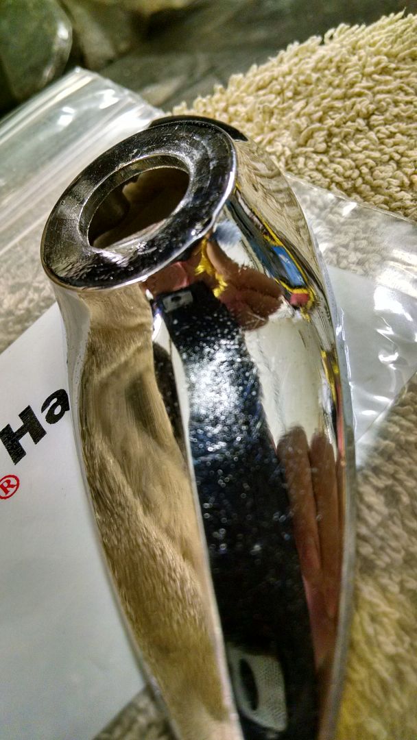
Got another care package in the mail... The new escutcheon for the antenna looks like it will work, the hole size matches the nut on the antenna and we'll just need to get rid of the flat spot/keyway in the hole. Only I don't think we'll be using this one. Between a recess under the chrome and visible scratches in it, this one's going back.
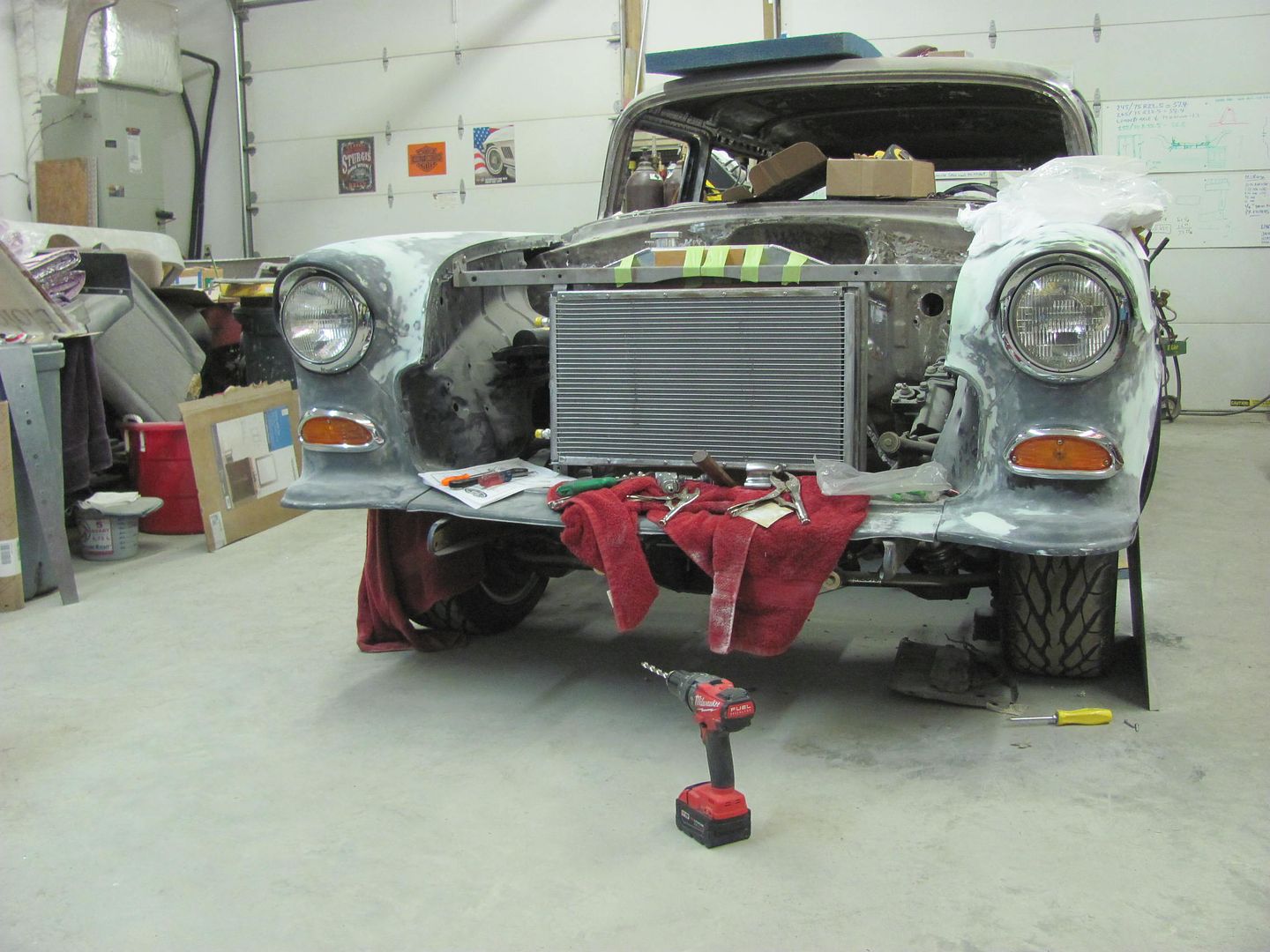
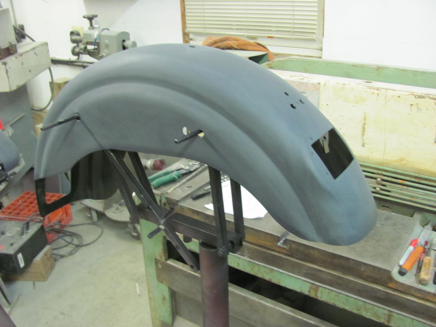
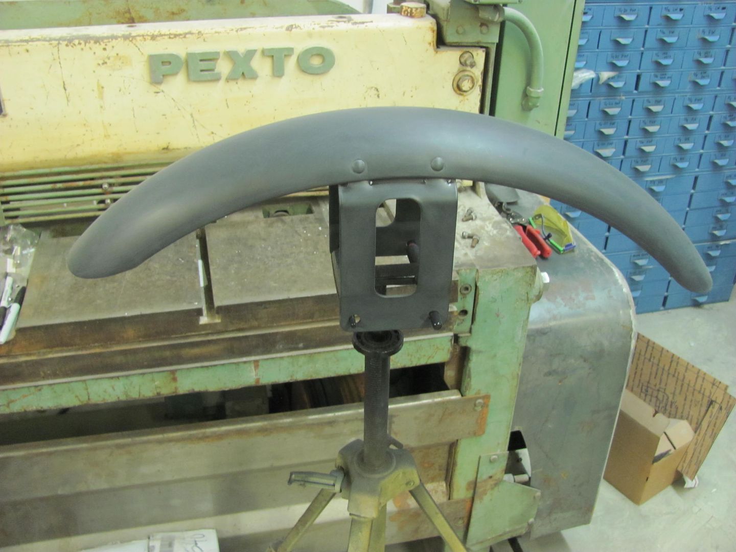
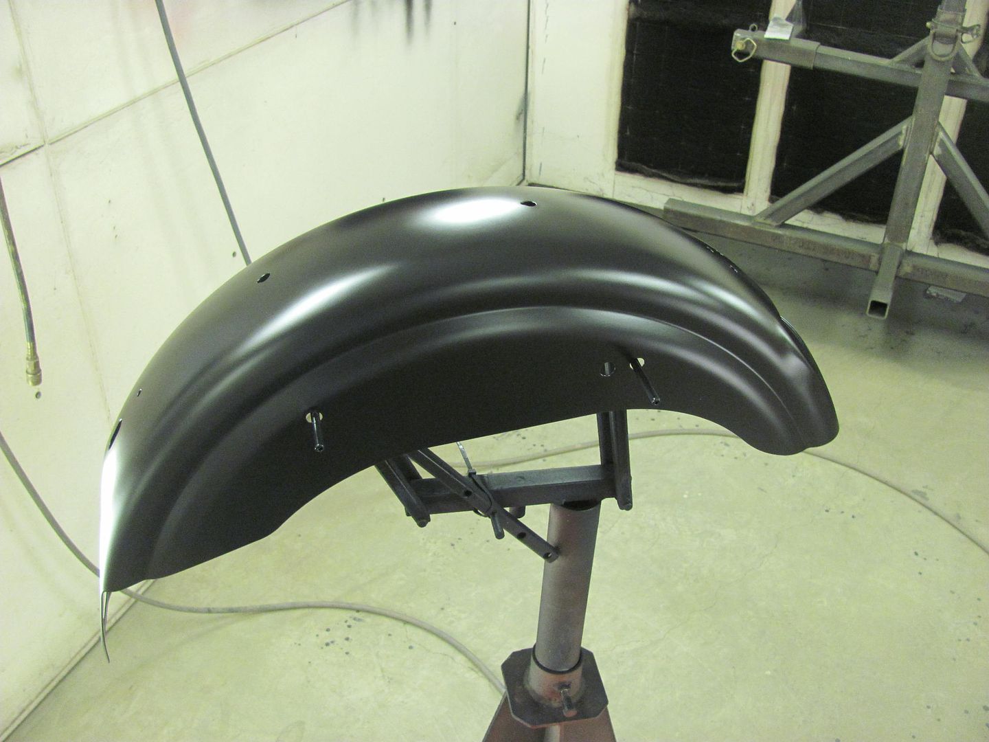
On to the next new pieces, hopefully these fit better, Reproduction headlight buckets..... wanted to test fit all the headlight and turn signal pieces before re-priming the fenders..
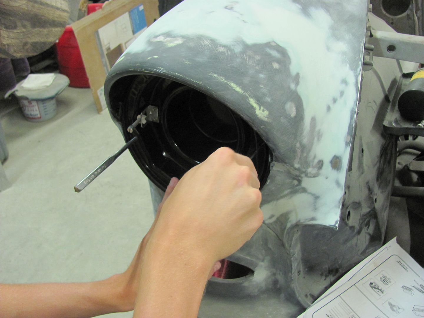
Decided to use some AVK rivet nuts over the u-clips..
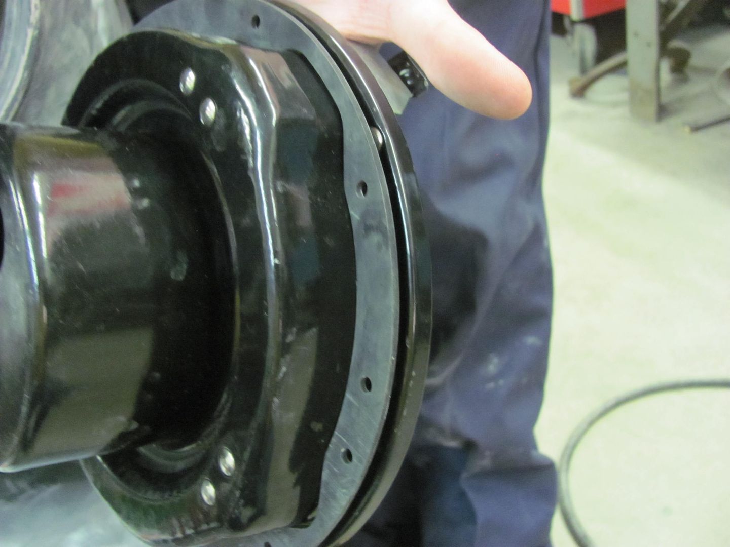
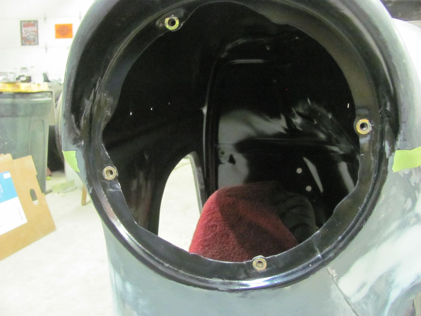
Parts fitted..
On to the next new pieces, hopefully these fit better, Reproduction headlight buckets..... wanted to test fit all the headlight and turn signal pieces before re-priming the fenders..
Decided to use some AVK rivet nuts over the u-clips..
Parts fitted..
shortykorte
Well-known member
Wow wow wow. I guess anything is possible with great skill and patience.
Mostly patience
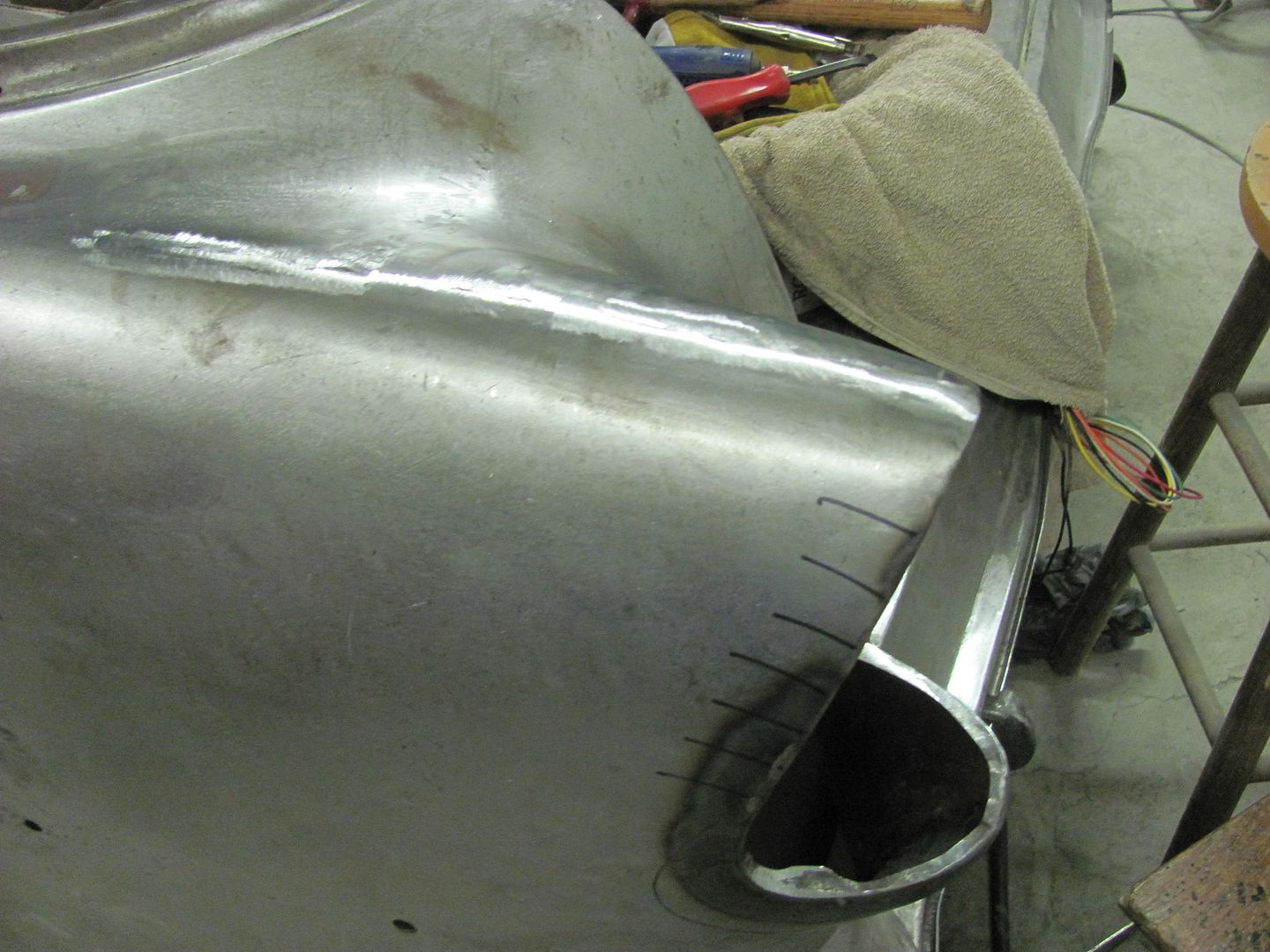
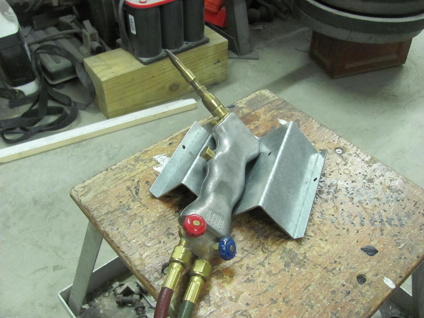
Well this isn't much of an update, but since Kyle was busy media blasting some parts I had torch and hammer duty.. So to have a place to drop the torch quickly, bent this up:
When the top seam was welded we had a slight bulge just in from the tail light. So some dime sized spots were heated and then hammered with glancing blows to bring things down a bit.. The fit of the tail light is much better now, and we've started the fitup of the motor assembly's mounting plate. Should get that welded in tomorrow..
gelierb
Well-known member
Mostly patience
Well this isn't much of an update, but since Kyle was busy media blasting some parts I had torch and hammer duty.. So to have a place to drop the torch quickly, bent ...
Nice torch holder! I just made this for my little J28 (custom rattle-can
) but I don't know if it's going to really work that well...
wasfast
Well-known member
Absolutely amazing attention to detail. I have wondered, casually, whether your Chevy or Don Long's Corvette gets color applied first. That's a close race!
My money's on Don..... 
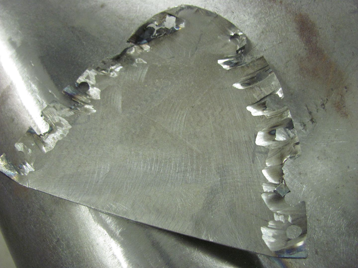
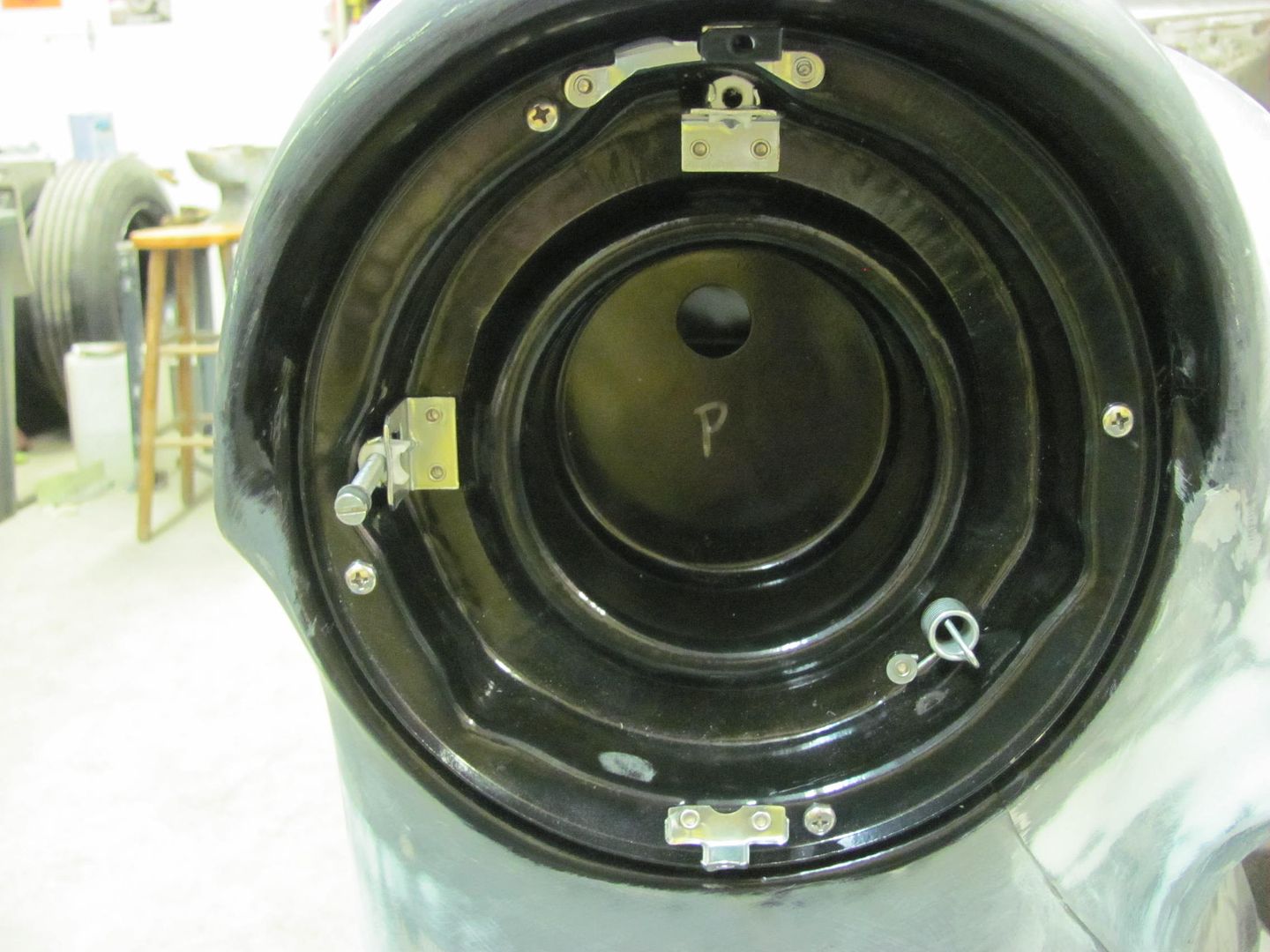
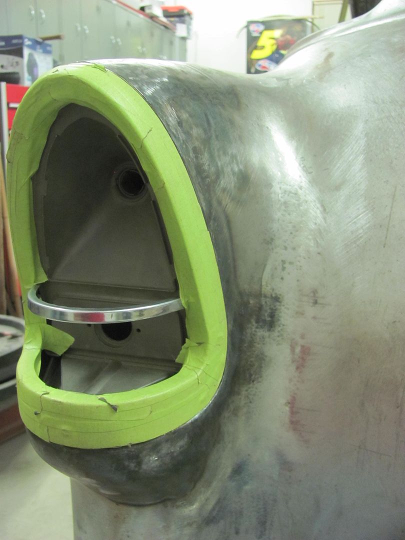
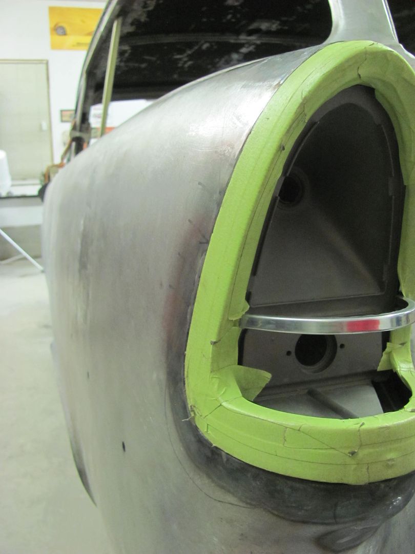
Worked on the Rocky Hinge hidden fuel door this evening. The mounting plate we made is plug welded to the tail light opening..
Slight trimming needed.....
Then some 3M body molding adhesive tape is added to the top of the pivot bracket and the lens pressed in place. Here's the initial test...
https://youtu.be/oZ6JYr988dc
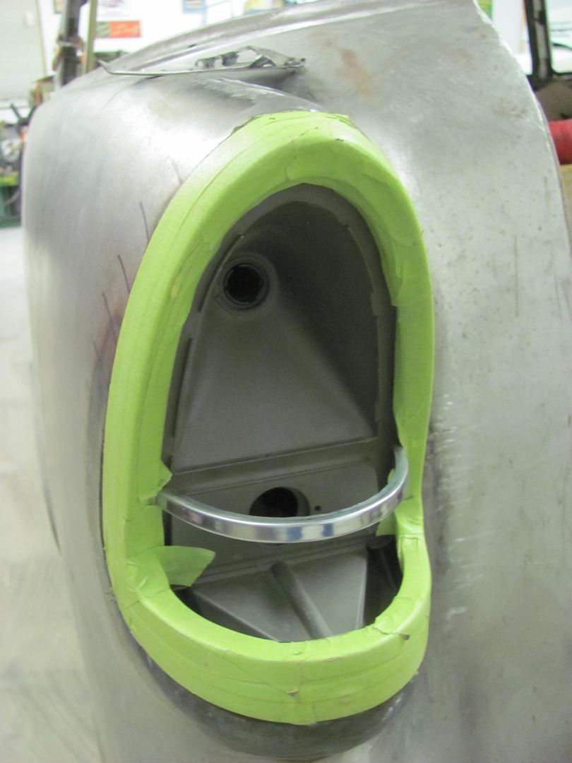
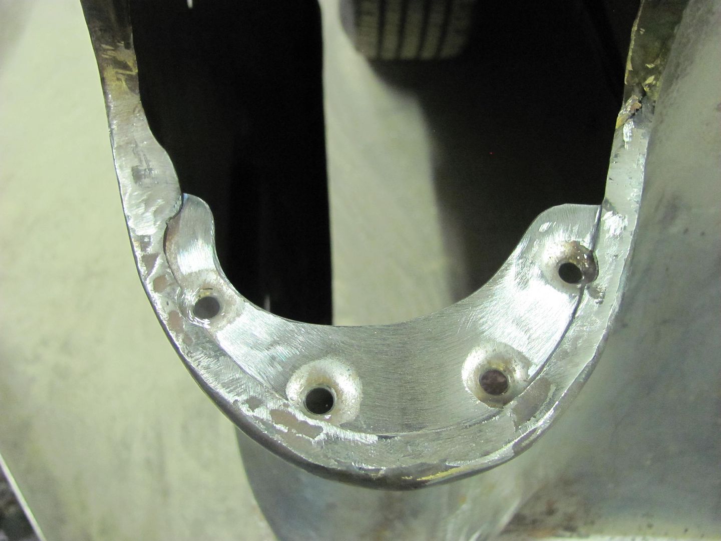
That worked fairly well, so it was clamped in place and a transfer punch used to mark the housing for drilling mounting holes..
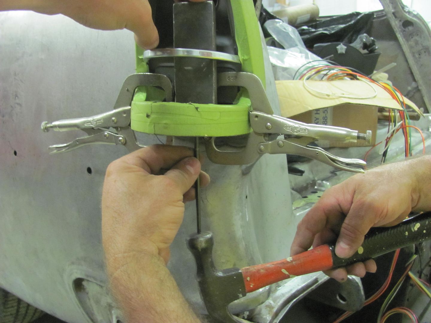
Then the holes were slightly slotted using a dremel for side to side adjustability. Here's the results, from different views....
https://youtu.be/848V2PbuQJw
https://youtu.be/N_Qz0NZxh5g
https://youtu.be/PVeWQyb35j8
OK, now for the bad that we found with the kit... The original lamp housing must be removed for clearance, and a new (included) one gets installed below the original position. The new housing has those spring loaded contacts that some tend to bend over and short out, so I gave the wires a couple gentle tugs to see if the contacts deflected toward the outside shell...
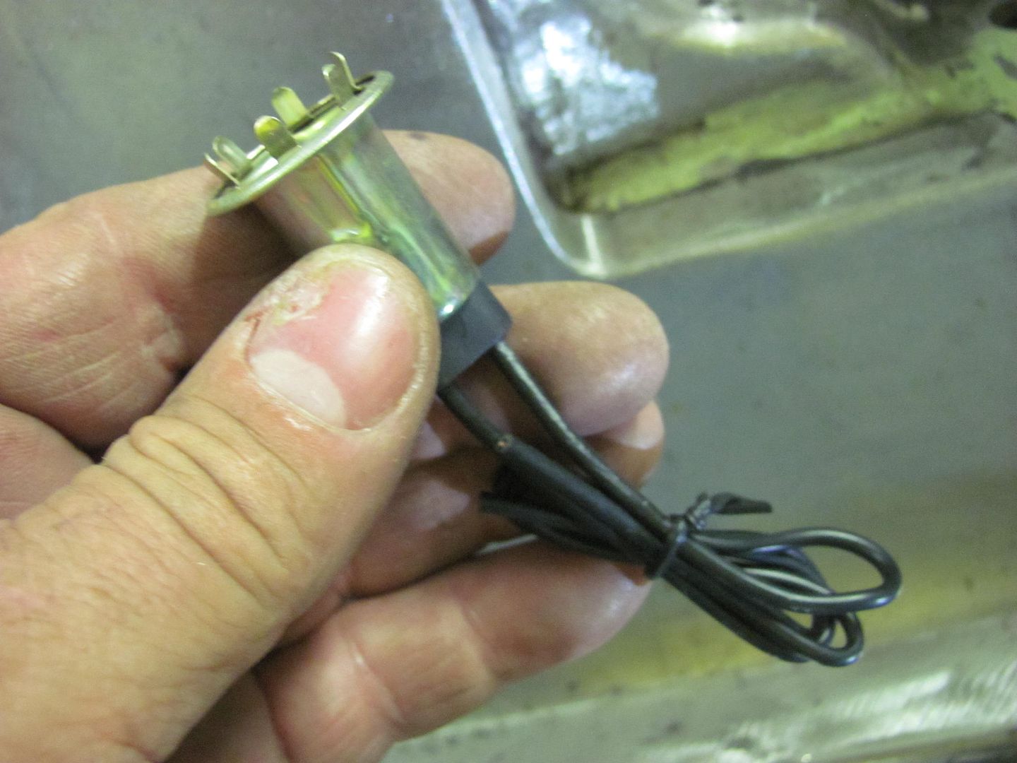
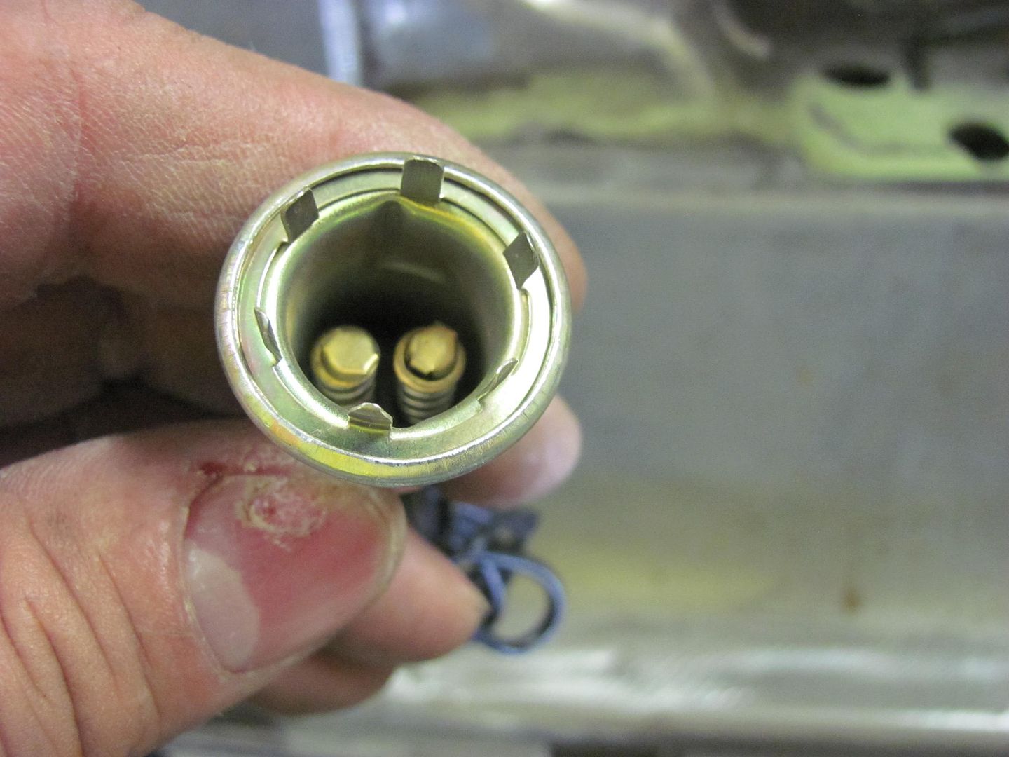
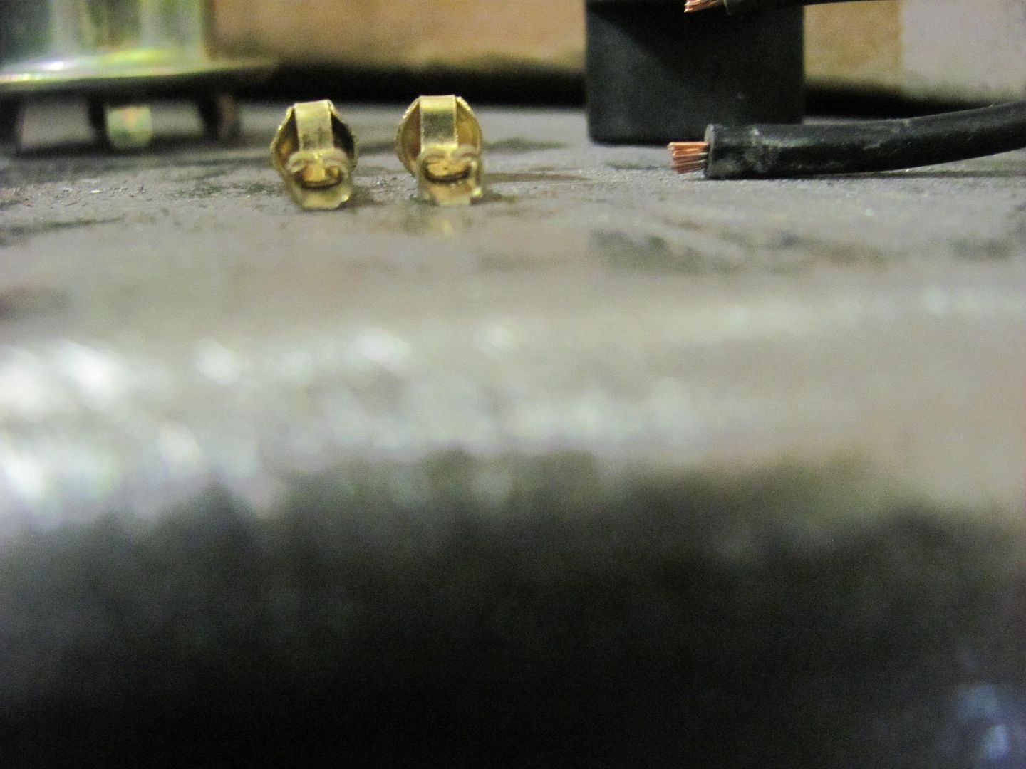
Surprise, surprise, the contacts pulled clean off....
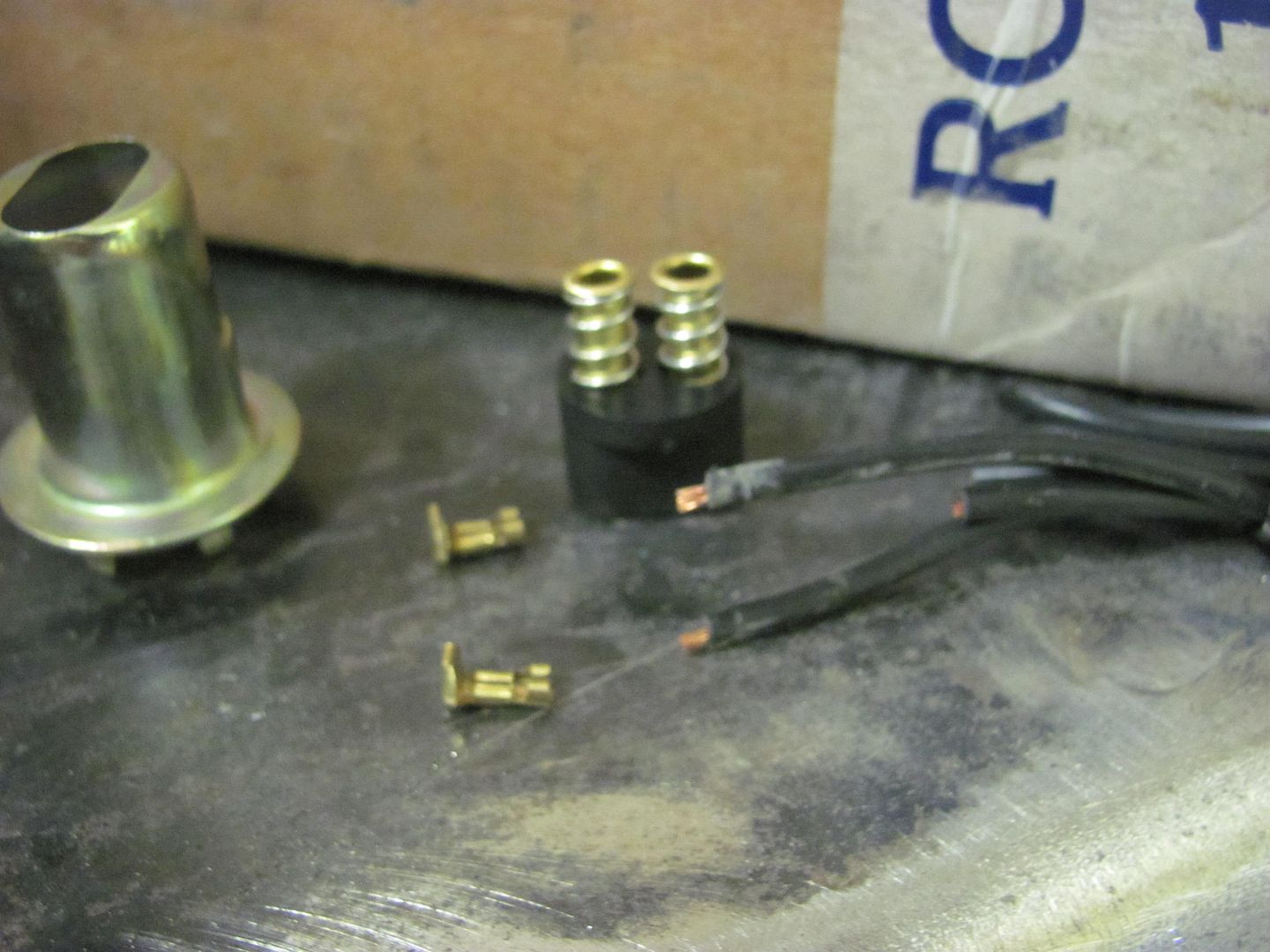
Note there is no copper inside the contacts, indicating these had a loose crimp...
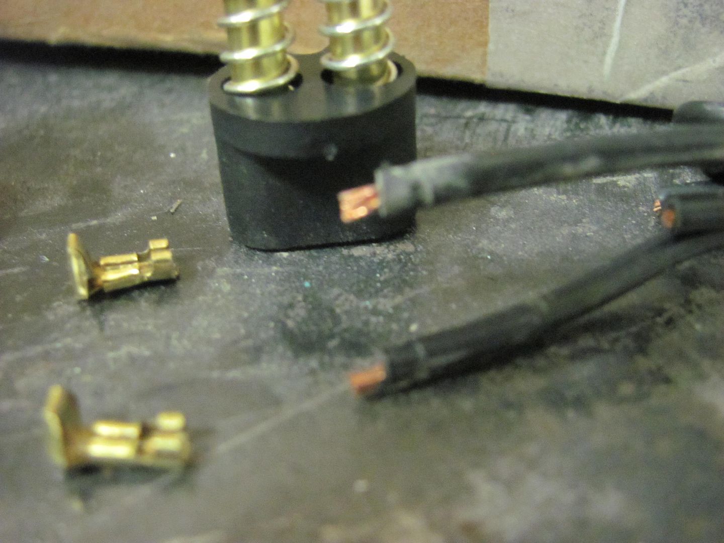
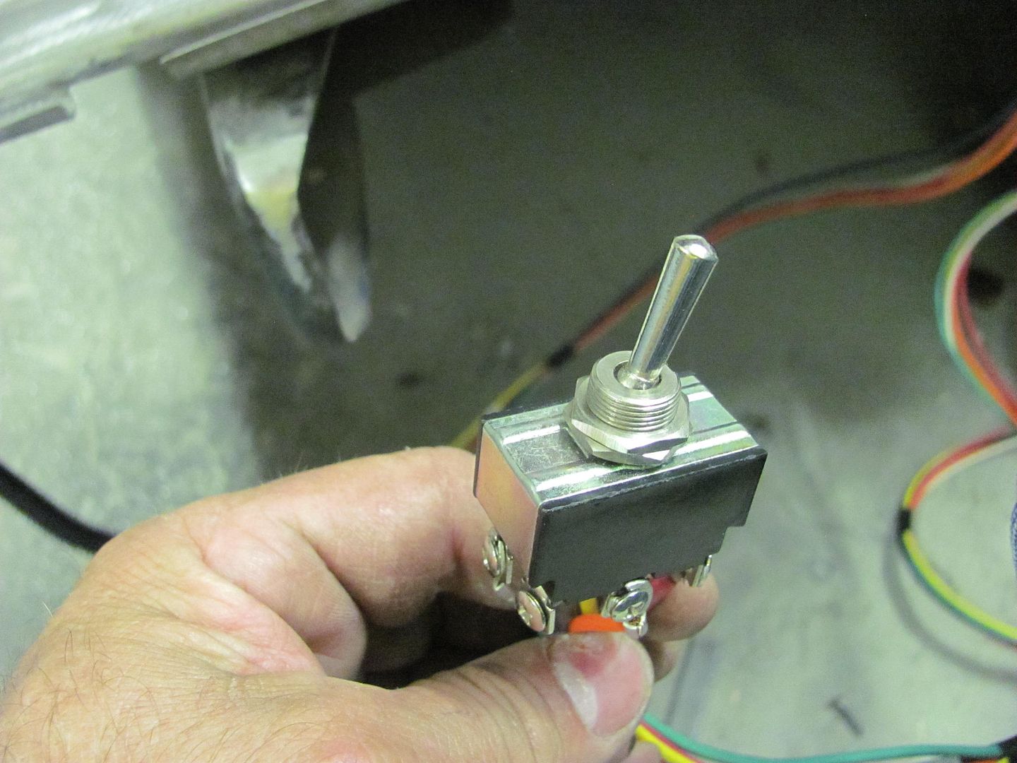
Next, the operation of the motor function seemed to be intermittent. A recheck of the power connections showed no issues, so we pressed a bit harder on the switches toggle, and the function returned. Multiple repeat attempts were performed and the switch proved to be the culprit. It appears to be a cheapo switch that has intermittent contact function. So looks like we'll be replacing a couple of the parts for this kit... So much for everything you need in one package....
Worked on the Rocky Hinge hidden fuel door this evening. The mounting plate we made is plug welded to the tail light opening..
Slight trimming needed.....
Then some 3M body molding adhesive tape is added to the top of the pivot bracket and the lens pressed in place. Here's the initial test...
https://youtu.be/oZ6JYr988dc
That worked fairly well, so it was clamped in place and a transfer punch used to mark the housing for drilling mounting holes..
Then the holes were slightly slotted using a dremel for side to side adjustability. Here's the results, from different views....
https://youtu.be/848V2PbuQJw
https://youtu.be/N_Qz0NZxh5g
https://youtu.be/PVeWQyb35j8
OK, now for the bad that we found with the kit... The original lamp housing must be removed for clearance, and a new (included) one gets installed below the original position. The new housing has those spring loaded contacts that some tend to bend over and short out, so I gave the wires a couple gentle tugs to see if the contacts deflected toward the outside shell...
Surprise, surprise, the contacts pulled clean off....
Note there is no copper inside the contacts, indicating these had a loose crimp...
Next, the operation of the motor function seemed to be intermittent. A recheck of the power connections showed no issues, so we pressed a bit harder on the switches toggle, and the function returned. Multiple repeat attempts were performed and the switch proved to be the culprit. It appears to be a cheapo switch that has intermittent contact function. So looks like we'll be replacing a couple of the parts for this kit... So much for everything you need in one package....
Chateau Slate 66
Well-known member
As you know, quality control is quite uncommon these days. The good news is you probably won't be trying to hunt down these "small" problems after final assembly when it can quickly turn into a "big" problem.
36racin
Active member
Absolutely amazing attention to detail. I have wondered, casually, whether your Chevy or Don Long's Corvette gets color applied first. That's a close race!
Am I missing another thread like this one somewhere?? If so please post a link
wbrian63
Well-known member
I feel your pain regarding quality. I recently refubished an old utility trailer I had for my brother to use. It originally was just an open side affair with a end gate formed by 2 2x8's stacked in a channel. I closed the sides in and made a swing-down tail gate made up of 1-1/2" square tube mitered at the corners with integral non-removable slide bolts for the latches.
I hemmed and hawed about where to install the license plate and finally settled on the tail gate, which revealed the problem of how to provide power to the lights that illuminate the plate.
As part of the rework, I took the time to route all of the wiring for the lamps on the trailer through 1/2" square tube. I wasn't going to cave at this point and run wires on the surface of the tailgate, so I drilled some access holes and routed the wires through the frame of the tailgate. Welded the holes up after the work was done.
The tailgate is removable, so I picked up a simple polarized connector on Amazon, just like this one: http://www.amazon.com/gp/product/B006ZOLDJ2/?tag=atomicindus08-20
Got everything wired together and all the lamps worked perfectly, except for those on the tailgate. I validated that I had 12v at the positive pin on the trailer-side of the connector, so the problem must be in either the connections to the lights, right?
Pulled everything apart and checked the solder joints, etc. - found nothing wrong.
Snaked the wire out of the tube. Nothing wrong.
Finally checked the tailgate side of the plug - no connection whatsoever from either pin through to the wires....
grrrr.... took nearly an hour to snake the wires back into the frame of the tailgate - without the aid of the access holes, it was a royal PITA.
took all of 1 minute to cut the bad end off the wiring harness and replace it with a working unit...
Thanks for the comments and discussion guys...
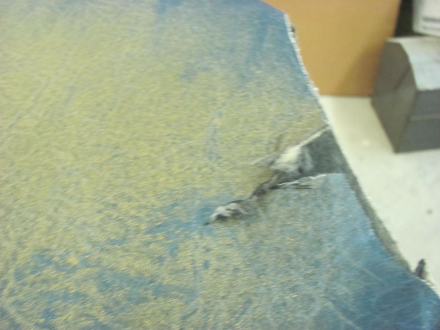
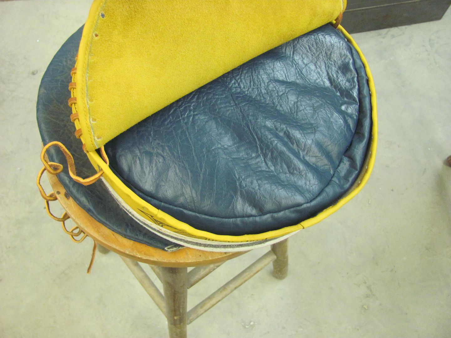
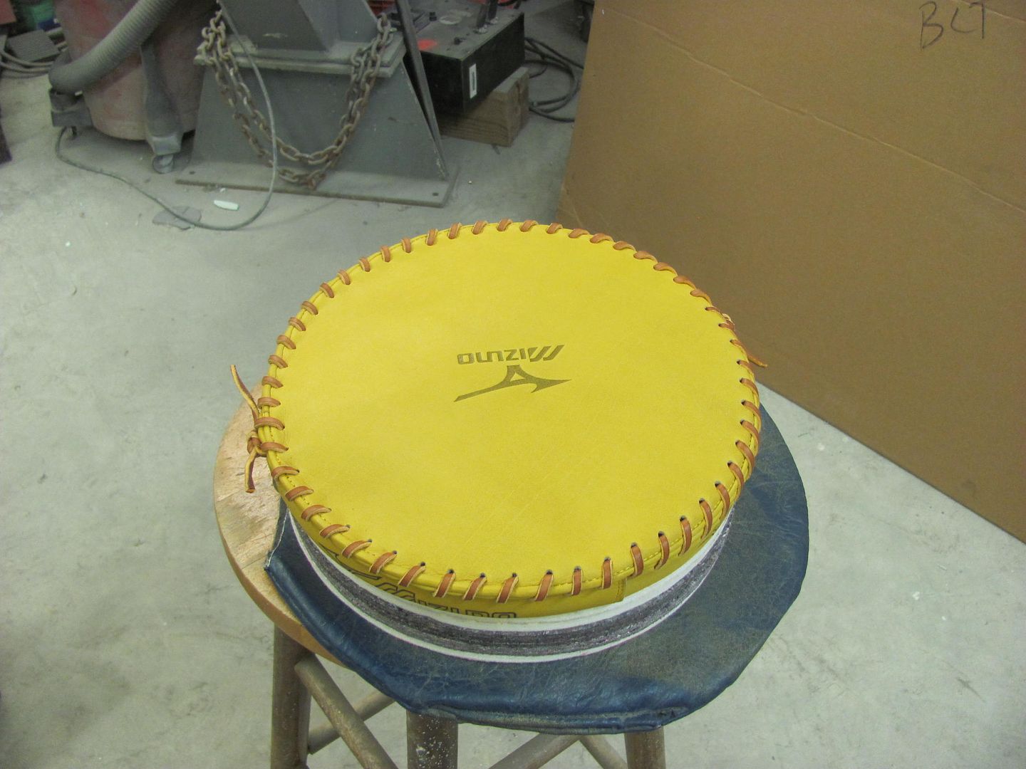
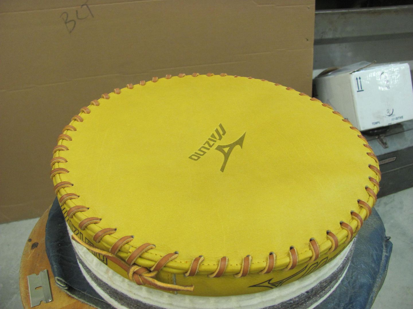
Recently I took delivery of a ball glove pounding pad, $39 on Amazon per a link posted by Johnny Arial on AllMetalShaping. It was very light, and where I did not give it a go with a sheet metal test sample, something in me wanted to see what was inside the bag. So here we go, can't leave well enough alone...
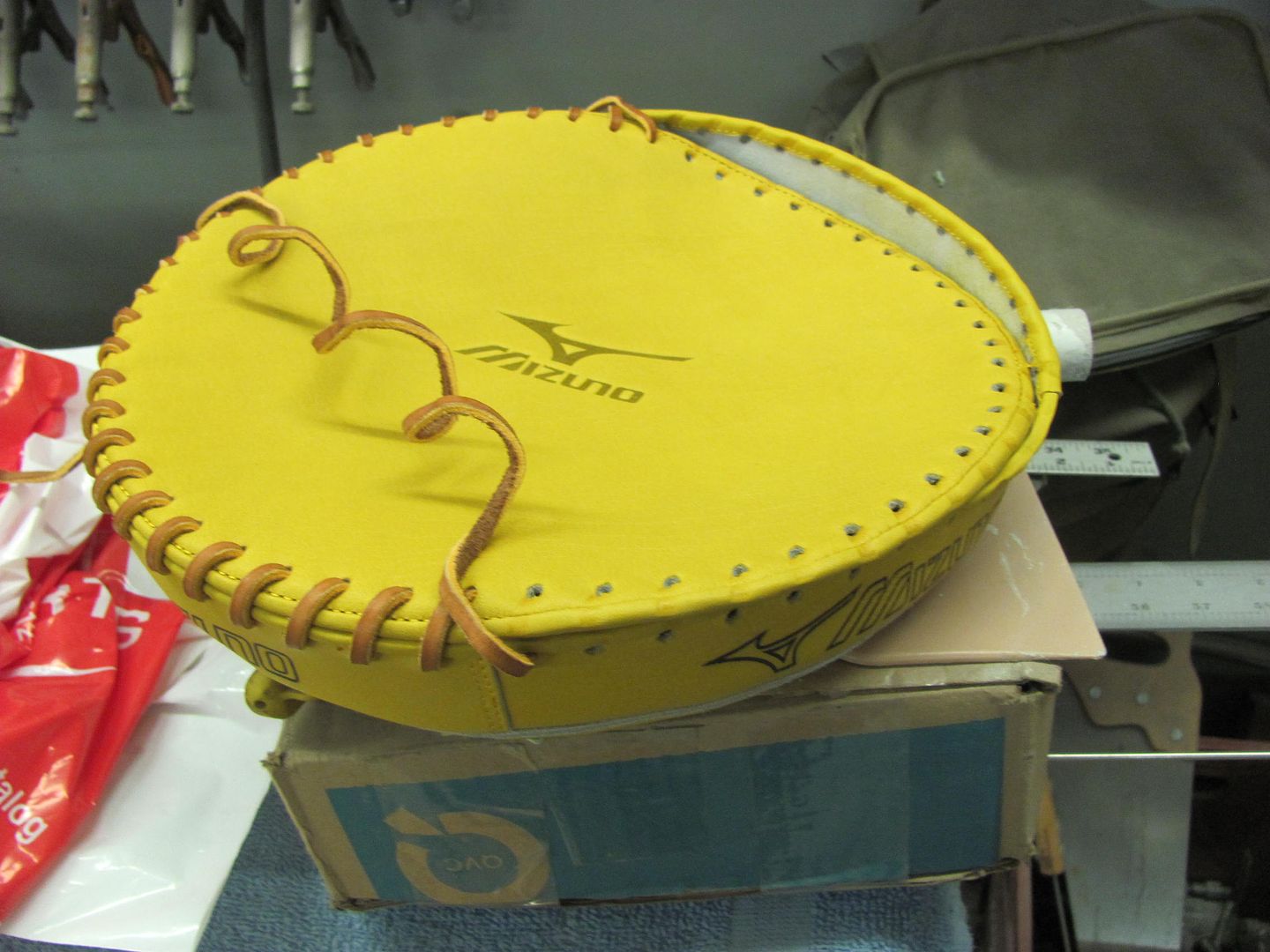
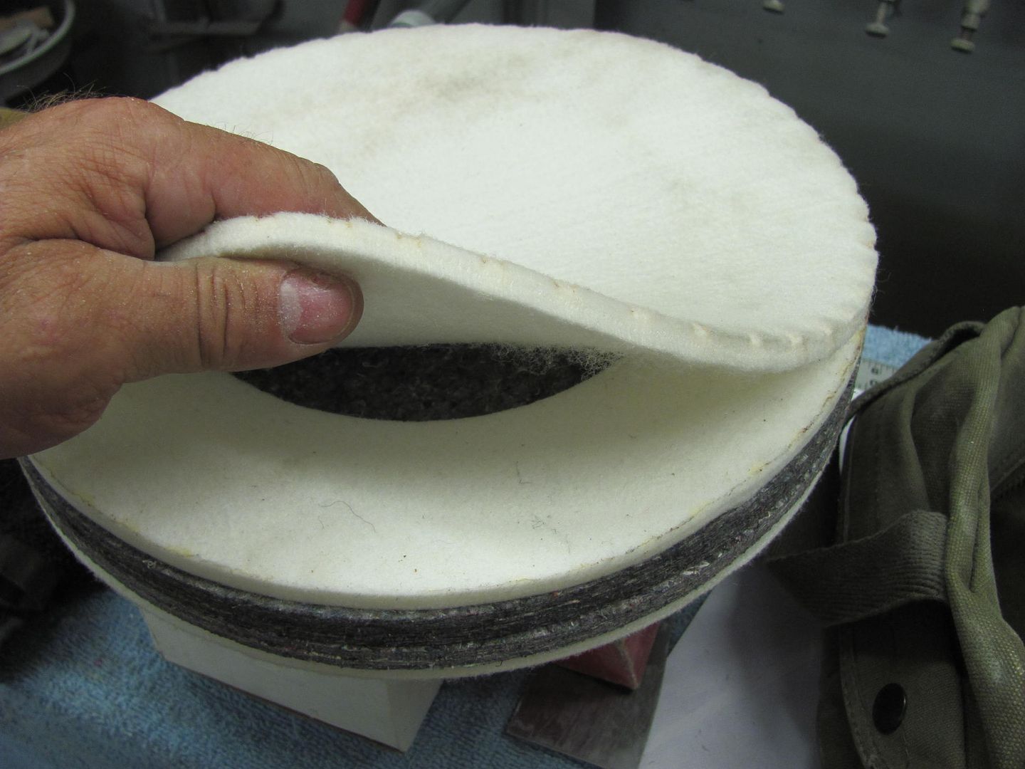
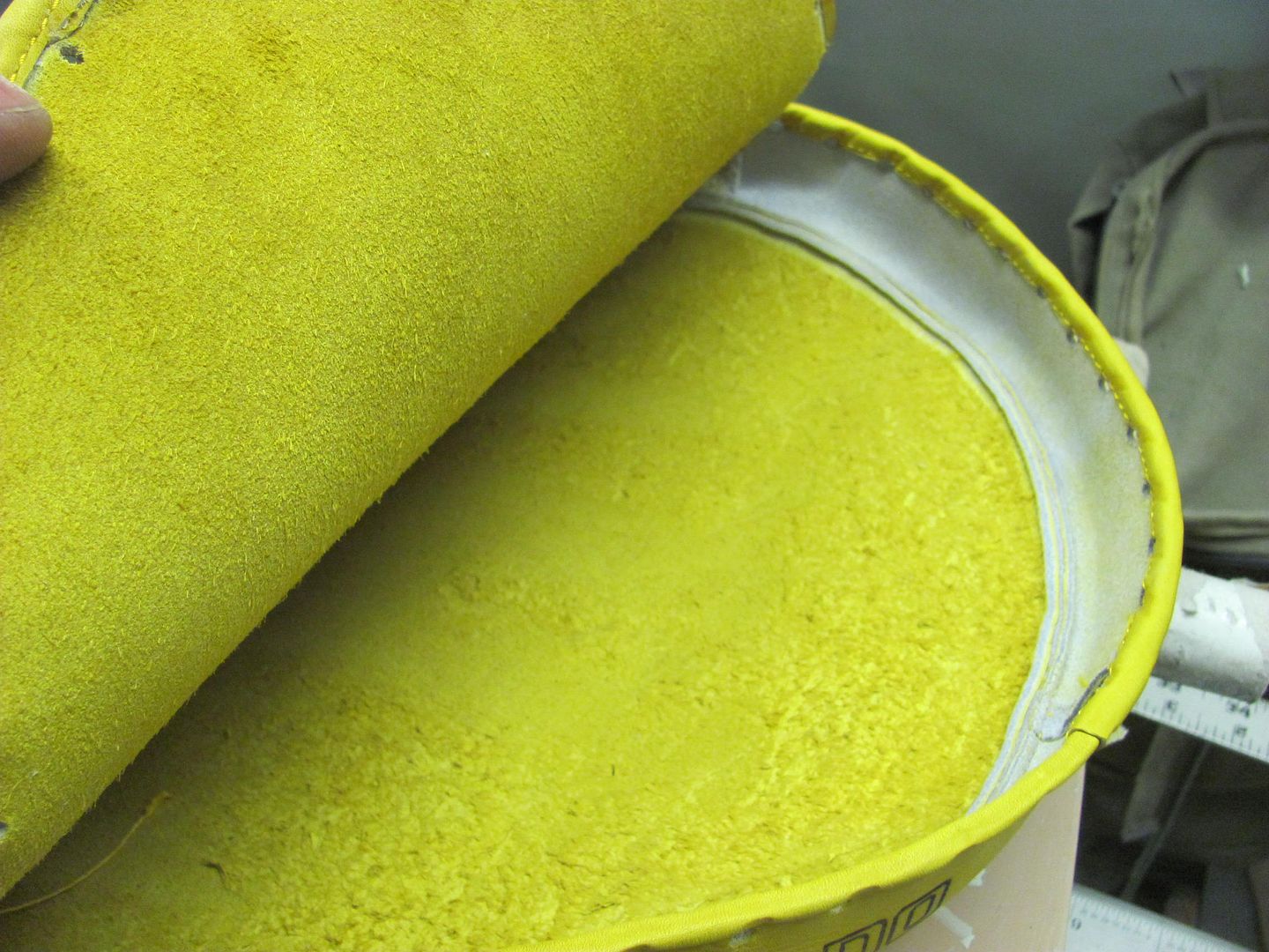
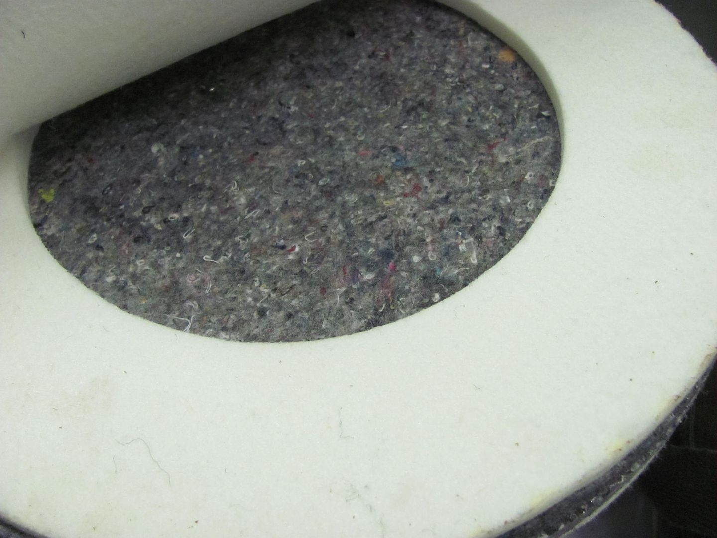
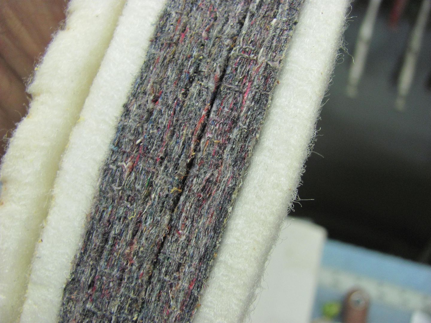
Looks like a high density felt pad...
My previous shot bag had become a casualty inside of a quarter panel when using it as a dolly... It found a sharp piece of metal which caused the tear... and I caused the cut so I could empty it out and pull it out of the cavity it was in.. It had approx. 50 lbs or better of lead shot in it at the time, and for some reason I didn't think about removal when I was dropping it in the hole.
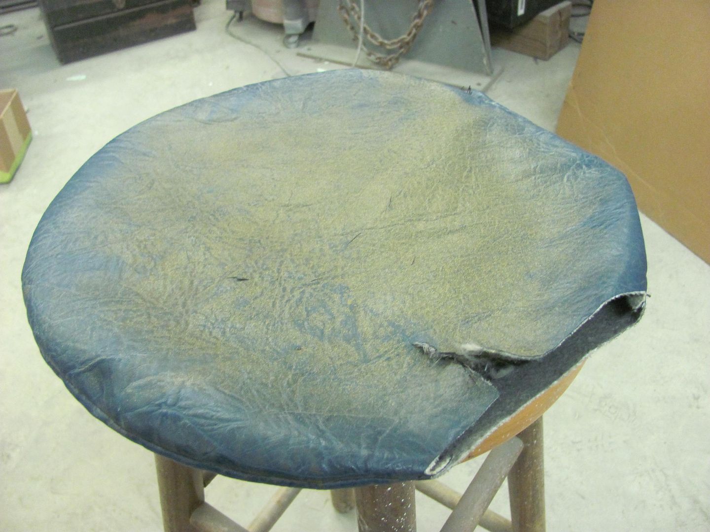
So I had put in an order last night for another bus seat cover (Kevlar material) and took it today with all the pieces to Anthony's Upholstery. This one is a bit smaller, so also more manageable. I think I had about 1/3 of the 50 lbs left over, so may have to make another smaller shot bag..
Comparison, the old to the new one..
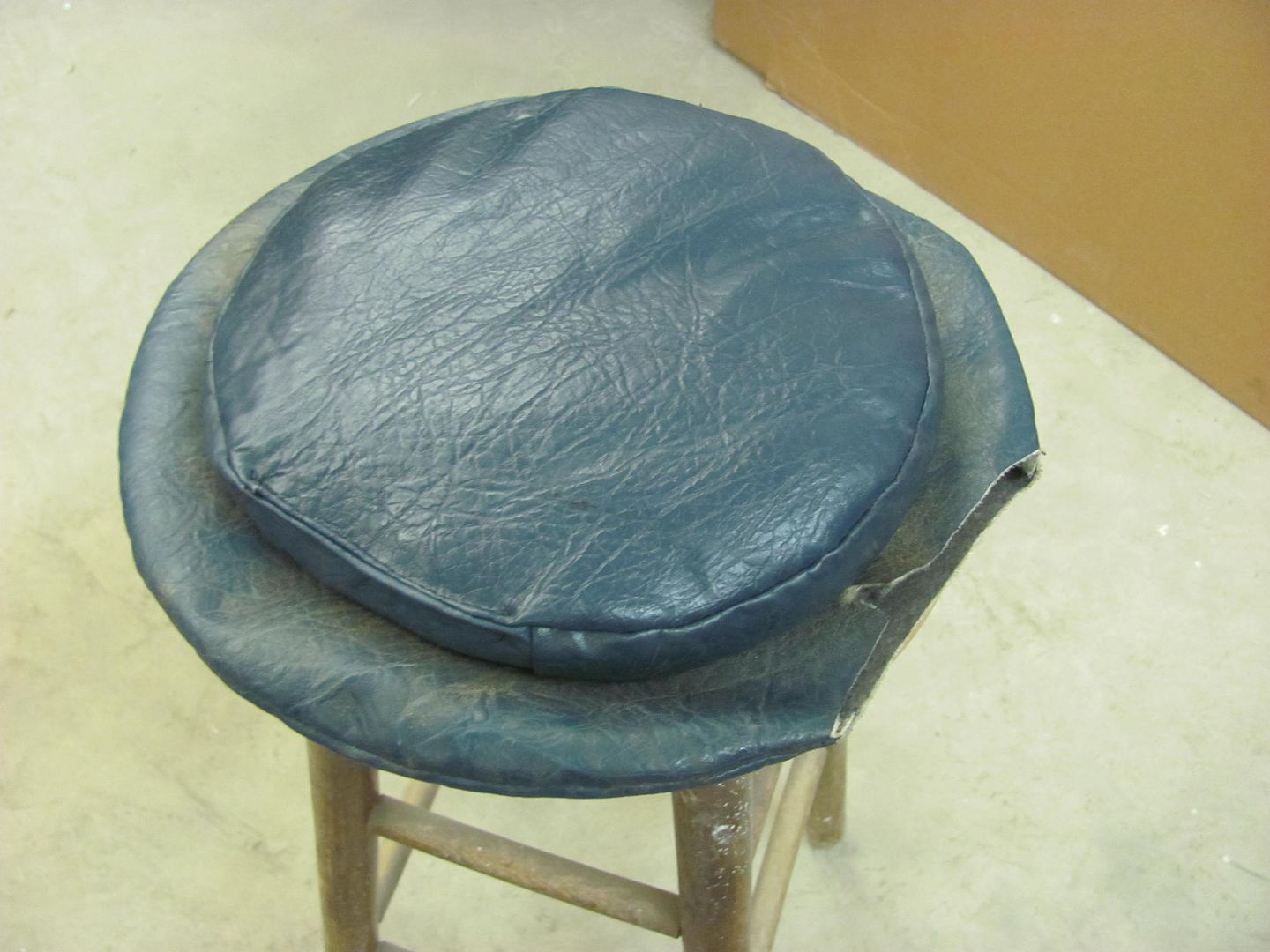
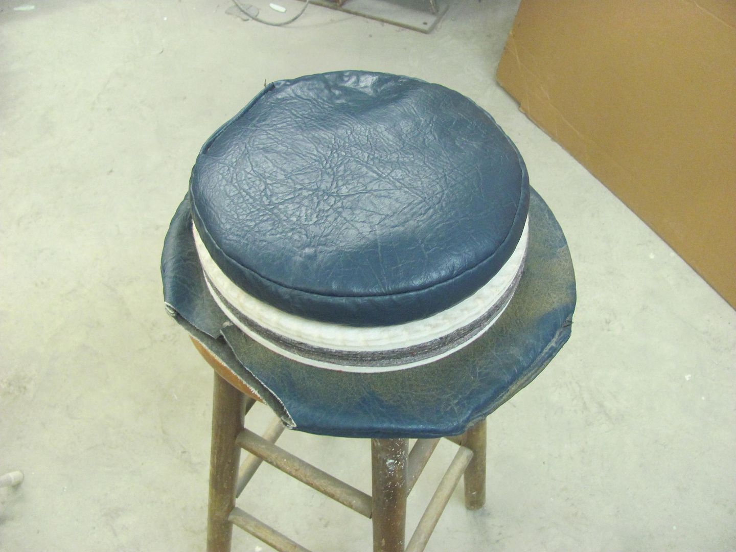
Something told me when that Amazon order was placed that this thing would have lead shot inside before all was said and done.. It does make a nice shot bag, and has a nice look.
Recently I took delivery of a ball glove pounding pad, $39 on Amazon per a link posted by Johnny Arial on AllMetalShaping. It was very light, and where I did not give it a go with a sheet metal test sample, something in me wanted to see what was inside the bag. So here we go, can't leave well enough alone...
Looks like a high density felt pad...
My previous shot bag had become a casualty inside of a quarter panel when using it as a dolly... It found a sharp piece of metal which caused the tear... and I caused the cut so I could empty it out and pull it out of the cavity it was in.. It had approx. 50 lbs or better of lead shot in it at the time, and for some reason I didn't think about removal when I was dropping it in the hole.
So I had put in an order last night for another bus seat cover (Kevlar material) and took it today with all the pieces to Anthony's Upholstery. This one is a bit smaller, so also more manageable. I think I had about 1/3 of the 50 lbs left over, so may have to make another smaller shot bag..
Comparison, the old to the new one..
Something told me when that Amazon order was placed that this thing would have lead shot inside before all was said and done.. It does make a nice shot bag, and has a nice look.
Ohmthis
Well-known member
What did you not like about the felt? I can see the lead giving a more contour, but trying to learn a little. Also, do you prefer lead to sand? Why? Thanks!
The felt gave a very firm support with no ability to "manipulate" the shape of the void. With the shot bag it has just enough looseness in the fill that a couple of fist punches and you have a nice void to work with.. So a shot bag is more readily changed to fit the shape of the object you are hammering.
Ohmthis
Well-known member
Robert, thanks for the explanation. Great work also!
don long
Well-known member
Absolutely amazing attention to detail. I have wondered, casually, whether your Chevy or Don Long's Corvette gets color applied first. That's a close race!
My money's on Don.....
Thanks for that vote of confidence Robert, But don't put any money on that!!
I am starting to put the car together to work out all the bugs prior to painting.
And I keep coming up with new things I want to add to the car like power windows, antenna and hood actuators to list a few. So It will be a while before the color hits the vette
Happy Fathers Day
nonhog
Well-known member
Was hoping for a review on that sport bag. Got one yesterday for fathers day.
I think you could use it in much the same fashion as a hollow in a stump, but it does have a severely limited depth. I just see more adaptability with it having the shot filler..
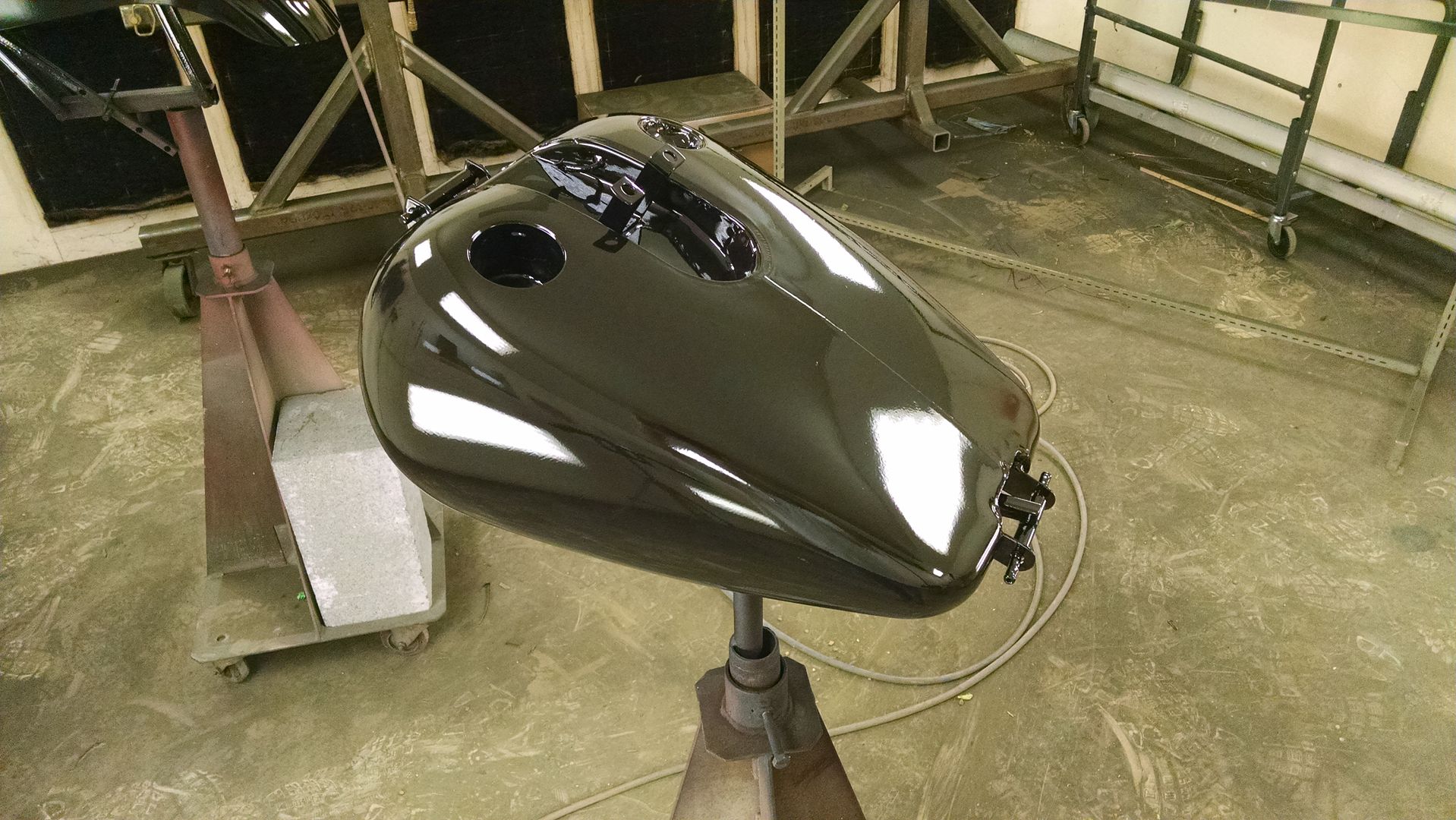
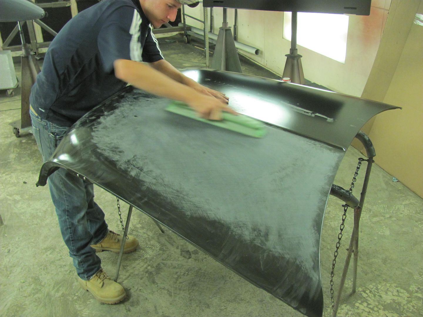
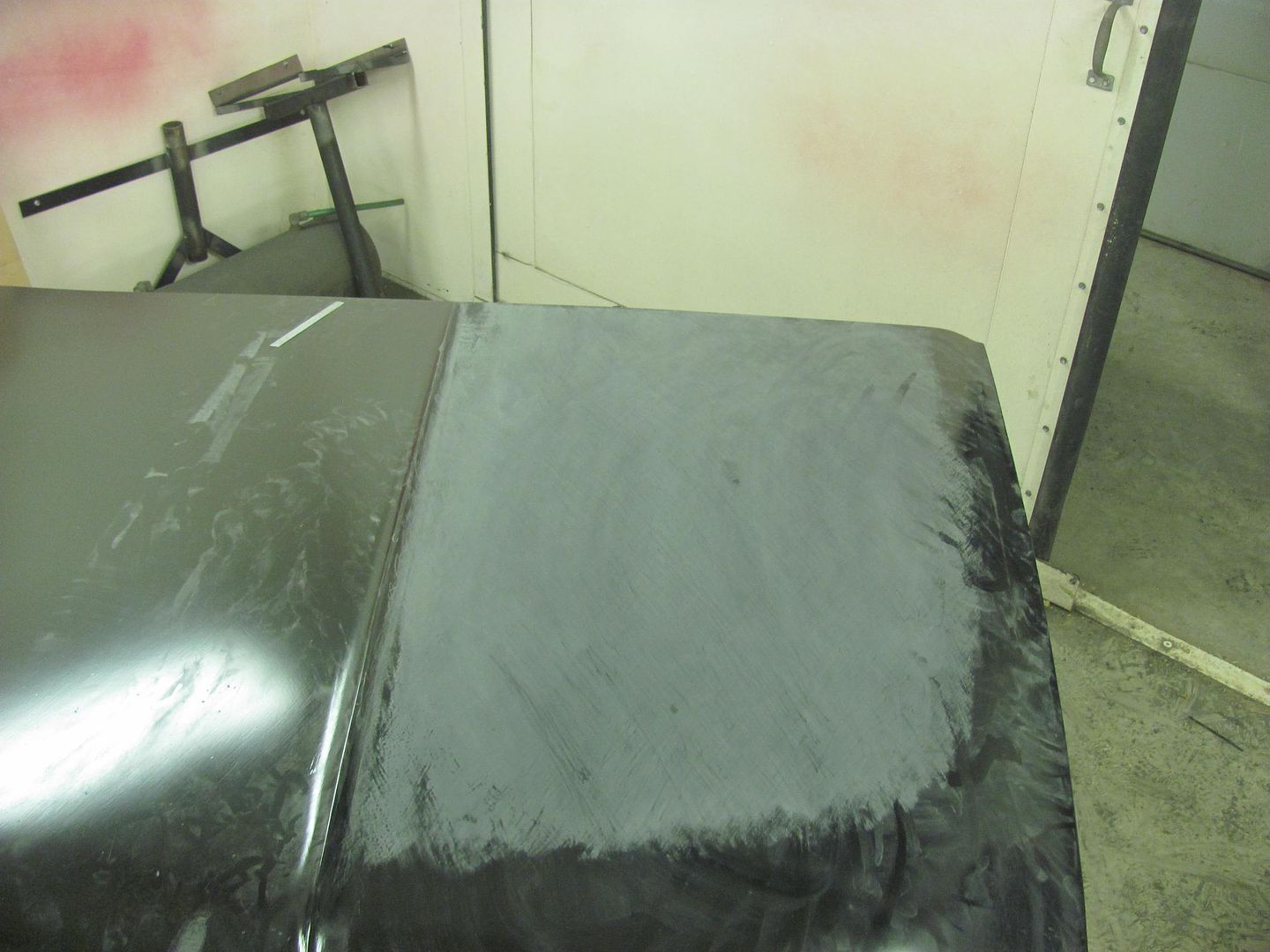
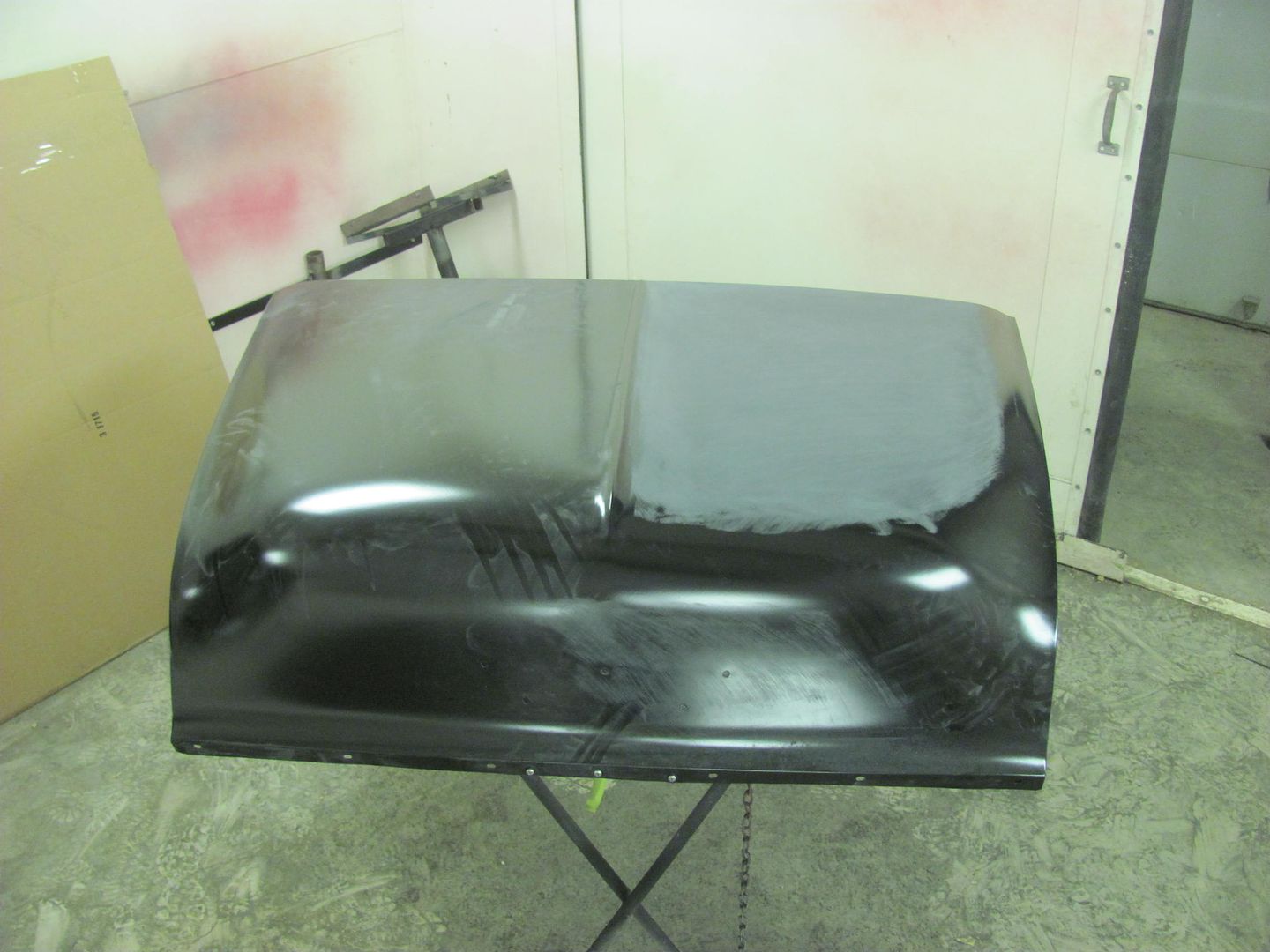
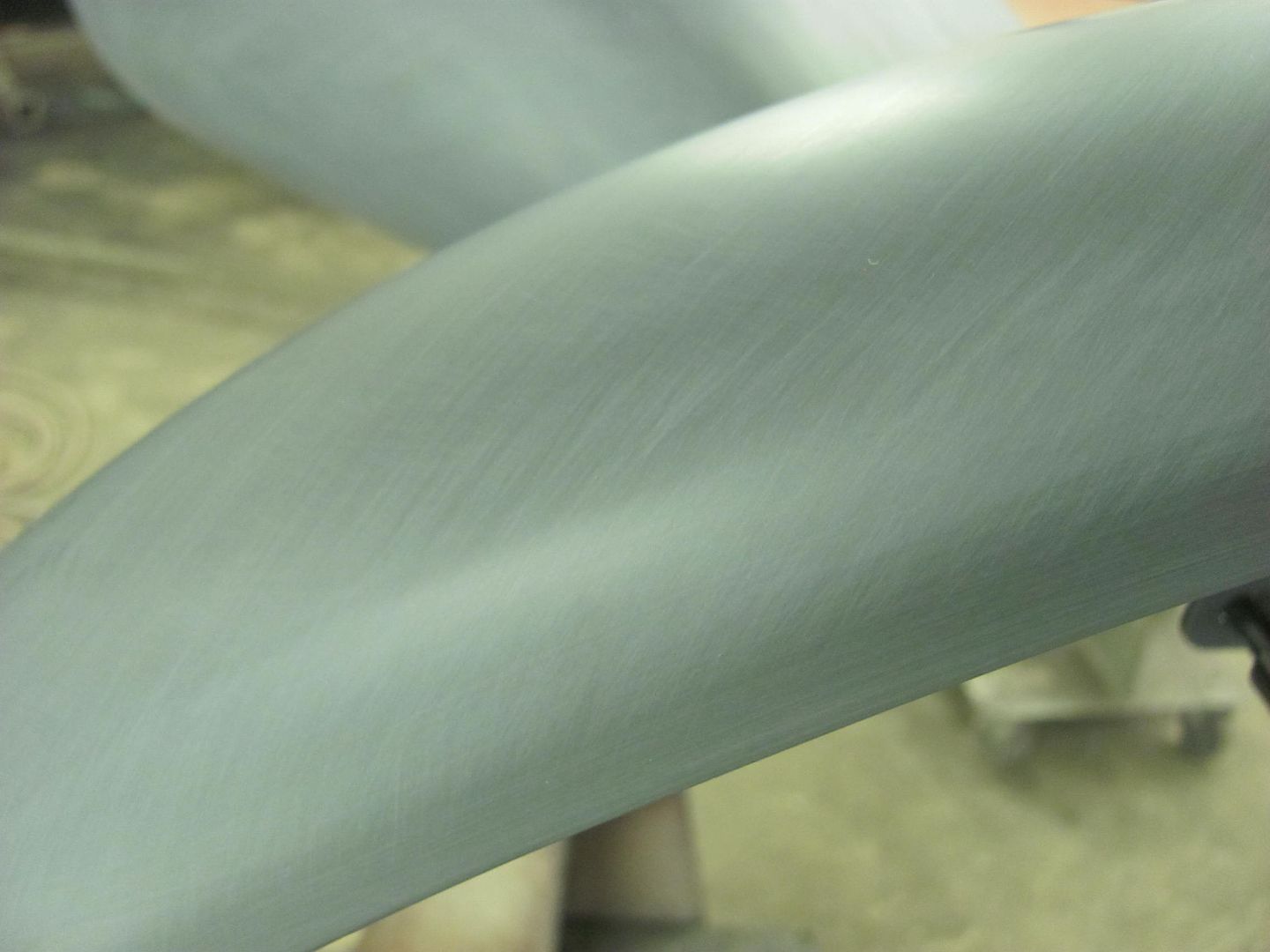
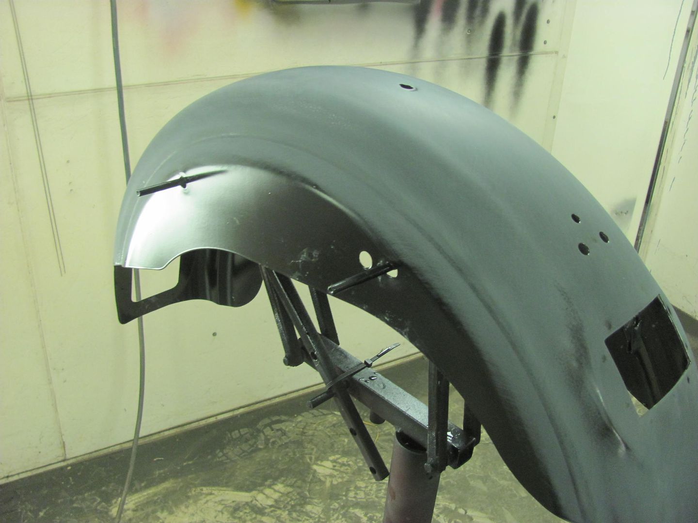
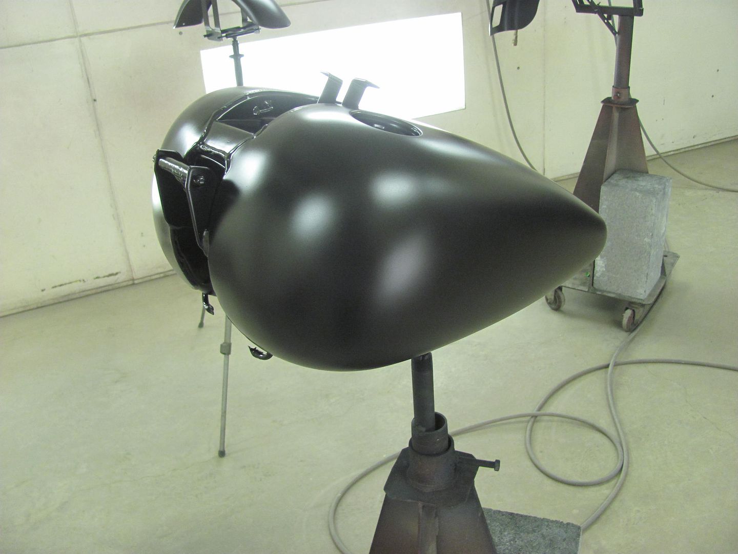
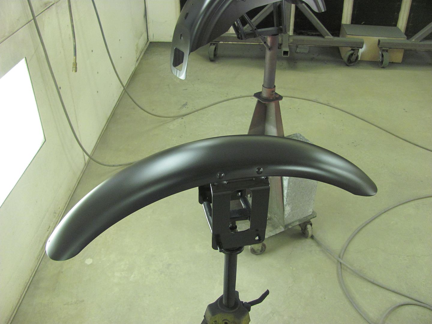
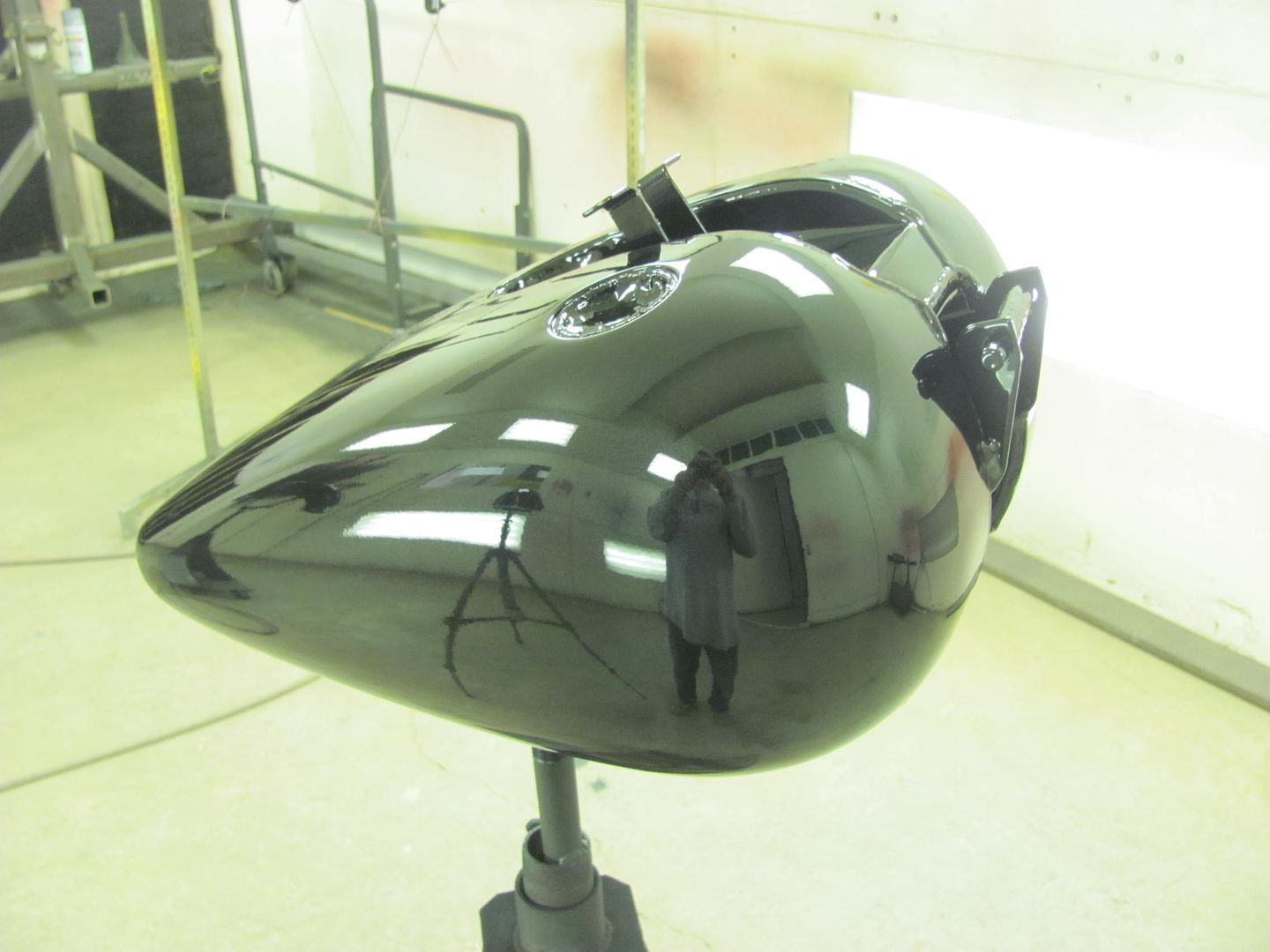
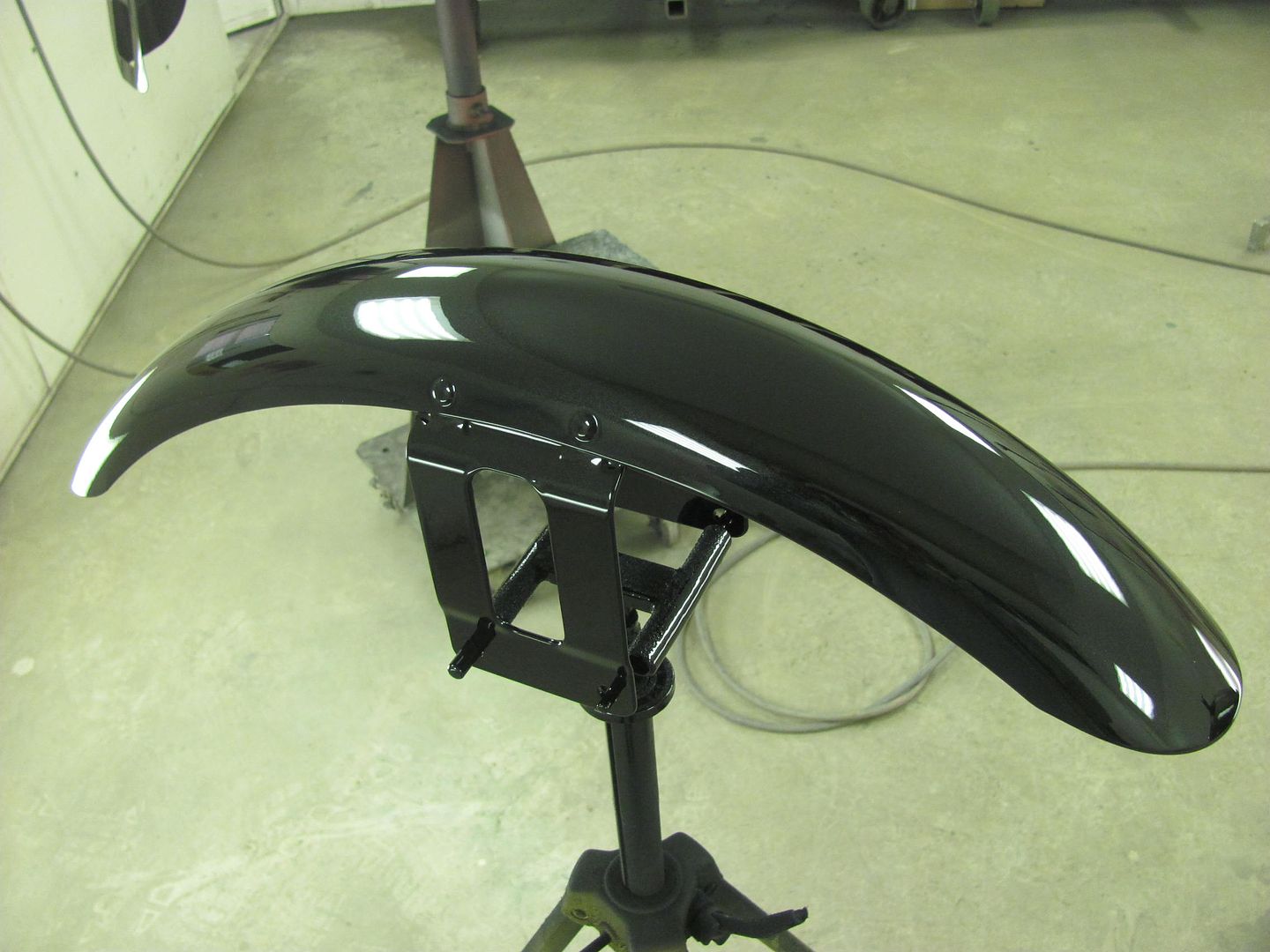
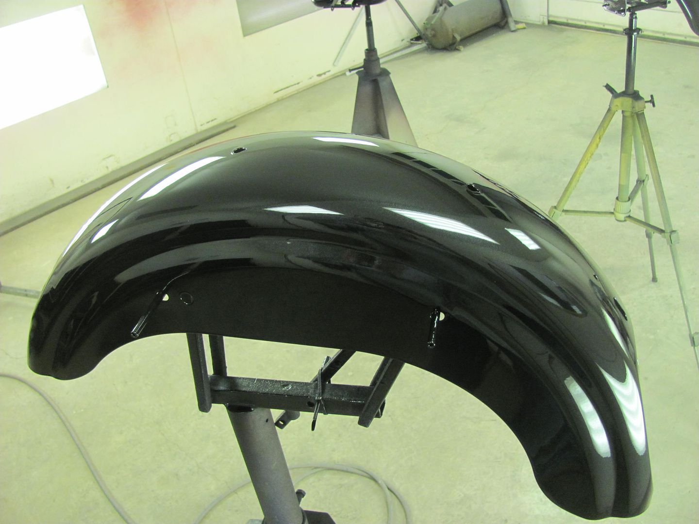
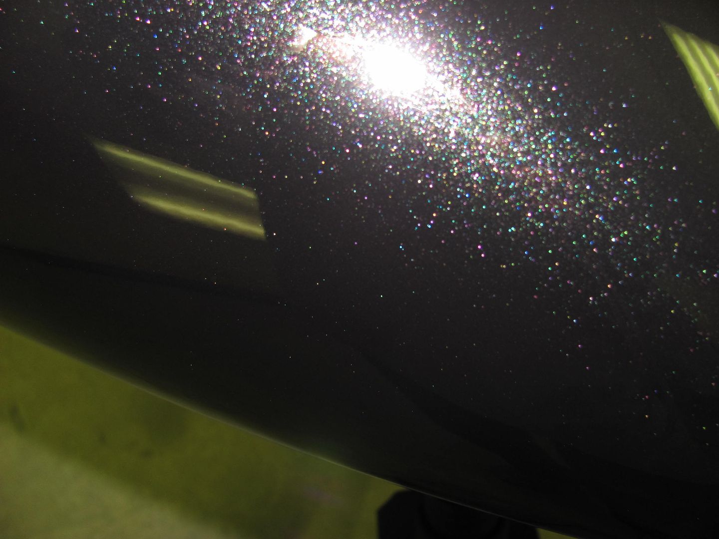
More progress on the wagon, got some SPI epoxy sprayed, hopefully this will wet sand out and be ready for BC/CC.
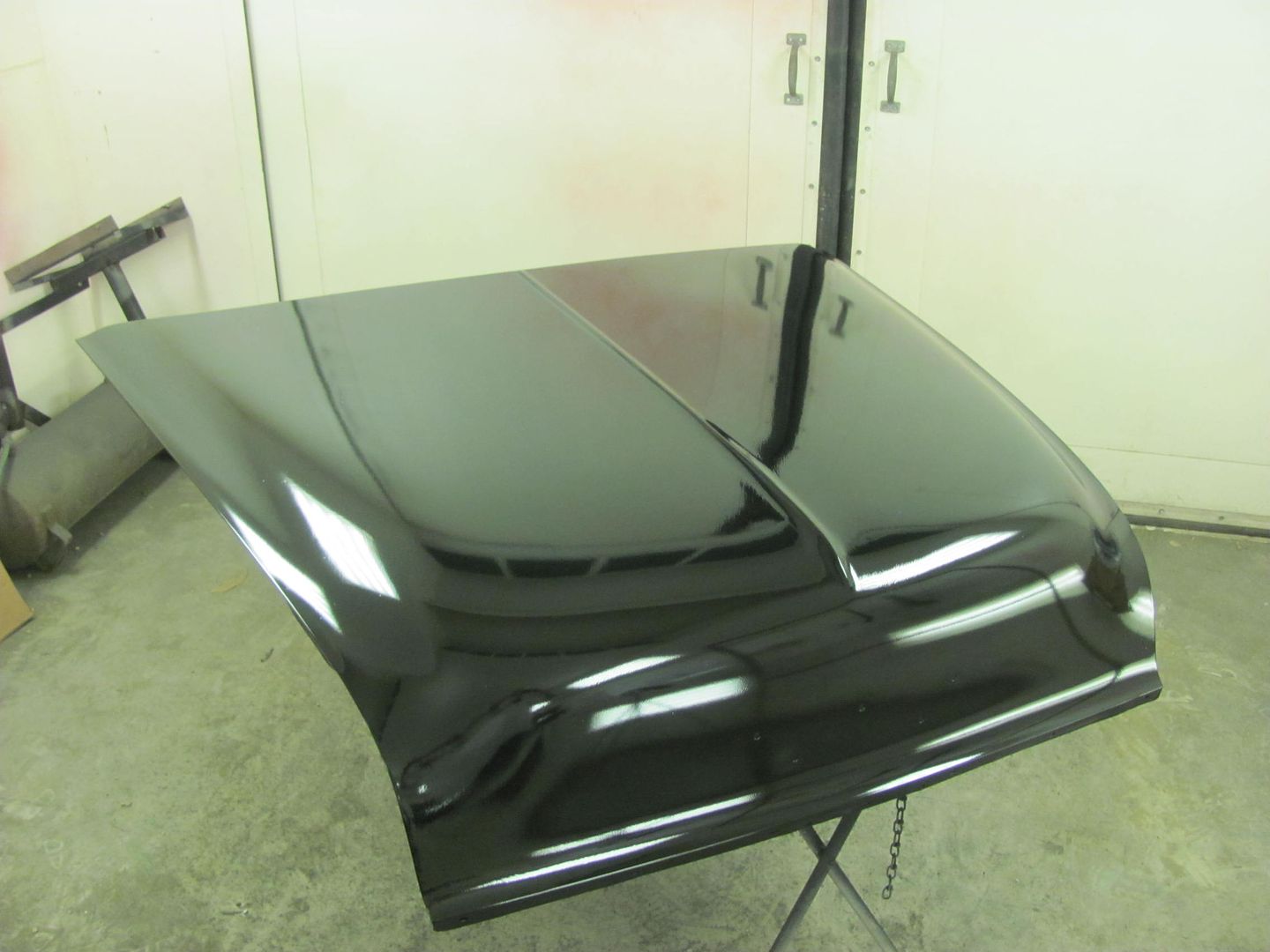
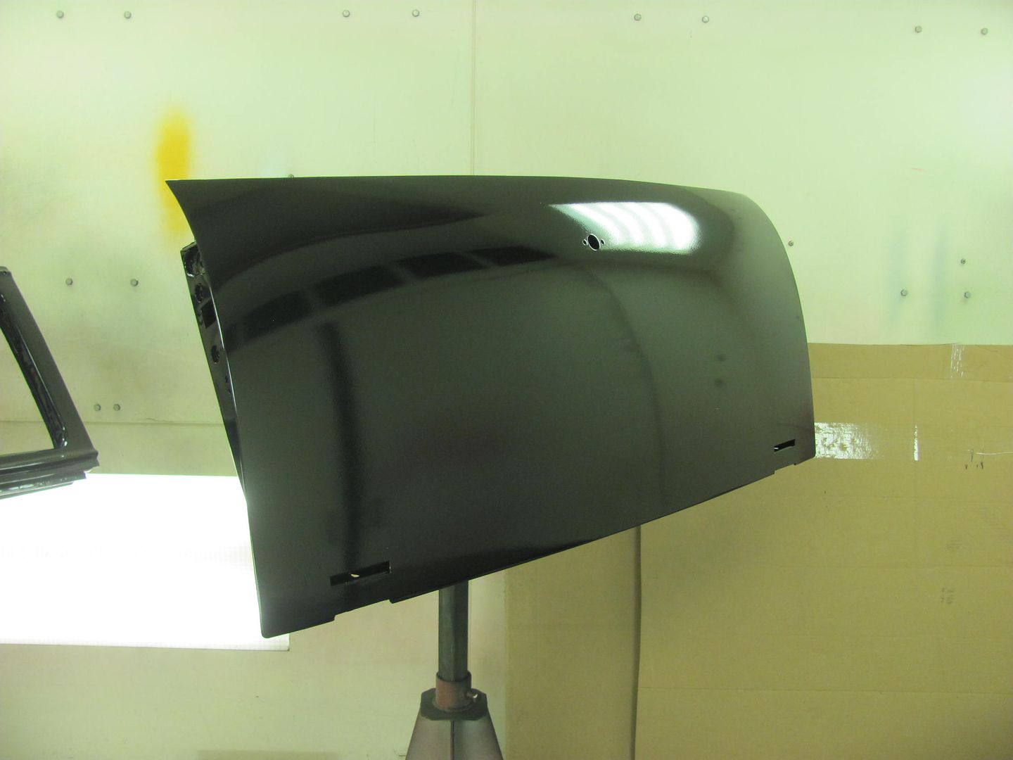
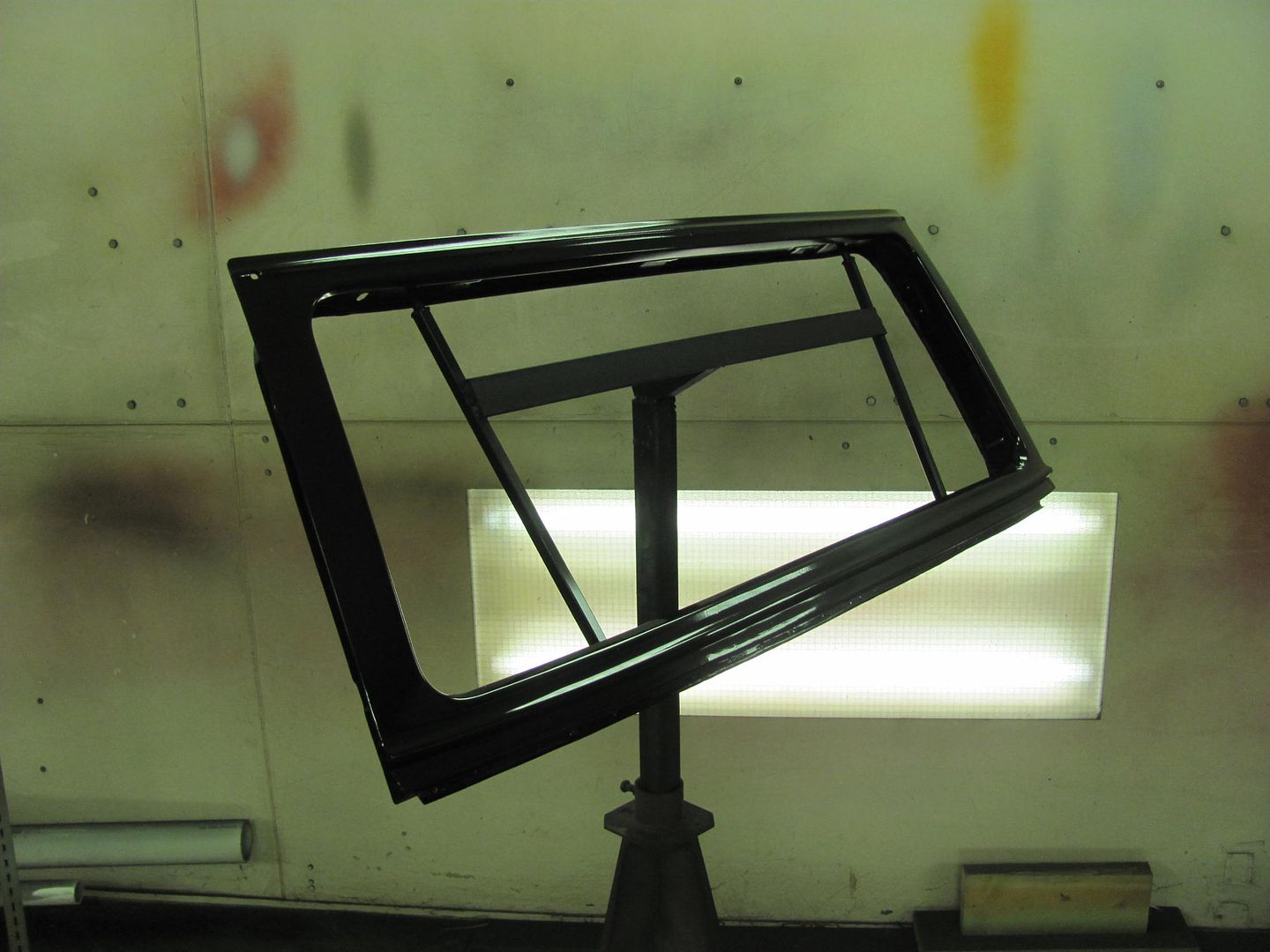
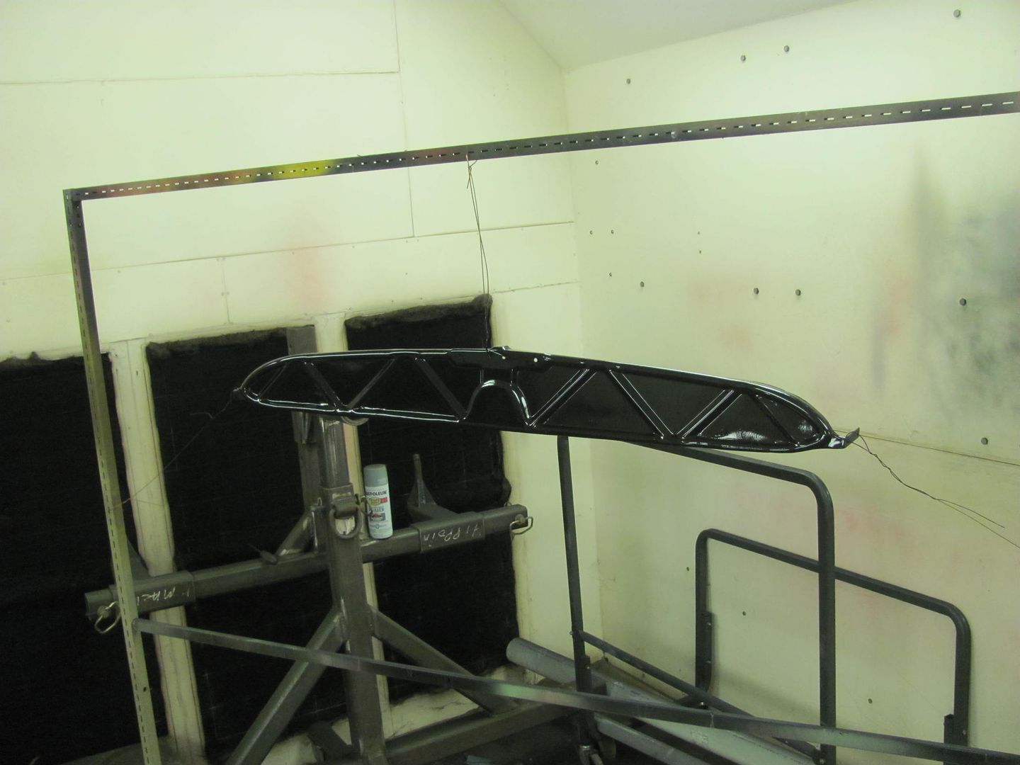
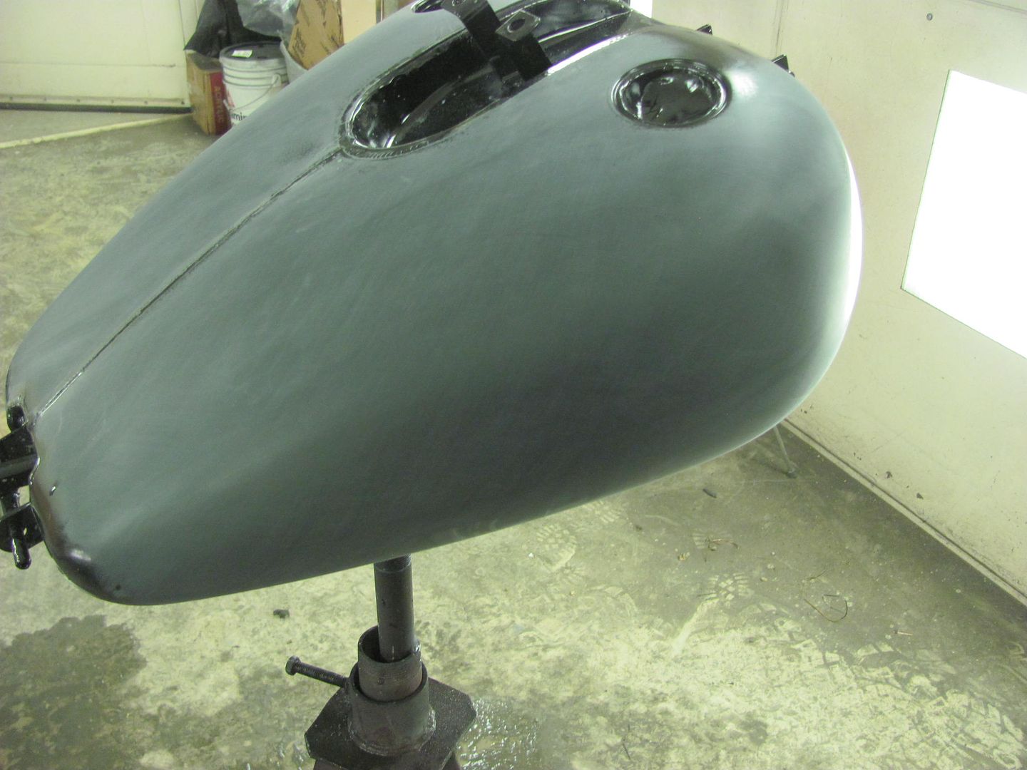
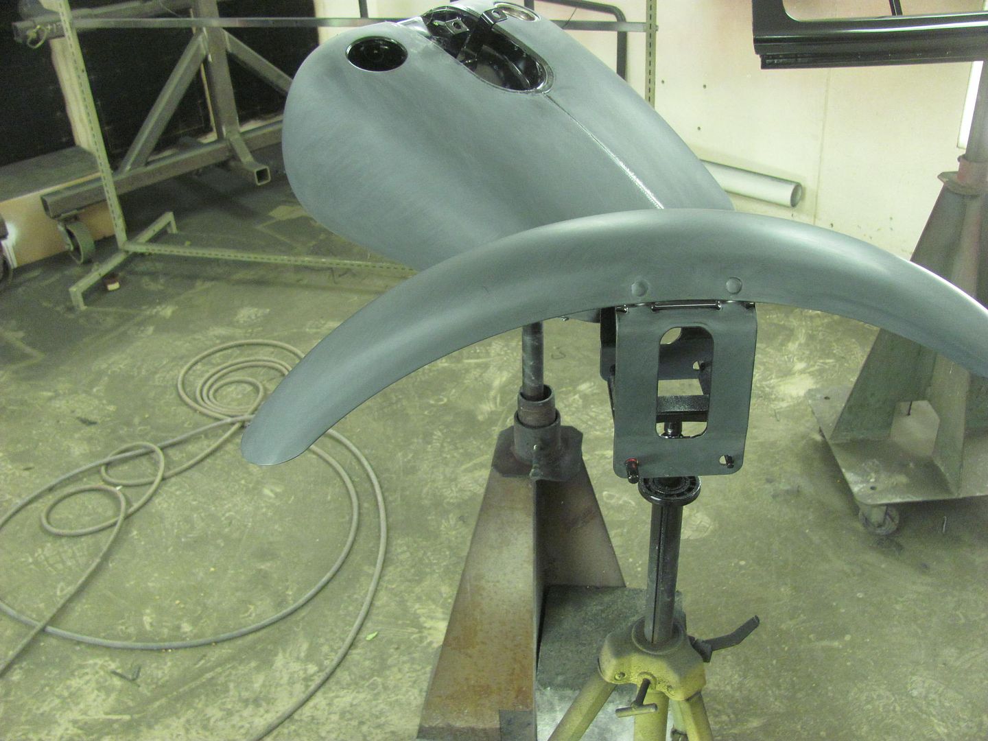
Also got some primer on the sheetmetal for an 01 Dyna
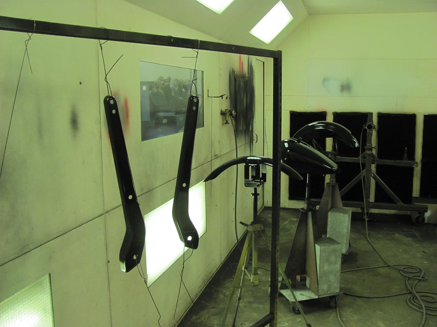
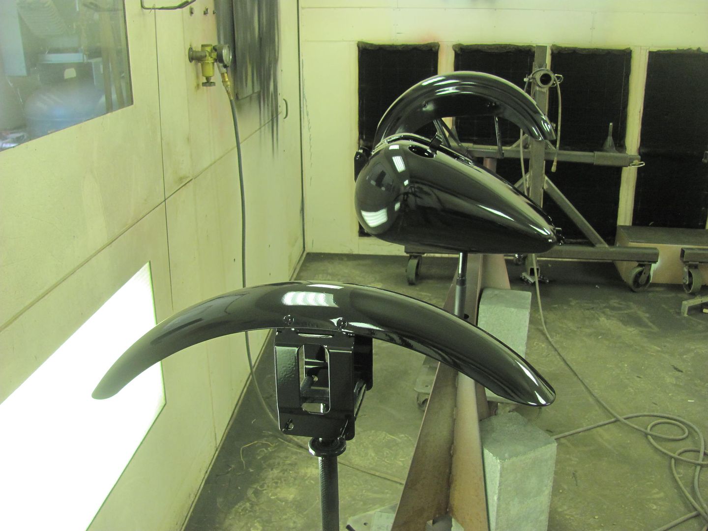
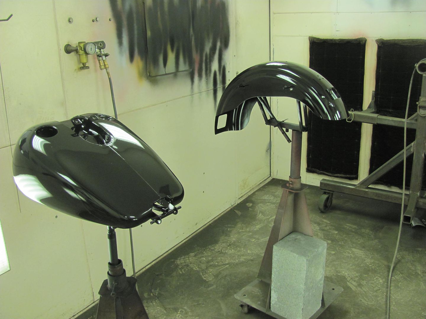
Look Scott, the dent's gone...
More progress on the wagon, got some SPI epoxy sprayed, hopefully this will wet sand out and be ready for BC/CC.
Also got some primer on the sheetmetal for an 01 Dyna
Look Scott, the dent's gone...
Capt Chrysler
Well-known member
Robert,
Please make Kyle wear a dust mask.
Capt. Chrysler
Please make Kyle wear a dust mask.
Capt. Chrysler
Thanks, message delivered...
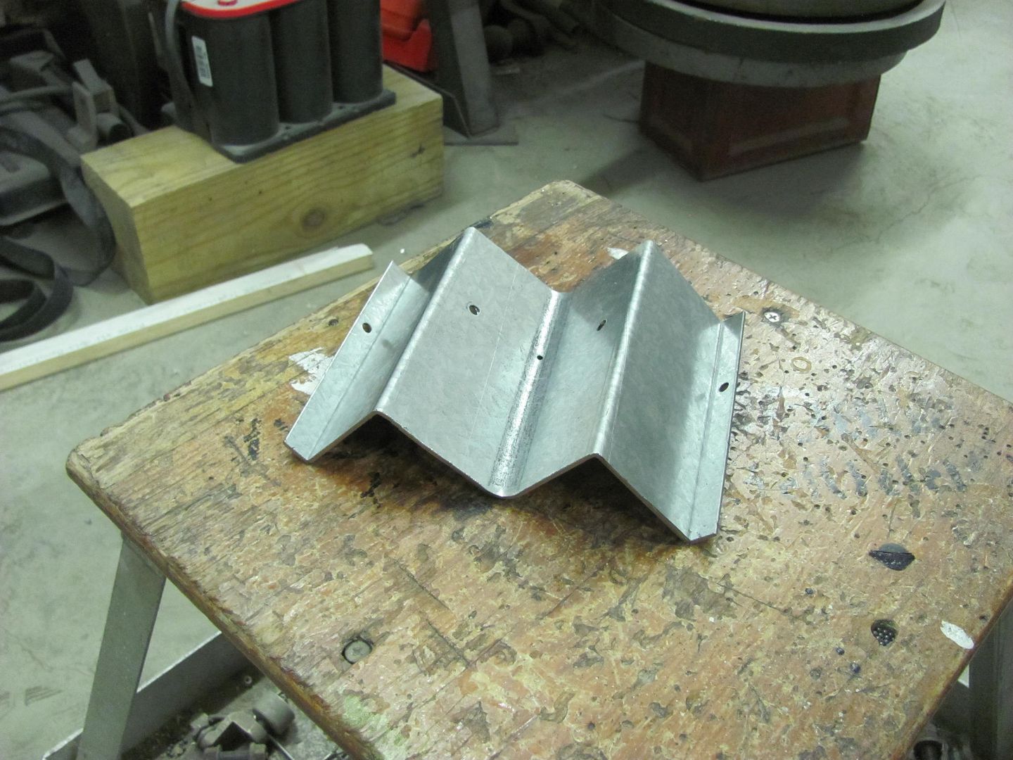
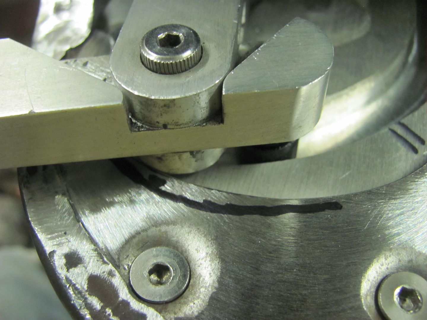
Here's a nifty trick I used in the shop recently, perhaps someone can make use of it on their own projects.. We had some standoff "hat sections" to fabricate a couple weeks back, and needed multiple quantities.
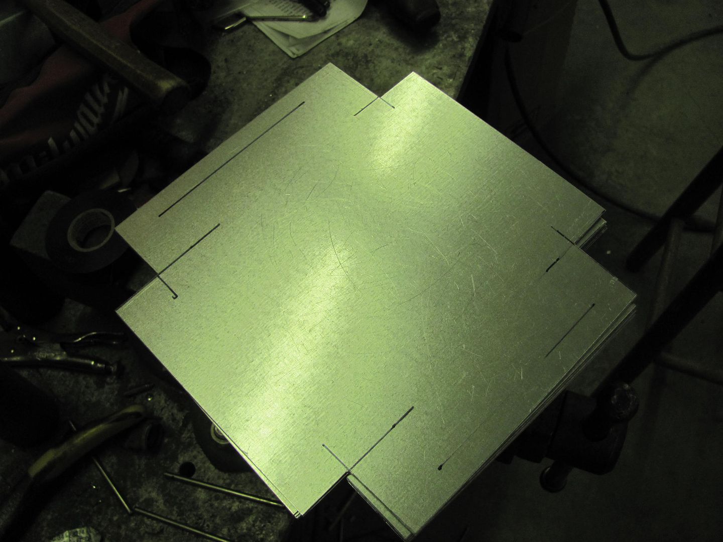
One of the bends was to form a 1/2" flange, so the press brake was used with a 1" wide die...
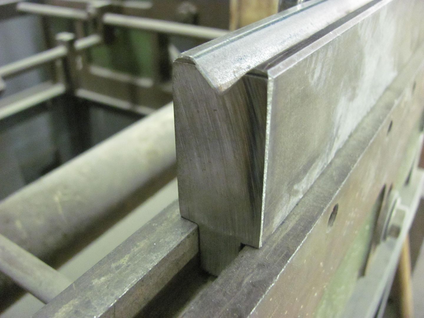
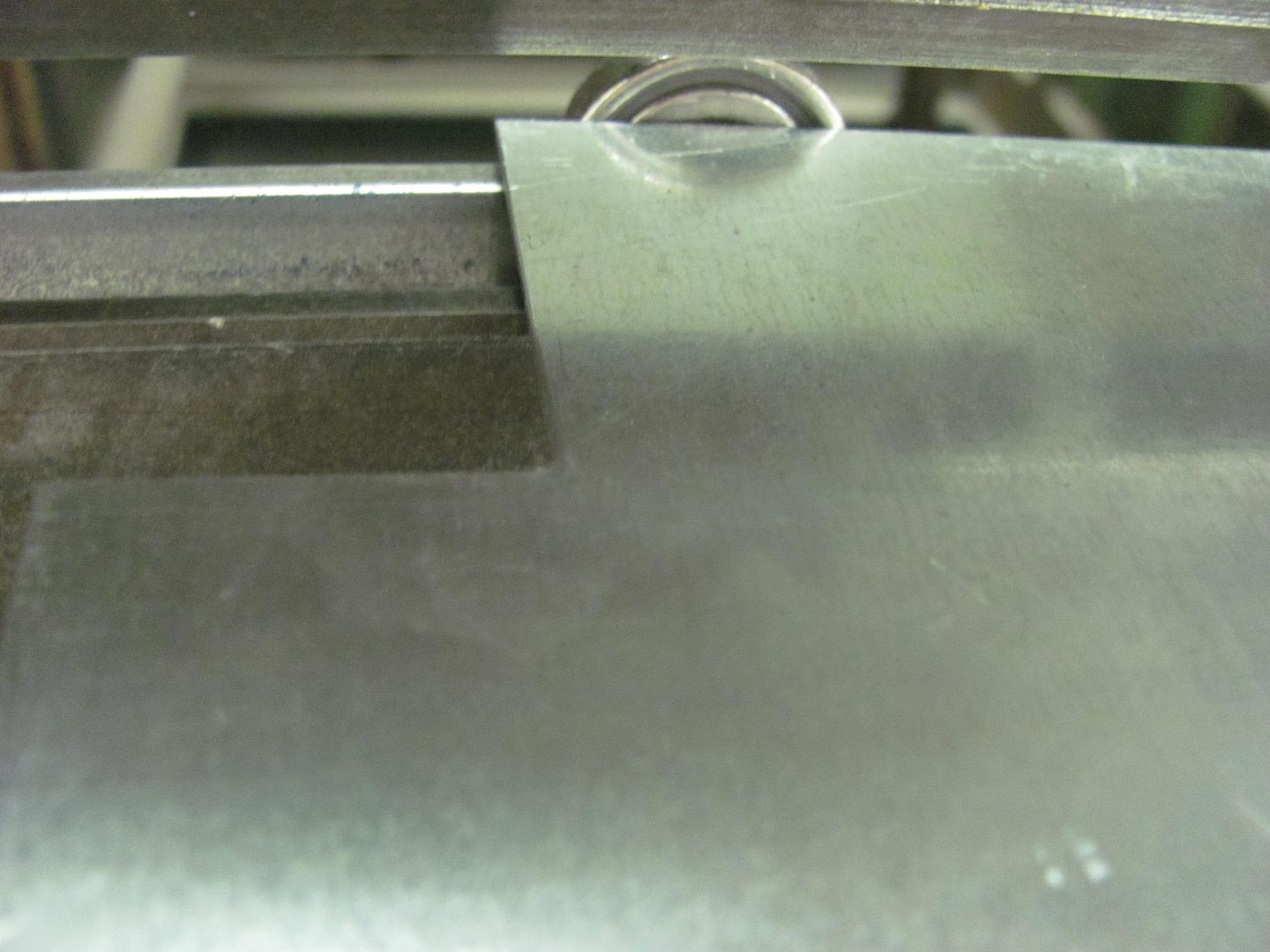
Using some rare earth magnets placed on the back side of the lower die to act as a backstop.... much easier set up than fooling with the Diacro's built in backstop..
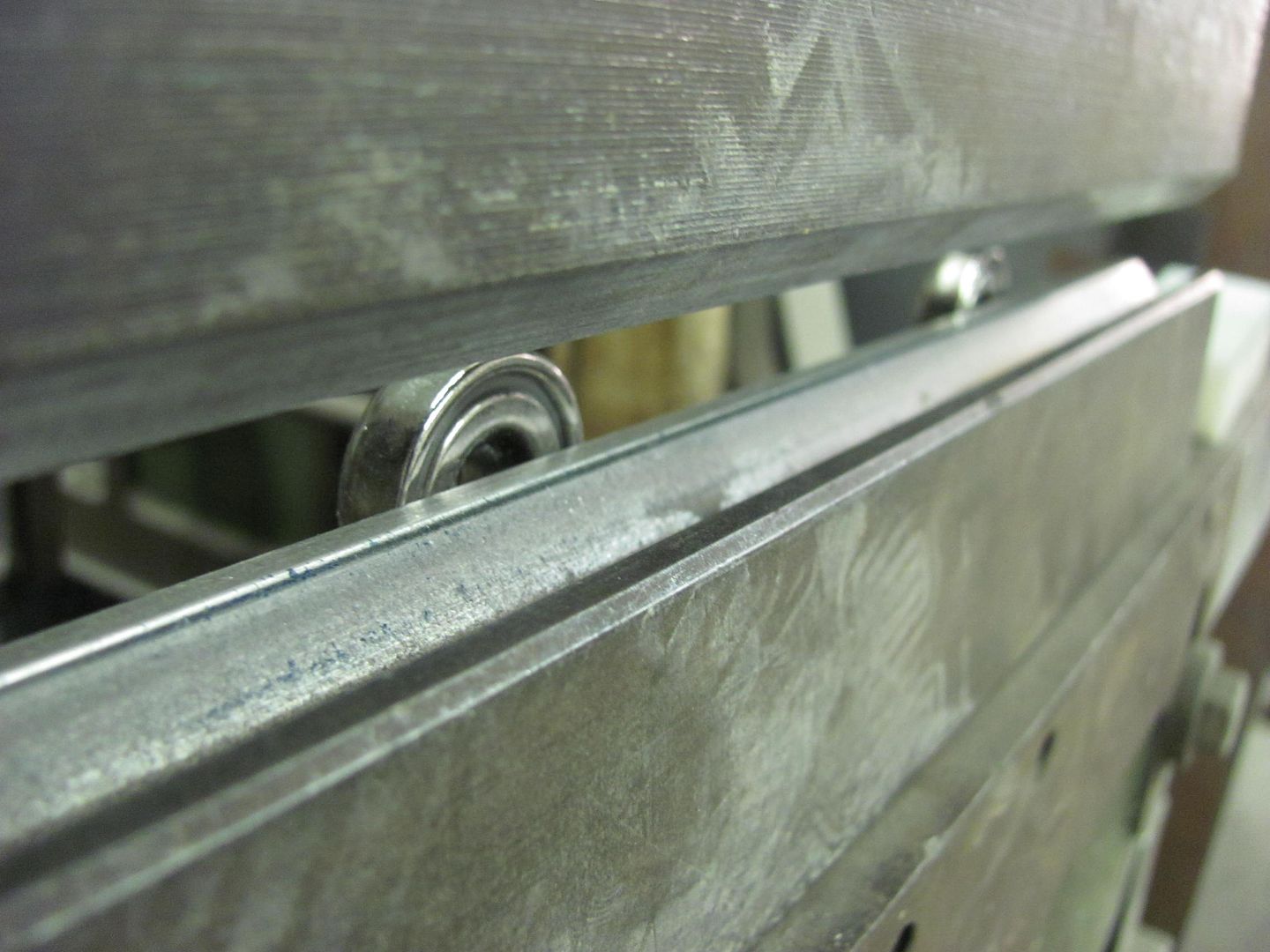
The bonus was it pulled the galvanized sheet metal in tightly toward the magnet, a self-loading if you will...
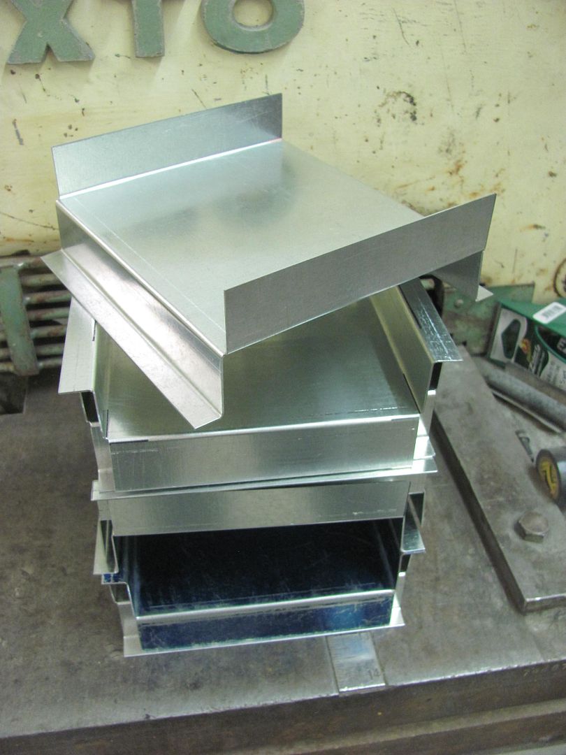
Some of the finished products...
Here's a nifty trick I used in the shop recently, perhaps someone can make use of it on their own projects.. We had some standoff "hat sections" to fabricate a couple weeks back, and needed multiple quantities.
One of the bends was to form a 1/2" flange, so the press brake was used with a 1" wide die...
Using some rare earth magnets placed on the back side of the lower die to act as a backstop.... much easier set up than fooling with the Diacro's built in backstop..
The bonus was it pulled the galvanized sheet metal in tightly toward the magnet, a self-loading if you will...
Some of the finished products...
shortykorte
Well-known member
That's purdy!
Great work!
Great work!
don long
Well-known member
Nothing like a good successful day in the spray booth
Those parts look super, great shine and depth
Those parts look super, great shine and depth
b-body-bob
Well-known member
Hi Robert, I have a question here fitting an AMD quarter panel skin on a 69 road runner.
I've got it cut to fit, and the door gap is right, etc. The problem is, when it's laying against the car, the bottom pinch area is way off the bottom of the rocker. When I hold the quarter up against the bottom of the rocker, it gaps out at the top away from the car.
If I clamp it in place, and it puts a lot of stress into the metal. If I unclamp either the top or the bottom, it pops out forcefully. That seems like a recipe for a warped panel, but as far as I know, that's just the way it goes when replacing a quarter.
So my question is, should I keep with the clamps until I get it where it needs to be and tack it in place ignoring the stress? Or, do I need to figure out some way to bend the bottom of the quarter so it aligns naturally with the rocker and doesn't have to be forced to fit? If it needs to be bent, do you have any tips that might work, other than buying a brake to do it?
Here is a photo, you can see the bottom in front of the rear wheel is hanging way too low because of the incorrect angle.
Attachments

Bob, this may be intentional by the panel's mfr to put some stresses in the panel to force outward and thus give the panel a bit more support. If it seems it will be too much stress, what I would use in my shop is a Go Kart slick on the e-wheel with a radius anvil that matches what should be there as a radius at the bottom. The Go Kart slick allows you to add some roll in that panel area without affecting shape, effectively a slip roll. The e-wheel also would have sufficient throat to accommodate this panel, where a similar set up in a bead roller with a skate board wheel may provide a similar function but doesn't have the same throat capacity that the bottom of the flange area may require.. You could also cut a piece of pipe and lay in the bottom and attempt to roll it around. Less controllable than the slick, but certainly more accommodating to anyone who may not have an e-wheel in the corner..
b-body-bob
Well-known member
Thanks Robert. I'll see if I can shoot a short video of how it pops when unclamped to give an idea how much stress there is.
It looks like the one I've got for the other side has the same condition so you may be right and it is supposed to be that way.
OTOH, if it's wrong it wouldn't be the first flaw I've noticed in an AMD part.
FWIW there's a sharp edge at the bottom, not a roll over which it seems like you were thinking in your reply. (If I'm wrong about that, apologies in advance)
zmotorsports
ALLIANCE MEMBER
Absolutely amazing work as always Robert.
Mike.
Mike.
nonhog
Well-known member
Thanks Robert. I'll see if I can shoot a short video of how it pops when unclamped to give an idea how much stress there is.
Maybe you can add pics (as well as your video) as your progressing with this repair. Adding details of your solution to this would likely be very helpful to wannabe body guys like me. Robert seems pretty gracious so I doubt he would feel like your hi jacking his thread?
b-body-bob
Well-known member
Maybe you can add pics (as well as your video) as your progressing with this repair. Adding details of your solution to this would likely be very helpful to wannabe body guys like me. Robert seems pretty gracious so I doubt he would feel like your hi jacking his thread?
Rather than hijacking Robert's thread, I can point you to this thread on another forum where i've been posting but not getting a lot of advice
which is why I'm here to ask Robert!The Lift Off Hood Playground › A12 Forum › A12 - Project Cars: Jamb job
Along those lines I know there's been plenty of people who have dealt with this same situation but apparently they didn't post what they did.