To avoid these ads, REGISTER NOW!

MP&C Shop Projects

b-body-bob

Well-known member
Joined
Oct 10, 2011
Messages
1,621
Location
Almost Heaven
Bob, I was thinking the bottom was rolled in, so how about a closer picture of the crease? We'll take a look and see what may work for you, give you a couple options..

I found a couple of photos that show it pretty clearly. One shows what it's supposed to look like. At that point I had forced it together with clamps hoping that would bend it enough but knowing good and well that it wouldn't.

The other show how far off it is with the rest of the quarter aligned where it should be.

The bottom of the rocker is horizontal and the pinch weld is at 90* to that.

FWIW the outer wheel tub is out of the car, once I get the quarter fit to the rocker, I'll fit the tub to the quarter. At least that's my forward plan, good or bad.
 

Attachments

  • IMG_1265.jpg
    IMG_1265.jpg
    83.1 KB · Views: 200
  • under_rocker.jpg
    under_rocker.jpg
    52 KB · Views: 205
To avoid these ads, REGISTER NOW!

b-body-bob

Well-known member
Joined
Oct 10, 2011
Messages
1,621
Location
Almost Heaven
I do not have one, and as far as I know, nobody I know does either.

I considered trying something like a B&D workmate clamp table, getting a couple people to help with handling the quarter, someone else to stand on the table so it's stable, then clamping right along that crease line and carefully folding it further over. After looking closer I don't think it will t work because of the lip around the wheel opening prevents me from clamping it in the center of the table, and the sides of it aren't deep enough to where i can get it in there at the very edge of the table.
 

iajonesy

Well-known member
Joined
Feb 8, 2009
Messages
2,467
Location
Iowa
Hi guys. I'm no expert but I have seen some 1/4's done before and some of them had more spring back than Bob's and they came out good after mounting them solid. I do agree that a little extra bend would help with the mounting job, though. Just my 2 cents.

Robert, I know you really like the SPI product line but would like to know if it's rookie friendly? Thanks.

Mike
 

b-body-bob

Well-known member
Joined
Oct 10, 2011
Messages
1,621
Location
Almost Heaven
Thanks for the info Mike. I've got no experience with it, so the need to bend the thing or force it in place took me by surprise.
 

Bob Heine

ALLIANCE MEMBER
Joined
Oct 24, 2009
Messages
10,703
Location
Boca Raton, Florida
Robert, I know you really like the SPI product line but would like to know if it's rookie friendly? Thanks.

Mike
Mike, since Robert is so far from rookie status, I'll put in my two rookie cents. SPI black epoxy was only the second two-part paint I'd ever used. I'm one of those people who has trouble mixing paint/activator/reducer 4:3:1.5 or whatever so SPI Epoxy is perfect for me. You mix one part SPI Epoxy with one part activator. You also mix the Universal Clear one to one with it's activator. If you have a problem, call the Tech hotline and you get help from Barry, the owner and founder of SPI. I haven't called outside regular business hours but Barry answers or returns your call within minutes even on holiday weekends. If you can't get it to spray the way you want, he'll walk you through gun setup while you are on the phone. If nobody near you sells SPI, they (2-day) ship their products to your door for free.
 

iajonesy

Well-known member
Joined
Feb 8, 2009
Messages
2,467
Location
Iowa
Thanks for that info Bob Heine. I've heard Robert rave about SPI products for a long time and I've seen the results of his paint jobs and they are beautiful, but wondered how touchy they were. The fact that you mix them one to one makes it easy for me, too. Thanks for your reply. Just one more reason to love this site.

Mike
 
OP
M

MP&C

Well-known member
Joined
Oct 21, 2009
Messages
4,396
Location
Leonardtown, MD
Bob, thanks for picking up the slack for me, was busy in the booth again.. :lol:


Mike, I always had good luck with the House of Kolor epoxy, and am finding this to sand better with little to no loading, less expensive, easy to spray, and as Bob indicated, awesome customer service in case their online data isn't sufficient.


Well, we had gotten some more sanding done......


Picture%202928.jpg


Picture%202929.jpg


Picture%202930.jpg


.....and since it was still early in the evening, mixed up some more epoxy....


Picture%202931.jpg


Picture%202932.jpg


Picture%202933.jpg


Picture%202934.jpg
 
OP
M

MP&C

Well-known member
Joined
Oct 21, 2009
Messages
4,396
Location
Leonardtown, MD
I do not have one, and as far as I know, nobody I know does either.

I considered trying something like a B&D workmate clamp table, getting a couple people to help with handling the quarter, someone else to stand on the table so it's stable, then clamping right along that crease line and carefully folding it further over. After looking closer I don't think it will t work because of the lip around the wheel opening prevents me from clamping it in the center of the table, and the sides of it aren't deep enough to where i can get it in there at the very edge of the table.


Bob, my initial suggestion was going to be using a bead roller with a tipping wheel and flat skateboard wheel at the bottom. This shows the results....


Picture%202712.jpg


For the lower flange that looks like it could use a more defined angle, I've used the same tipping wheel with a skateboard wheel that has a VEE relief cut into it. It did these in making a Task Force Chevy p/u upper windshield panel....


Picture097.jpg


Since you don't have that option, I'd suggest making a shot bag or sand bag, if you don't have one. An old leather purse from a yard sale for a couple bucks filled with sand that lays fairly flat would be a good support for the lower crease (not referring to the flange here) and then use this tool and hammer.....


Picture659.jpg


....to tap along the entire length of the crease to make it bend a bit more. The sand bag would support the areas adjacent to the crease while the chisel tool pushes the crease into the sand bag. I would say to use light taps at first, see how it reacts, and judge where to go from there.
 

b-body-bob

Well-known member
Joined
Oct 10, 2011
Messages
1,621
Location
Almost Heaven
Thanks Robert, I'll see what I can do

I messed with it more last night, with no progress. I'm not sure I've got the experience to get it fitted right, but on the other hand I've got plenty of time.
 

b-body-bob

Well-known member
Joined
Oct 10, 2011
Messages
1,621
Location
Almost Heaven
OK I messed with it a bit more and took some photos. If this is normal and I should just press on let me know but the amount of stress in the panel sure seems high to me.

First, here are photos showing how it gaps out with the bottom clamped to the rocker as it should be (or at least close). It's like a spring at this point.

Photos 1 and 2 show it is flat against the door and wheel ends. Photos 3 and 4 show how far it is off the car at top, front and back. It also forces the panel up but the photos intended to show that, didn't.
 

Attachments

  • IMG_1274.jpg
    IMG_1274.jpg
    119.4 KB · Views: 164
  • IMG_1272.jpg
    IMG_1272.jpg
    128 KB · Views: 167
  • IMG_1281.jpg
    IMG_1281.jpg
    111.1 KB · Views: 1,108
  • IMG_1276.jpg
    IMG_1276.jpg
    113.9 KB · Views: 160
Last edited:

b-body-bob

Well-known member
Joined
Oct 10, 2011
Messages
1,621
Location
Almost Heaven
Now, here are photos showing how it lays flat against the car like it's supposed to. There are 3 clecos holding the whole quarter on at this point, and if I took the off, the panel would still lay flat against the car. There is no stress in the panel at all at this point. The gadget I cobbed up to hold it is in place but the weight of the panel is on the clecos.
 

Attachments

  • IMG_1285.jpg
    IMG_1285.jpg
    108.8 KB · Views: 141
  • IMG_1282.jpg
    IMG_1282.jpg
    117.8 KB · Views: 134
  • IMG_1283.jpg
    IMG_1283.jpg
    111.5 KB · Views: 128
  • IMG_1288.jpg
    IMG_1288.jpg
    121.1 KB · Views: 127

b-body-bob

Well-known member
Joined
Oct 10, 2011
Messages
1,621
Location
Almost Heaven
I showed those photos to my wife, and she said we'd go out there early tomorrow and bend it. I reminded her that the panel cost $400 but she didn't back down. :D

I figure the end of this is going to be me rigging something up with angle iron, all thread, and bubble gum, and popping a dent in the panel wrestling with it. At least it will be interesting.
 
OP
M

MP&C

Well-known member
Joined
Oct 21, 2009
Messages
4,396
Location
Leonardtown, MD
Bob, looking at this picture...


attachment.php


The bottom area that should be parallel to the ground is actually pulling down just before you get to the flange crease. I think this is also contributing to the issue, and I would try and resolve this a bit before attacking the crease outside that area. I would try a nice smooth 2x4 or 2x6 as a base, set the flat area on top with the flange pulled snug against the side, and tap it with a dead blow or rubber mallet to see if you can make the flat area actually flat.. This should help some of the issue.

Does that make sense? If not I can do a pictorial....
 

b-body-bob

Well-known member
Joined
Oct 10, 2011
Messages
1,621
Location
Almost Heaven
Yes I knew I'd have to wail on that eventually so it's tight for welding. I thought once I had the major part of it parallel to the rocker that last bit in the corner would have to be hammered up and against the pinch before welding it.

I'll flatten that out tomorrow and see if it helps, thanks
 

b-body-bob

Well-known member
Joined
Oct 10, 2011
Messages
1,621
Location
Almost Heaven
Robert, I got a tip from another board from a couple of different people who had similar problems. They recommend cutting the panel underneath, because just past the end of the rocker the quarter is formed to fit around the inner wheel well. All those curves and bends aren't going anywhere, so that transfers the stress from trying to force it into place up into the "floppy" part of the quarter.

At least it makes sense to me anyway.

Here's a photo showing what I'm talking about. I will probably cut a slot just past where the bottom part ends so the bottom can move without influencing the wheel well opening and rest of the panel. Once the panel is fit and welded in, I'll go back and patch the slot up and nobody will ever know unless they read this thread. ;)
 

Attachments

  • IMG_1278.jpg
    IMG_1278.jpg
    117.5 KB · Views: 152
OP
M

MP&C

Well-known member
Joined
Oct 21, 2009
Messages
4,396
Location
Leonardtown, MD
My thoughts are that more welds = more heat = more distortion.. If you need it, by all means do it. If it can be done without it, you will be ahead of the game later when it comes to straightening out the panel..
 

b-body-bob

Well-known member
Joined
Oct 10, 2011
Messages
1,621
Location
Almost Heaven
Understood. There's no metal working anything down there either, it's layers of metal.

In this case it'll only be an inch or two at most, underneath the rocker, and the same curves and angles holding it off now will also serve to prevent any warpage. That's my forward plan anyway. :thumbup: Also, and I just thought of this, when I get to the point of fixing the slot, the quarter will be welded to the rocker and to the wheel well, so more stabilization.

If those thoughts are off-base, let me know, but it's all based on things I've learned from your threads :bowdown:

FWIW I was talking to my wife about it more on about how I could use a workmate to bend it straight, if the panel would fit and if not for that doggone end with the wheel well on it ... and the light bulb came on.

I hadn't checked it out yet but came in this AM to replies on the other board (http://www.forbbodiesonly.com/moparforum/forum.php) advising me on the problem.
 
OP
M

MP&C

Well-known member
Joined
Oct 21, 2009
Messages
4,396
Location
Leonardtown, MD
The bottom area of the quarter that will be up against the bottom of the rocker is not the same profile as the rocker. The rocker is flat, and parallel to the ground. The quarter is not, it takes a nose dive and needs to be flat. My only concern with the cut and weld advice is that they may not have known how this is easily fixed without welding, but with a cut off wheel and welder, likely what they had available, it was easily fixed for them. This falls into the same category as welding up pie cuts.... there are other ways to accomplish the same thing more correctly. No disrespect to their methods, but adding any additional weld in that area burns off any paint finish it may have (unnecessarily) where it is now prone to the same rust effects that cause you to be there now replacing sheet metal. The method I suggest would keep paint finish intact, minimize panel distortion, and should give you a better end result. I would attempt to flatten that area first before cutting anything, and check fitment again afterward.
 

b-body-bob

Well-known member
Joined
Oct 10, 2011
Messages
1,621
Location
Almost Heaven
Yes I still plan to flatten the whole thing out.

Also if you look at the photos again you will see the nose dive starts way back from that bent place it actually starts at the bottom body line stamped into the part. I'm pretty sure the bent place there at the end of the rocker is a result of me forcing it into place with clamps. Chances are I got it too close to the pinch so that part couldn't move with the clamp resulting in that bend.

Anyway, I'm pretty sure that whatever I end up doing in the end will be a better solution than forcing it in place and relying on the welds to hold it there and trusting the panel will cooperate without twisting.

If/when I make any progress I'll report back.

Thanks,
 
To avoid these ads, REGISTER NOW!
OP
M

MP&C

Well-known member
Joined
Oct 21, 2009
Messages
4,396
Location
Leonardtown, MD
Not much to see, still sanding away....


Picture%202936.jpg


Picture%202937.jpg


Picture%202976.jpg


Picture%202938.jpg


Picture%202945.jpg


Picture%202946.jpg


Got about half done with the tail gate and remembered we needed some holes drilled in the new skin for the emblem. Only issue was that I had done some spring cleaning earlier this year and the original skin with the hole pattern and location was now gone. So I sent an email to Mikey at The Stainless Shoppe, as he had an original, and he got me squared away... Thanks Mikey!


Picture%202953.jpg


Picture%202952.jpg


I located the hole for the center alignment pin first, and planned on using some spotters for the remaining 4 holes... Some measurements were taken to insure the emblem was on straight, and then some "backstops" used. The spotters come in a set of various sizes, and typically you never find the exact size you need...


Picture%202957.jpg


Looks like these were made by some of Kevin's buddies...


Picture%202959.jpg


These will go in some 10-24 threaded holes on the emblem. The closest size was the 1/8" spotters, so we'll need to adjust the fit..


Picture%202958.jpg


A couple wraps of fineline tape and we now have a snug fit so the spotters don't fall out..


Picture%202961.jpg


Picture%202962.jpg


Picture%202960.jpg


Then the emblem is located on the tail gate with the center alignment pin, then the back stops. The emblem is pressed onto the tail gate, and the spotters leave their mark on the epoxy paint finish..


Picture%202963.jpg


Next, the studs are installed finger tight using sleeve retainer. This will hopefully keep them from spinning inward any further risking possible damage to the chrome bezel...


Picture%202965.jpg


Picture%202966.jpg


The nuts that come with the emblem are the split thread variety, and I had some threaded ones left over from the Fairlane build, that also are slightly larger in diameter, which may help out as the emblem also serves as a lift handle..


Picture%202967.jpg


Holes drilled and emblem fitted


Picture%202969.jpg
 
Last edited:

Divcod

Well-known member
Joined
Jan 9, 2015
Messages
319
Location
Pacific Northwest
Robert,

May have missed this but do you apply filler directly to metal vs sandwiching it between epoxy? I have a MGA which was restored 20+years ago and it was skim coated to bare metal. Now metal is oxidizing and popping the filler off. I bought the car 2012 and fixed mechanically and just drive as is.

Just ordered SPI epoxy and like to know the gun you use.

Thks
 
OP
M

MP&C

Well-known member
Joined
Oct 21, 2009
Messages
4,396
Location
Leonardtown, MD
SPI recommends spraying epoxy on all the bare metal and using any filler products on top of that. You'll have folks that have been using fillers for decades argue the point that filler sticks better to bare metal, but then an example like yours makes the point as to why not to do it that way. I think part of the issue is the humidity of your location, the other is the chemical reaction of the filler curing generates quite a bit of heat. Put that on a cool body panel and you get condensation that generates between, compromising the adhesion as you have experienced. In some locations that have high humidity issues, the panel can be pre-heated to help prevent the condensation from forming, or use multiple thin layers of filler product to limit the heat generation.


Here's the technical data sheet on the SPI epoxy:


http://media.wix.com/ugd/8ced3e_1e5c47ba23dd43a7a35310ee9f969705.pdf


As shown, they recommend a 1.4 to 1.5 tip for spraying un-reduced epoxy, and a 1.3 to 1.4 for spraying the reduced version as a sealer. I am using Sata guns, I have an RP with 1.3 tip....


Picture%202442.jpg


.....and a 1.7 tipped gun (on left) for epoxy (bought this when I was spraying H/K), a 2.5 tipped gun (on right) for polyester (Slick Sand)


Picture%202440.jpg


Here's the big gaping hole on a 2.5....


Picture%202441.jpg
 
OP
M

MP&C

Well-known member
Joined
Oct 21, 2009
Messages
4,396
Location
Leonardtown, MD
Scott came by this evening after getting the motorcycle back together... The owner had decided to leave off the decals, so it's all black and metallic...


Picture%202977.jpg


Picture%202978.jpg
 
OP
M

MP&C

Well-known member
Joined
Oct 21, 2009
Messages
4,396
Location
Leonardtown, MD
Thanks, we try. Sometimes it takes more than one attempt.. :willy_nil


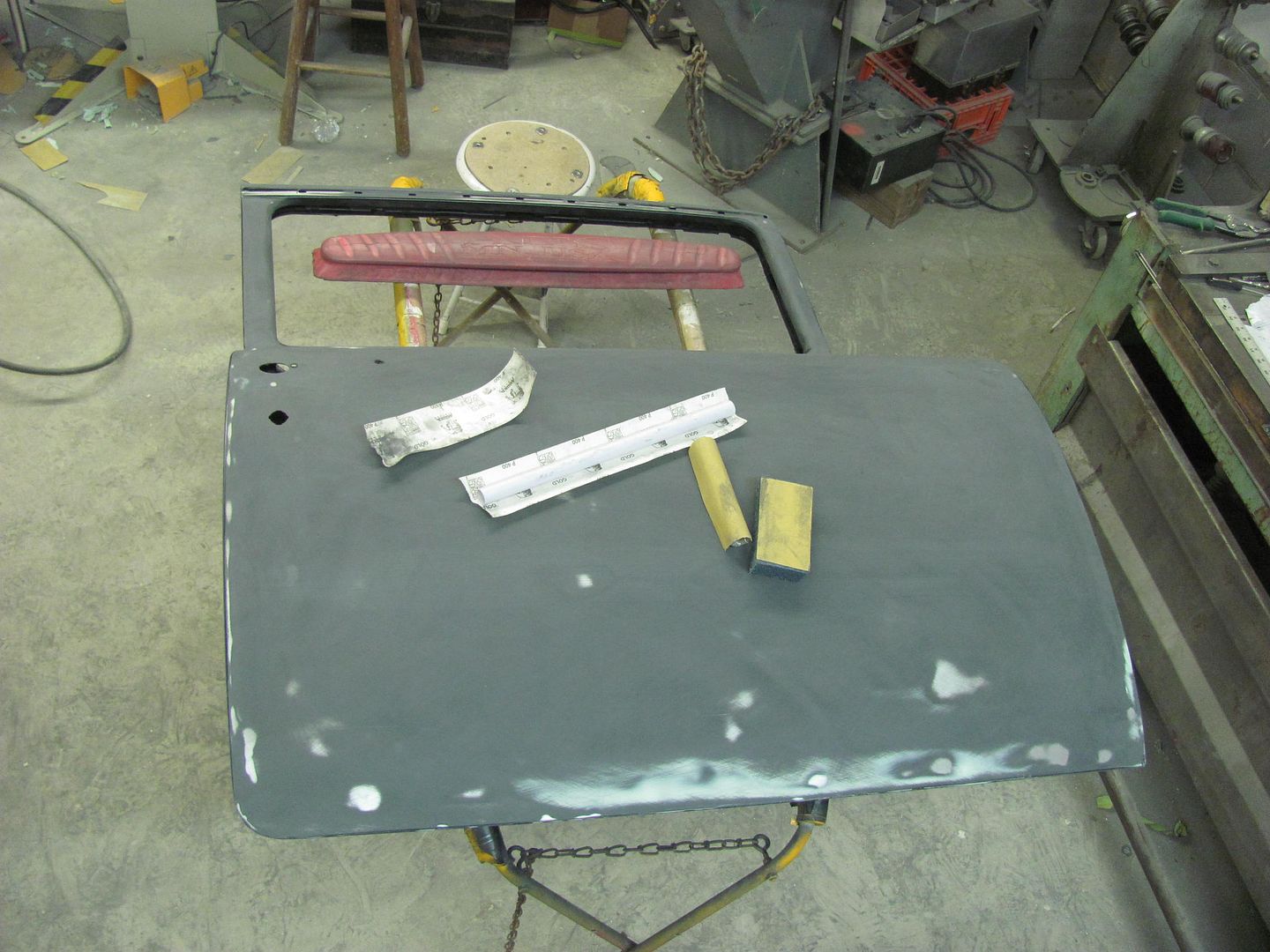
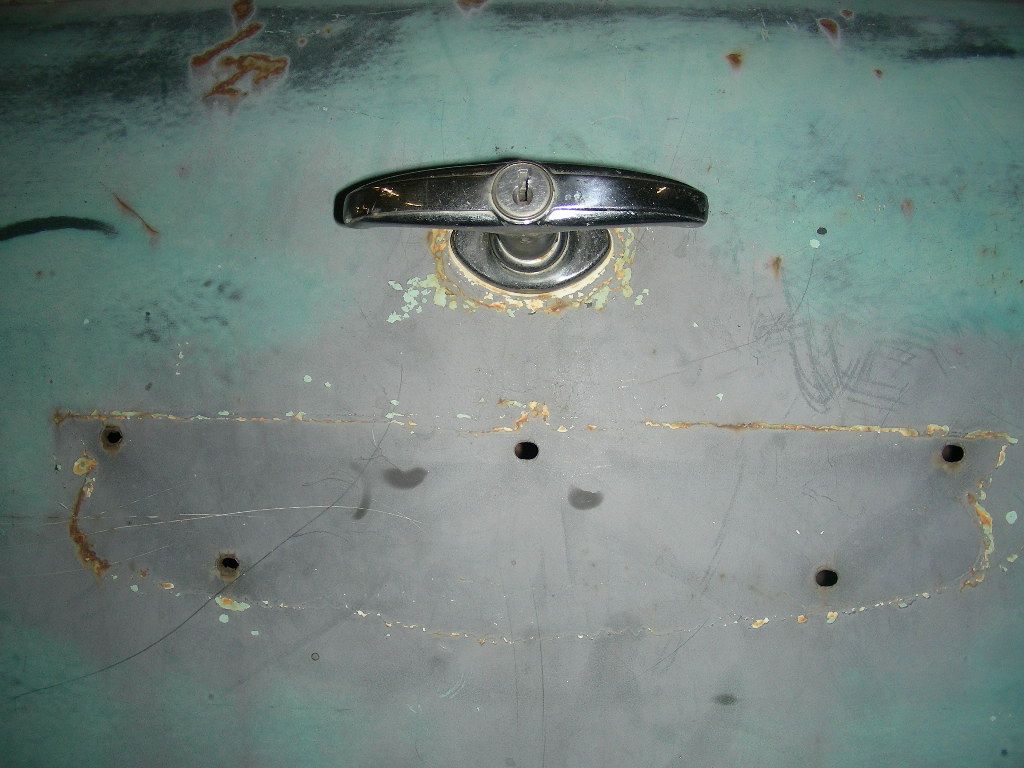
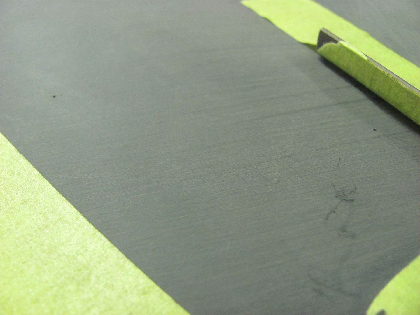
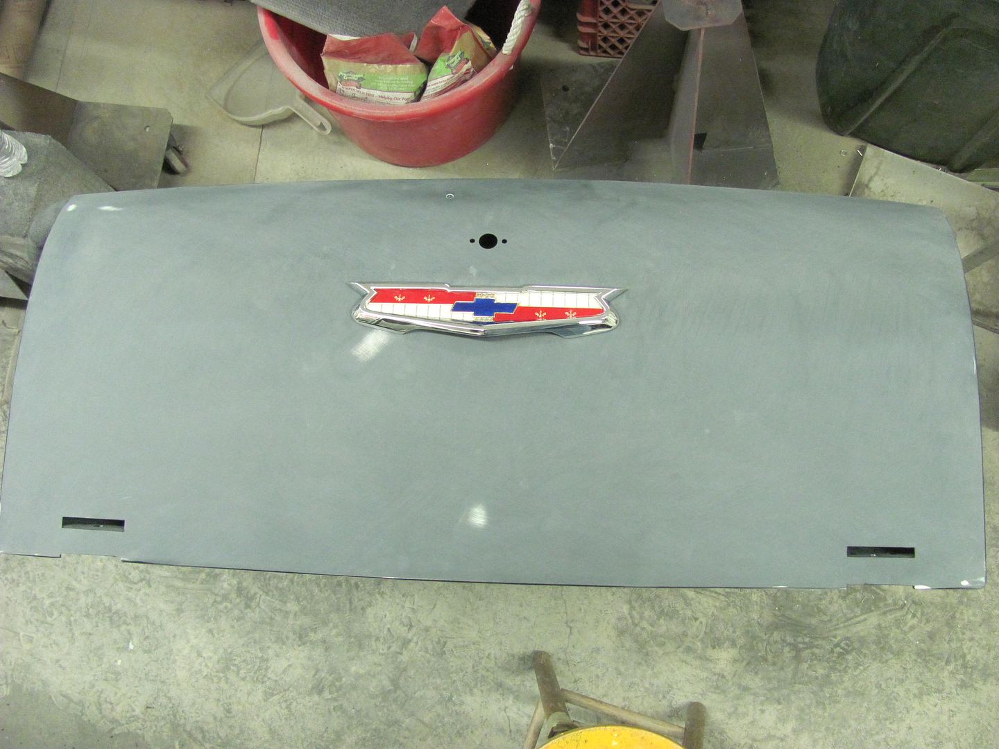
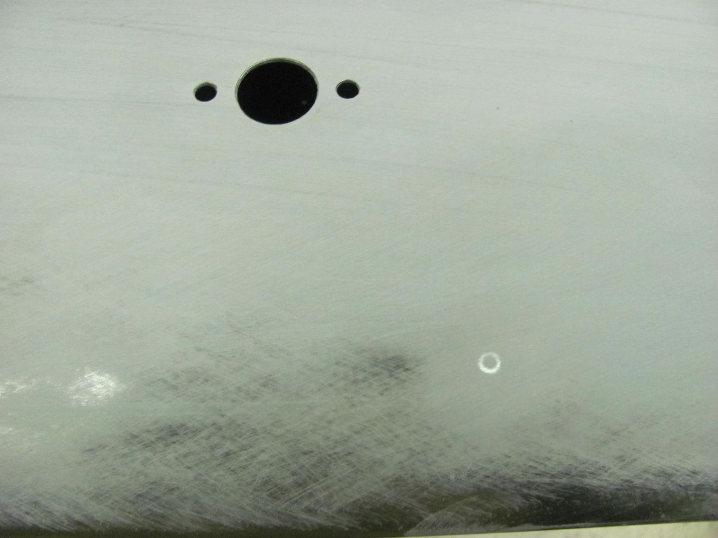
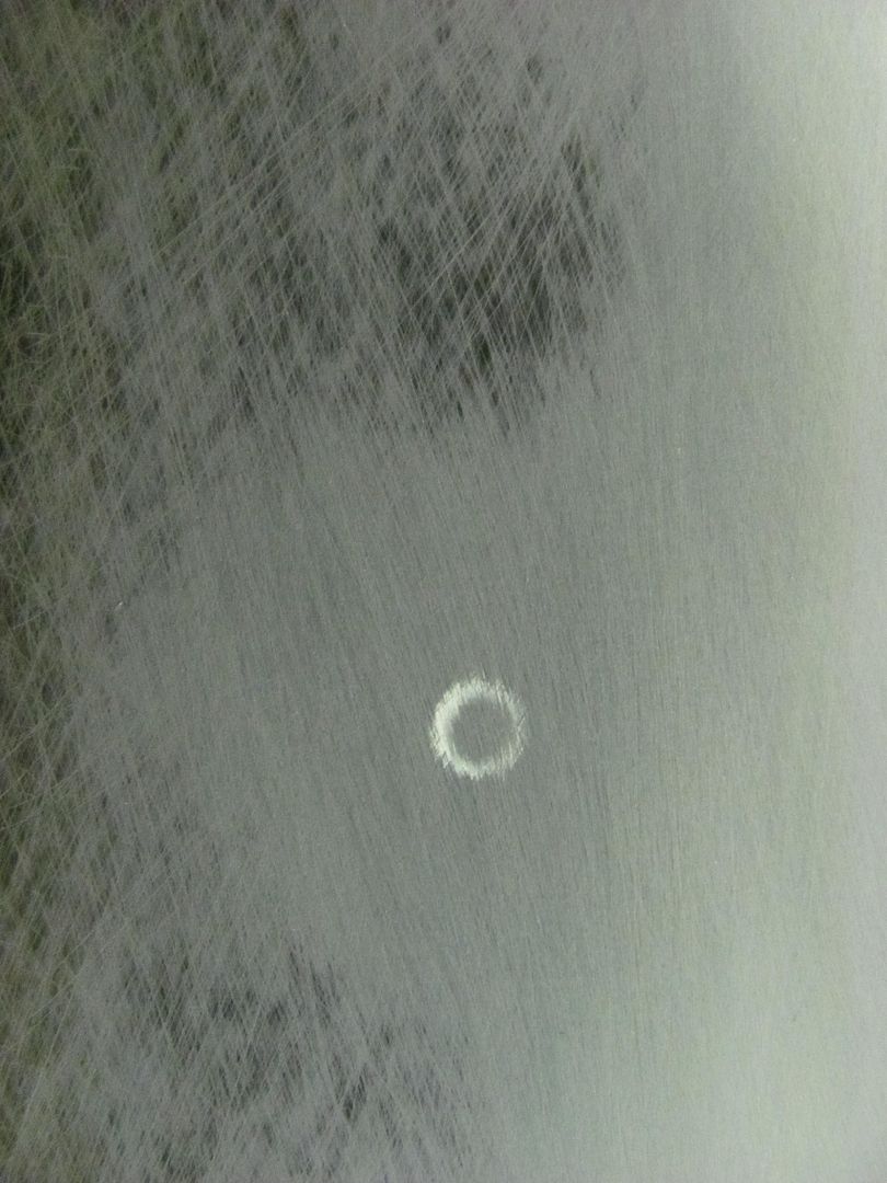
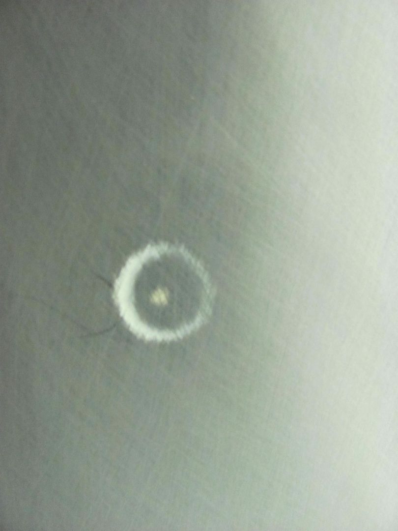
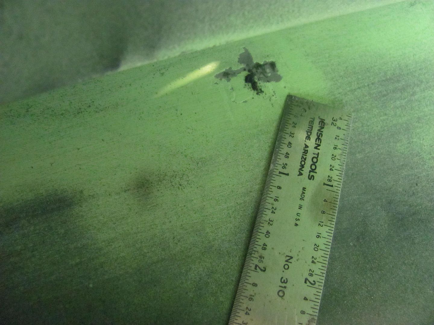
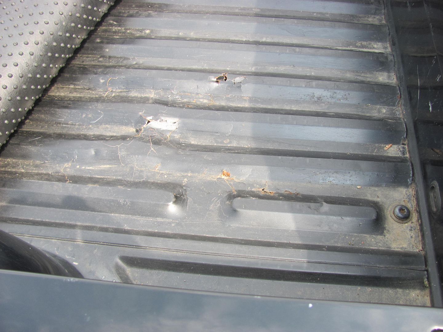
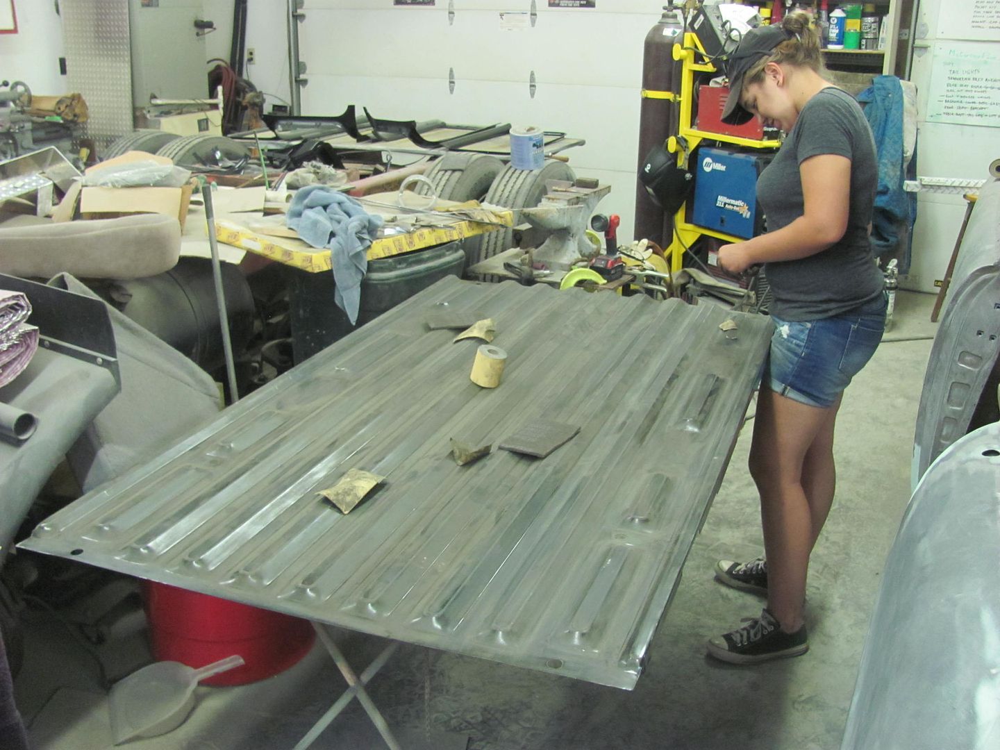
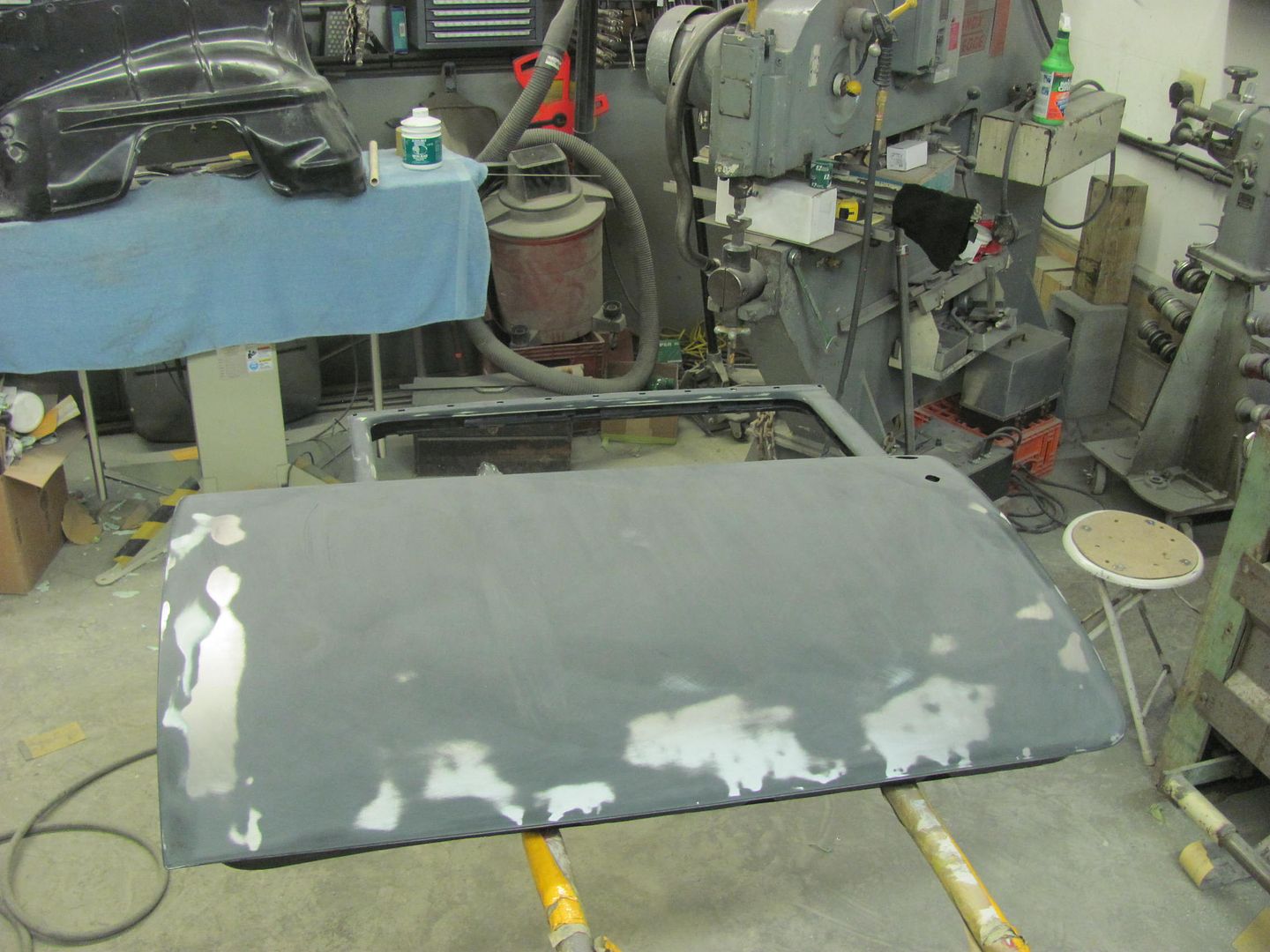
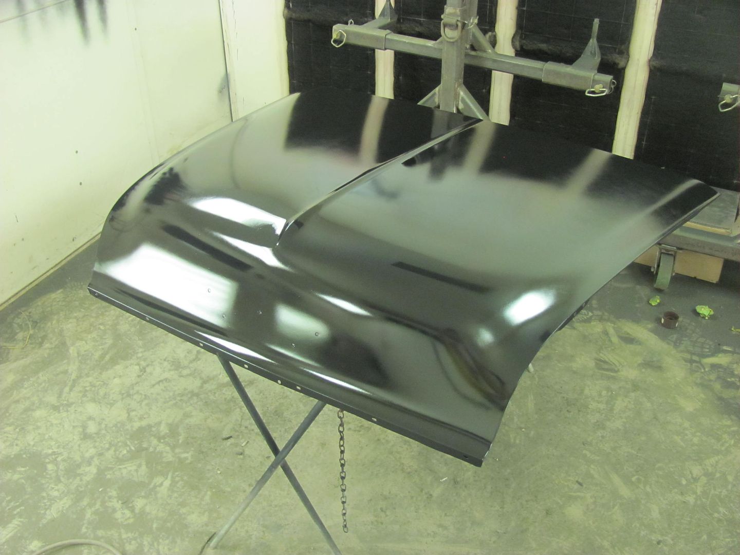
I was blocking out the tailgate the other day and had a "halo" effect appear in the epoxy, shown below just to the right of the latch hole. This has a light skim of Evercoat 416 beneath the epoxy in that area. It was nice and flat while in bare metal, after spraying epoxy, after blocking the Evercoat/ before spraying the last coat of epoxy. I was baffled at what would cause such a nicely formed circle in the paint...


Picture%202939.jpg


Picture%202940.jpg


Picture%202942.jpg


Picture%202944.jpg


Even scratched the area to see if there was any softness to the Evercoat, but no..

Picture%202947.jpg


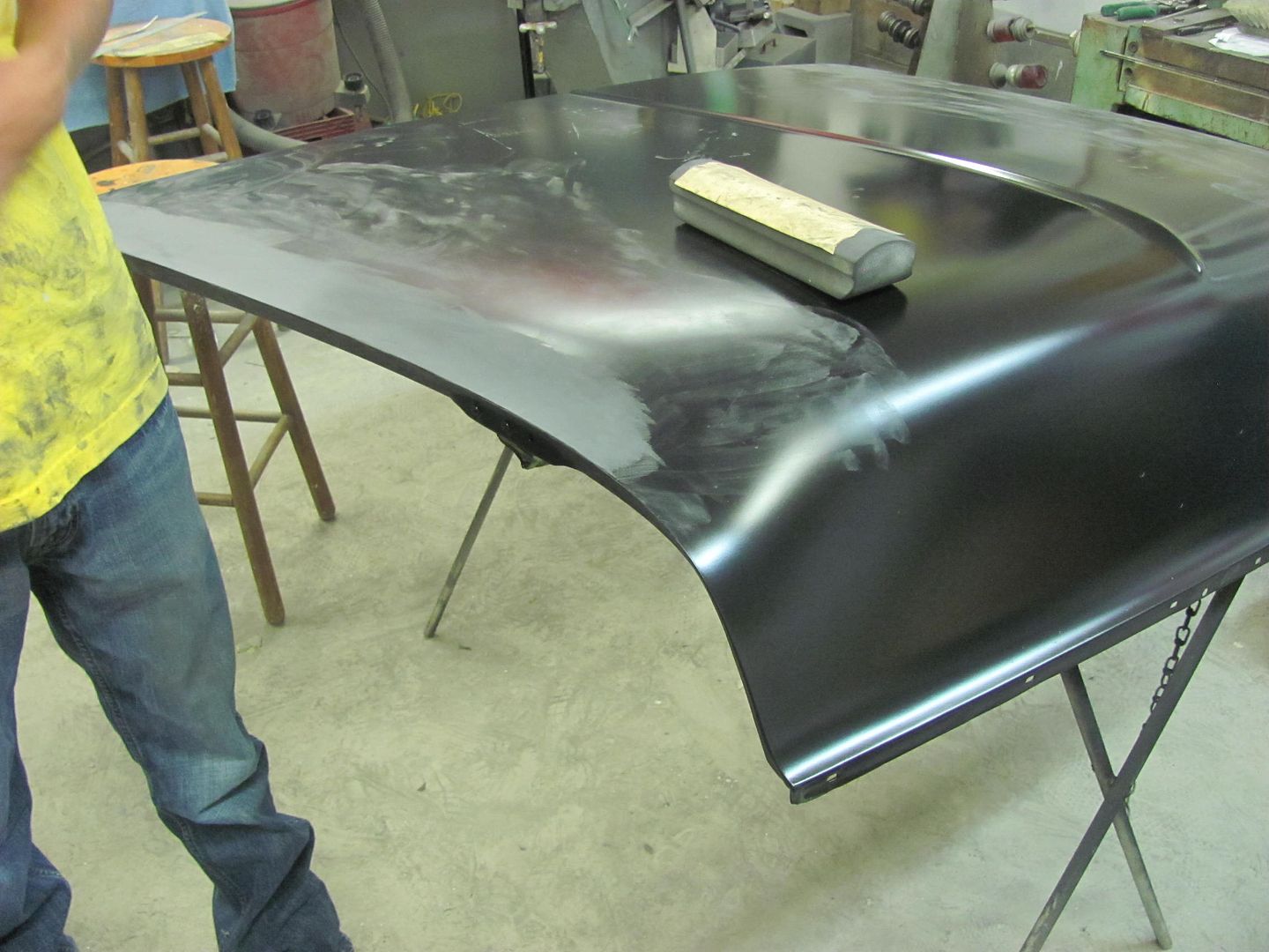
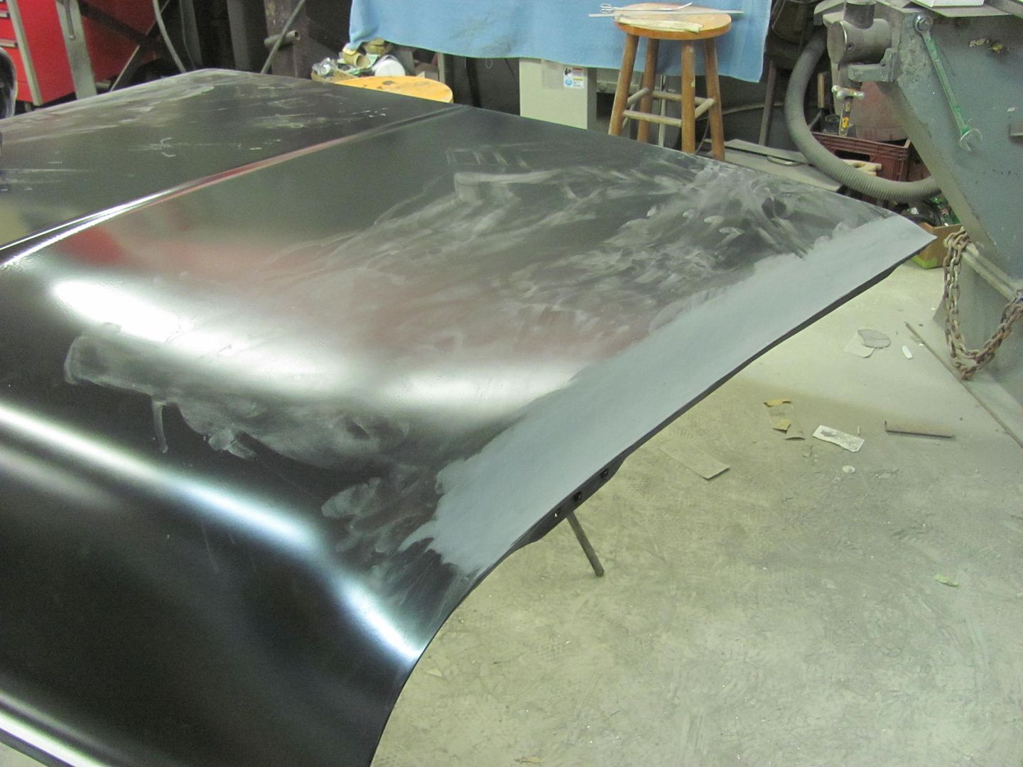
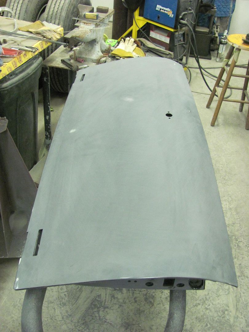
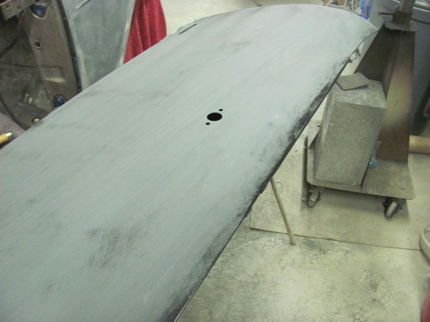
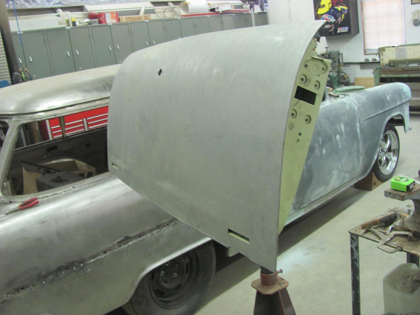
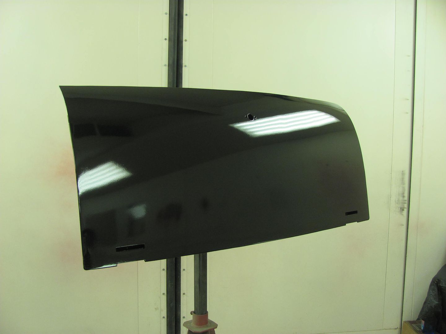
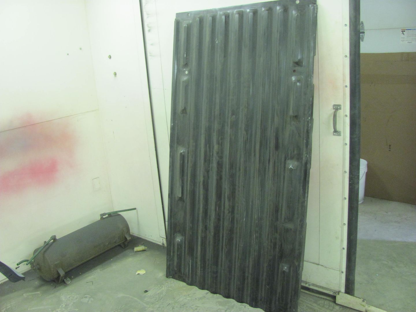
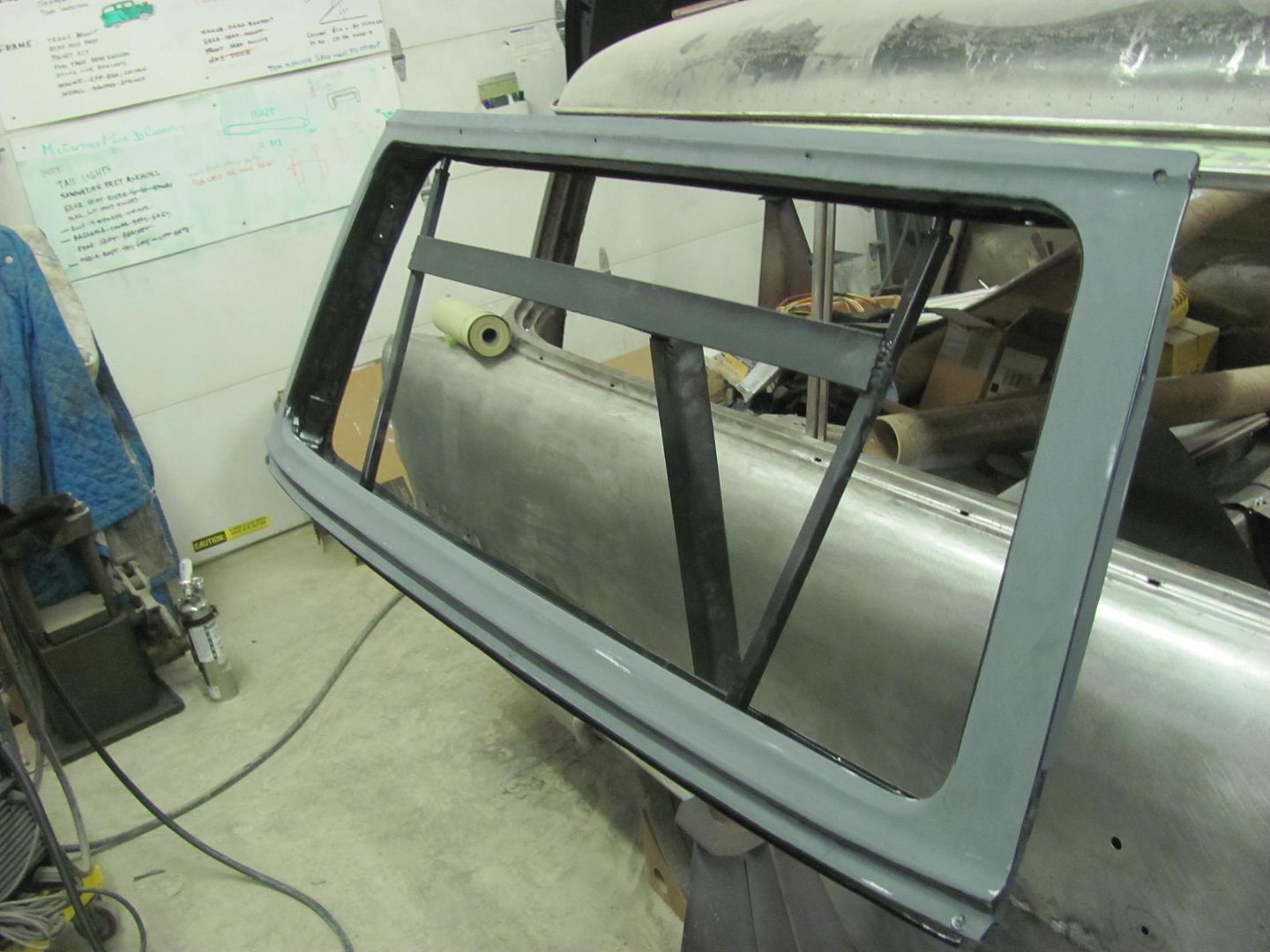
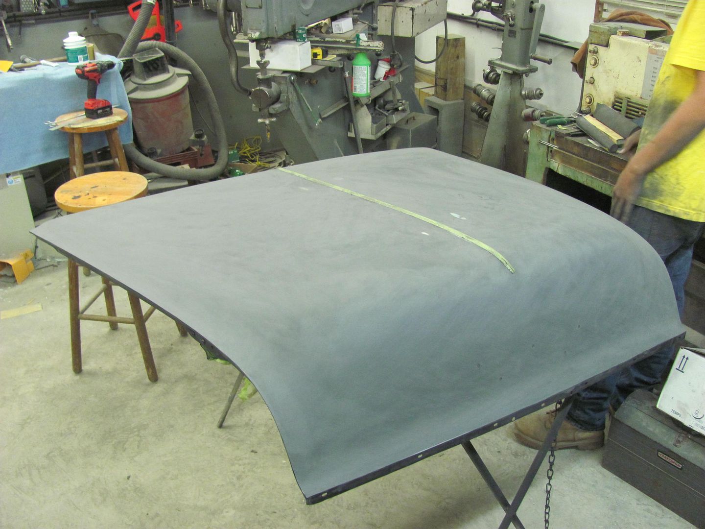
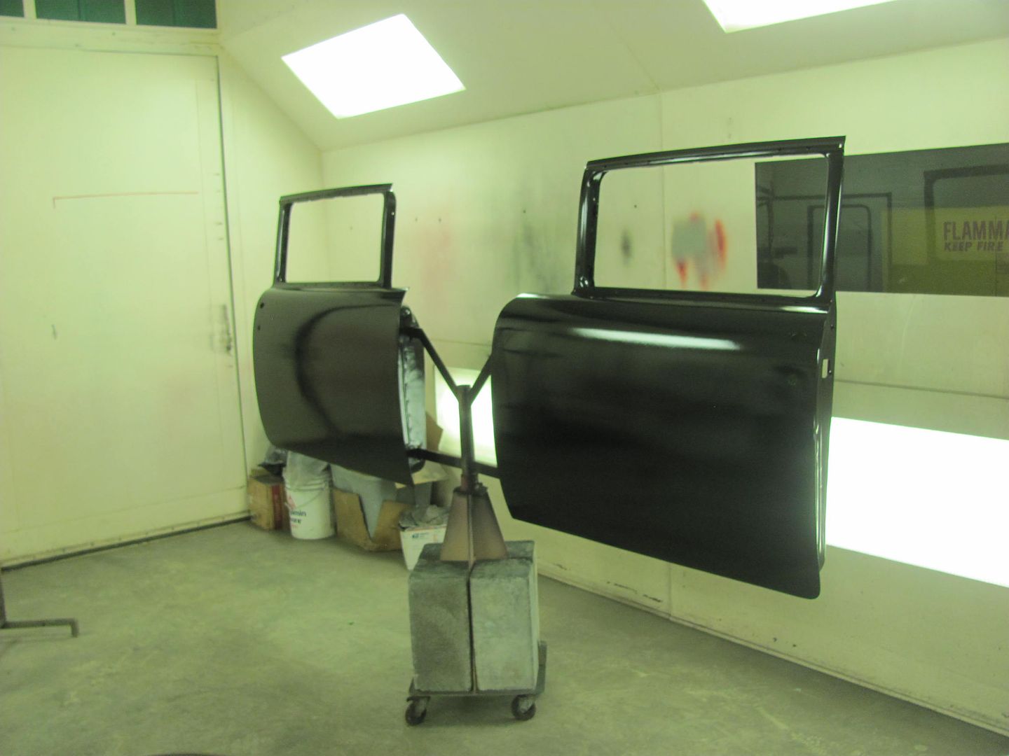
Here's the panel in bare steel before paint and after first coat of epoxy...


Picture%202350.jpg


Picture%202366.jpg


No dings, or defects otherwise seen. I had posted a query on the SPI forum to see if anyone had ever run into this. I don't know why I didn't think of this first, but it was suggested to: 1) look inside 2) only time this type of defect had been seen was dropping screwdriver inside door and left similar mark on outside of door bottom after sanding.


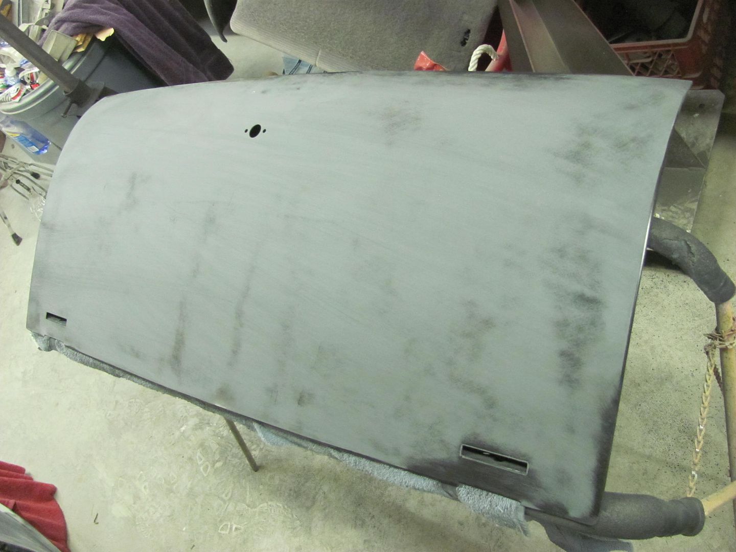
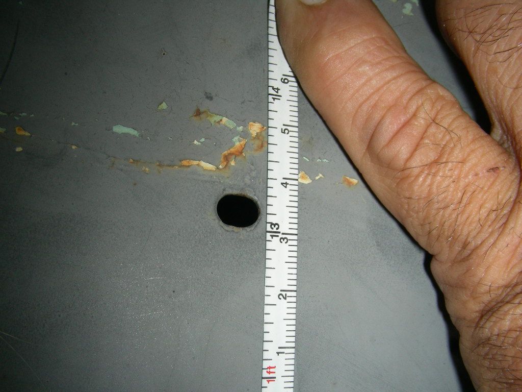
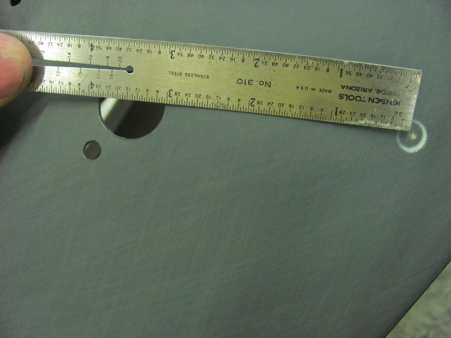
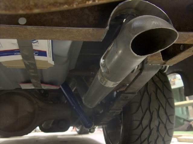
So in full investigative mode, I first measured the distance of the defect from the turn latch hole..


The Halo is approx. 3" away from the handle hole..


Picture%202982.jpg


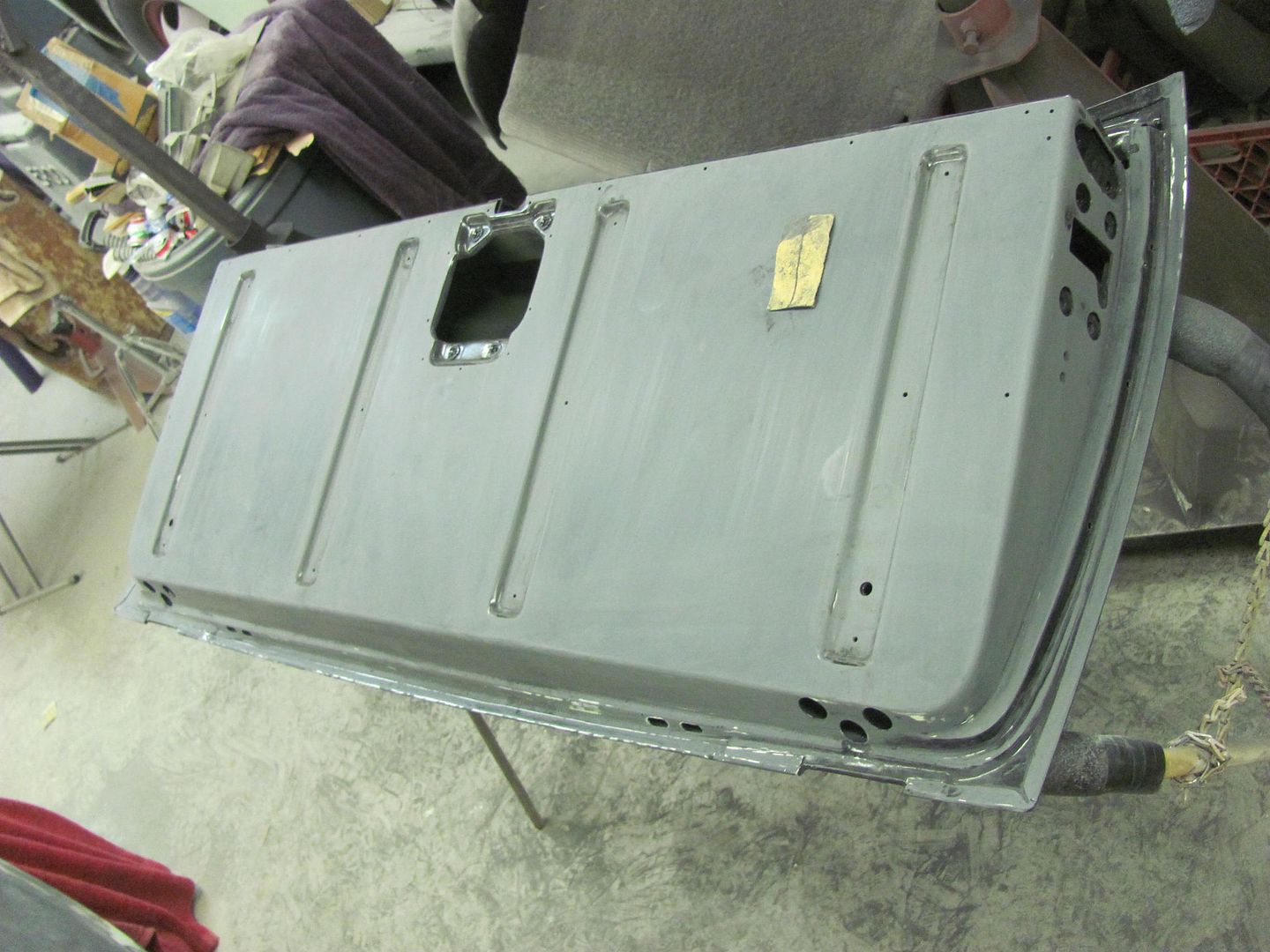
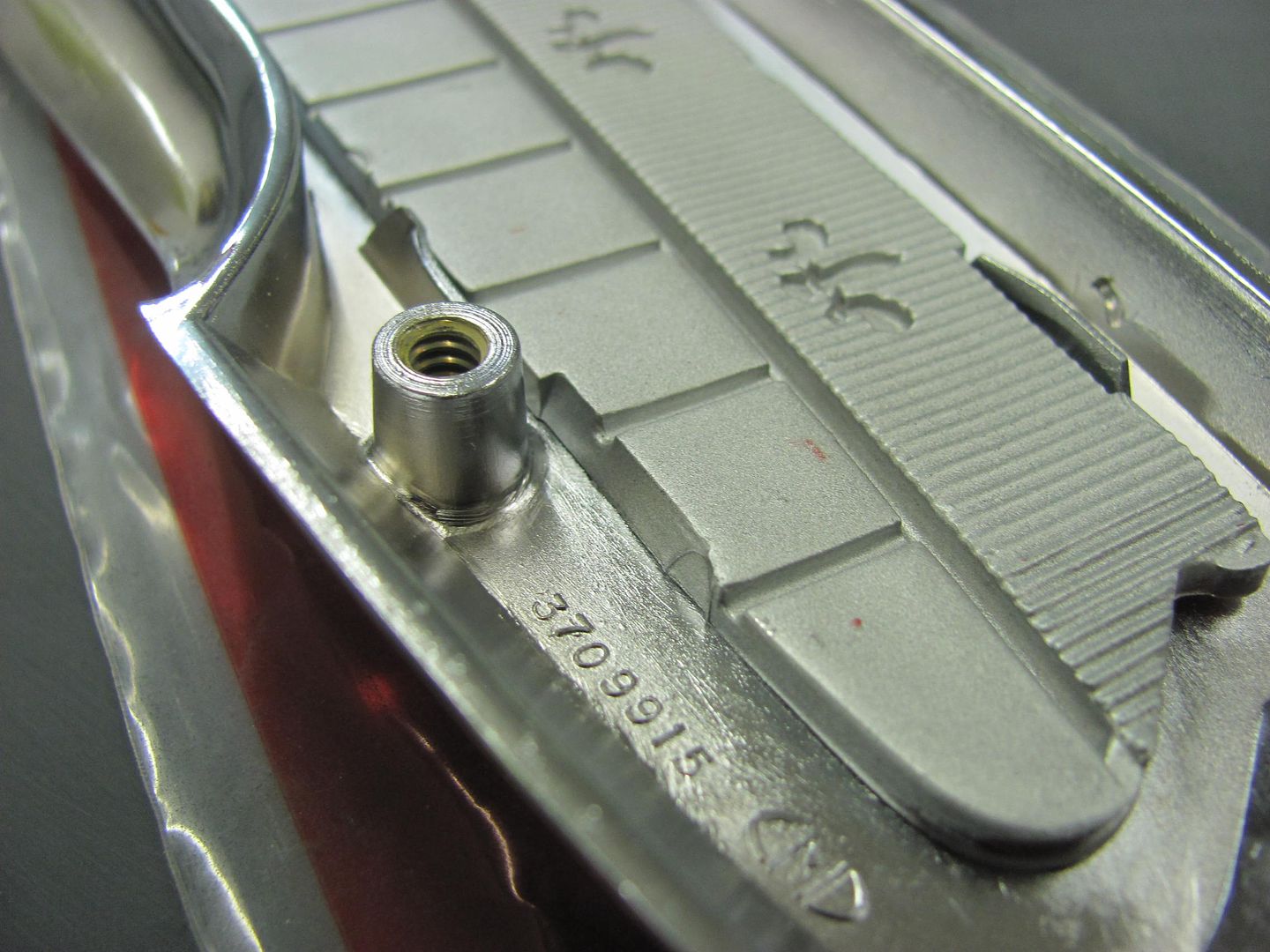
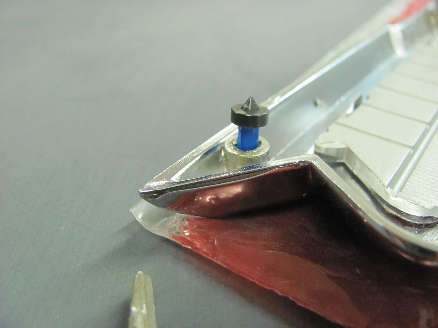
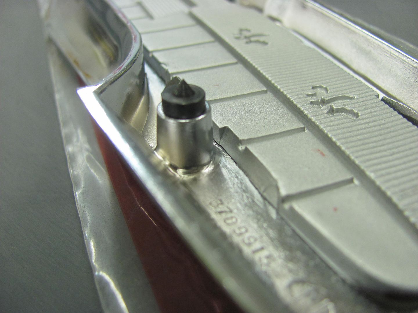
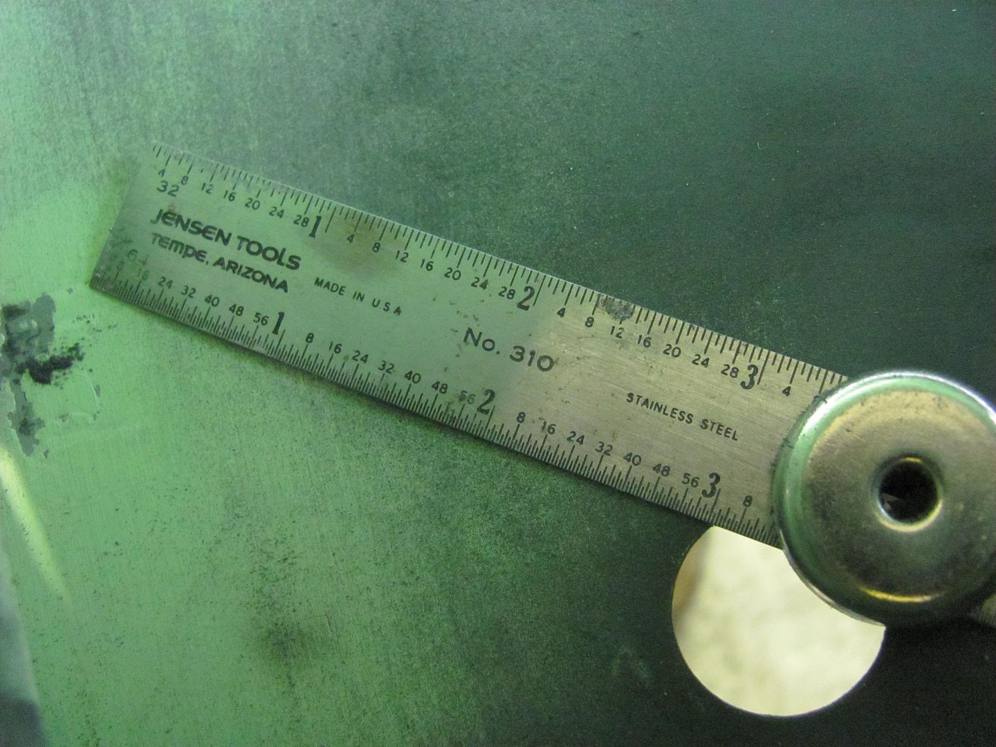
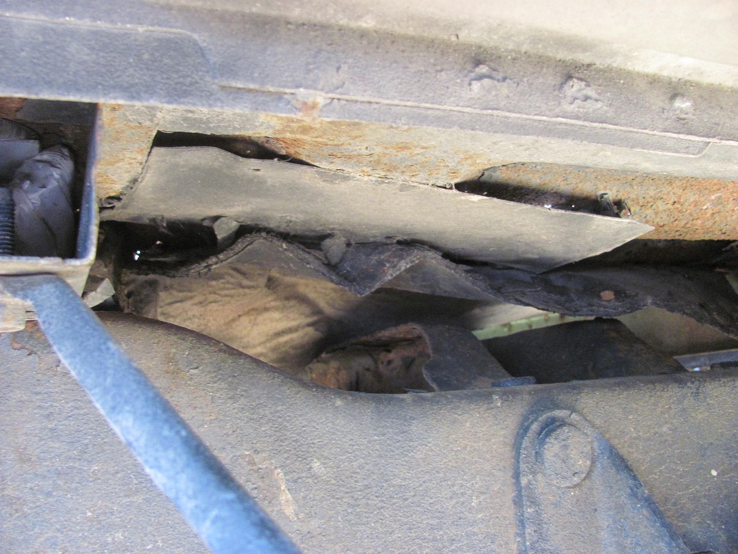
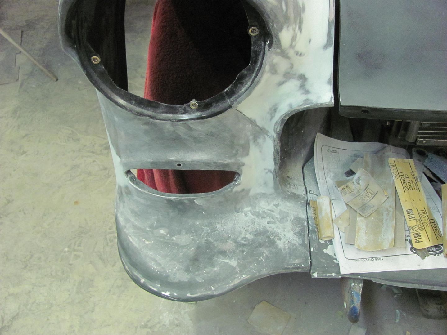
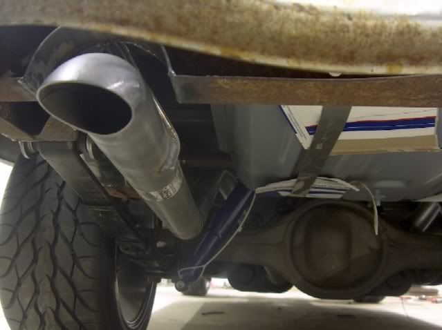
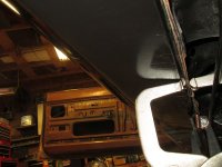
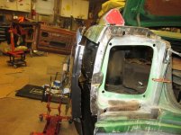
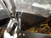
Measuring that distance on the inside shows.....oh wait....what's that bare metal?


Picture%202983.jpg


Picture%202984.jpg


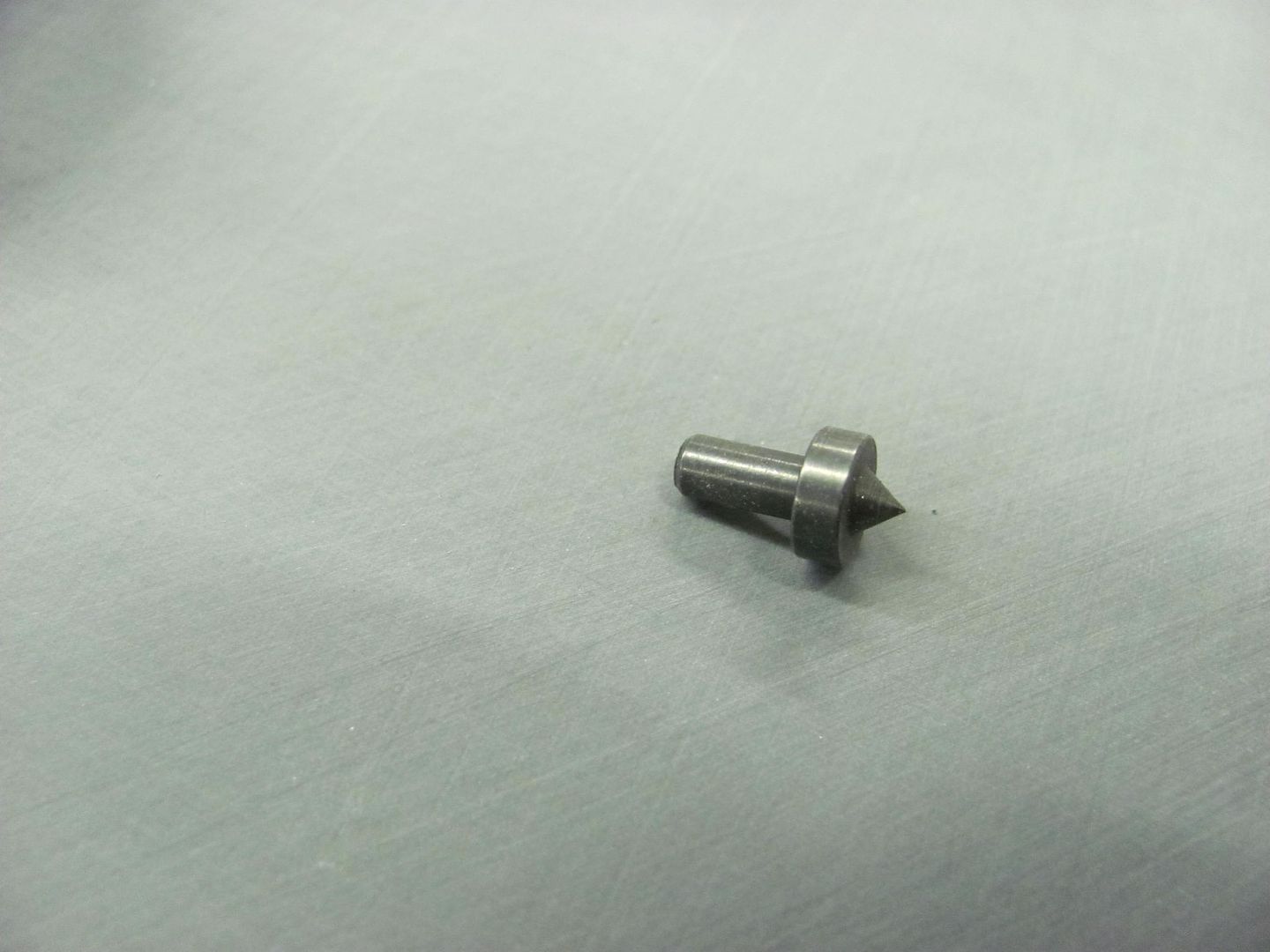
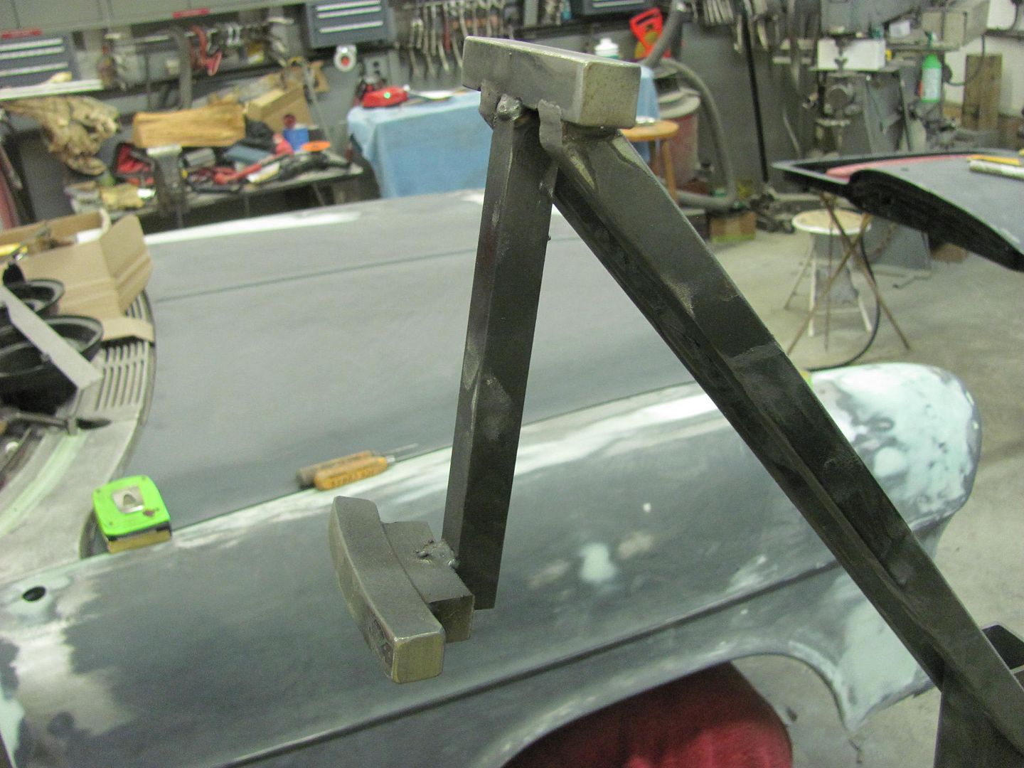
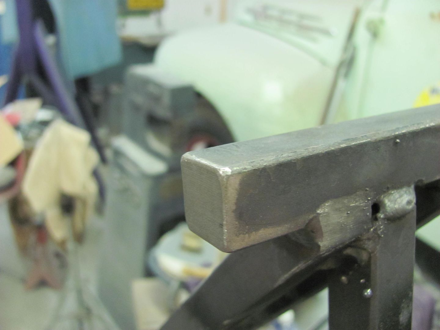
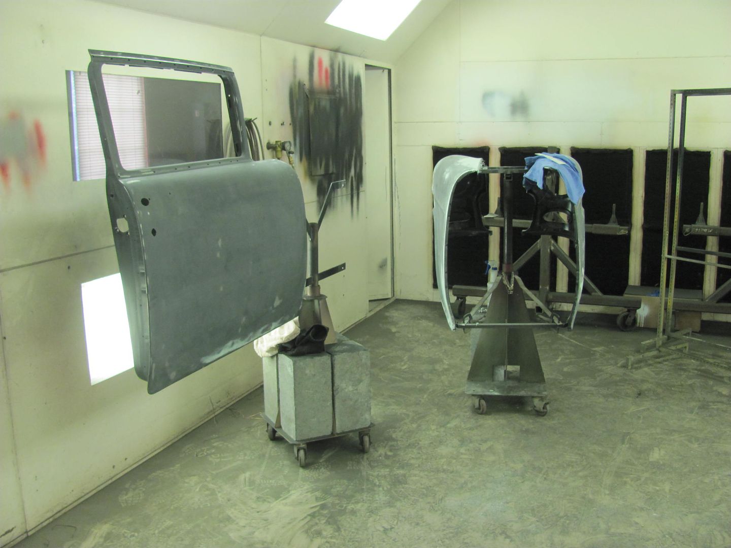
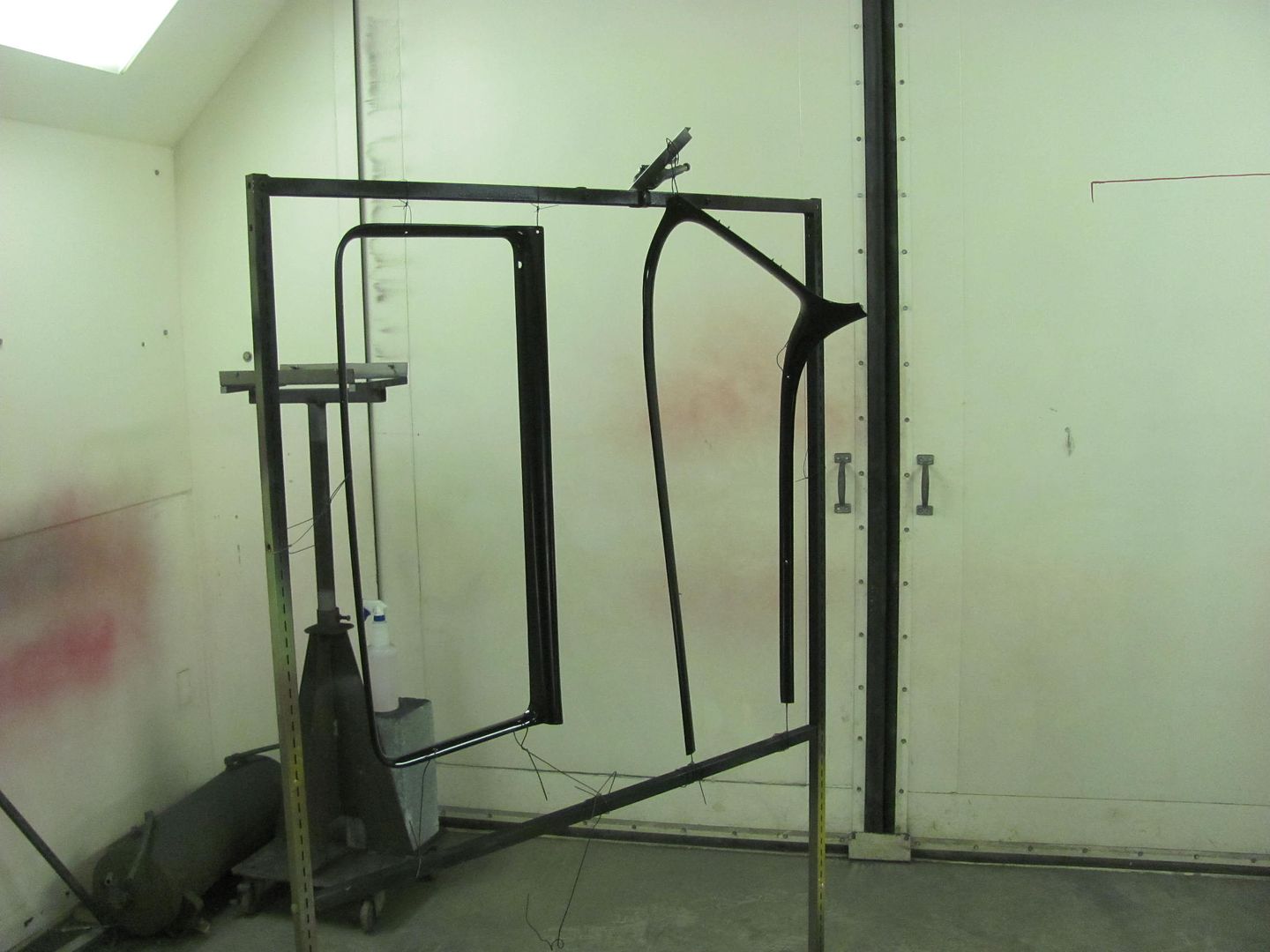
As soon as I saw this I realized there had only been one thing inside that could have caused it... the painting fixture we made..


Picture%202985.jpg


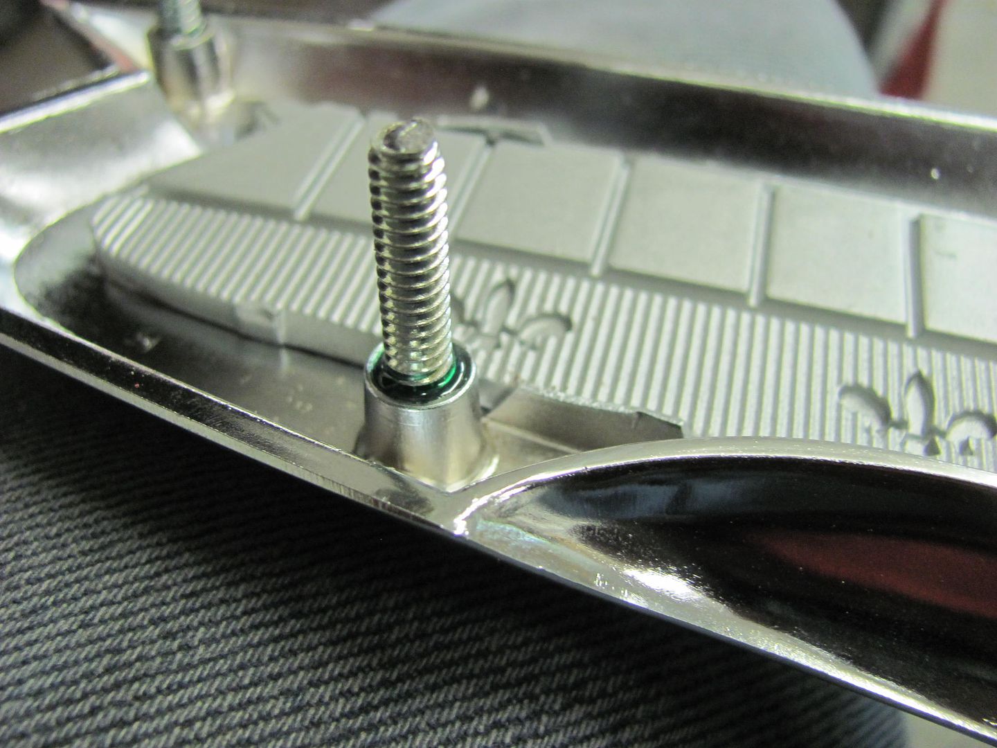
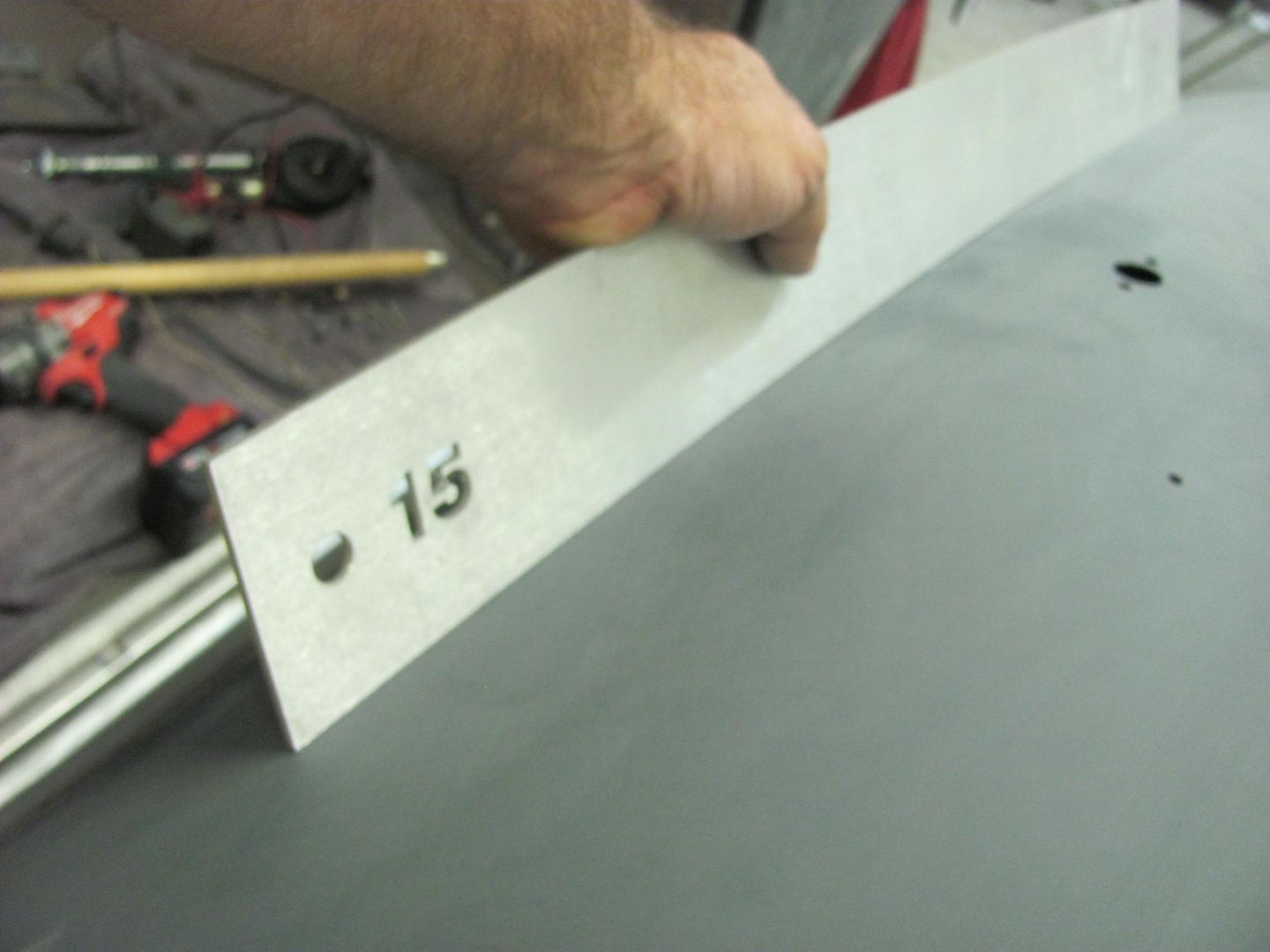
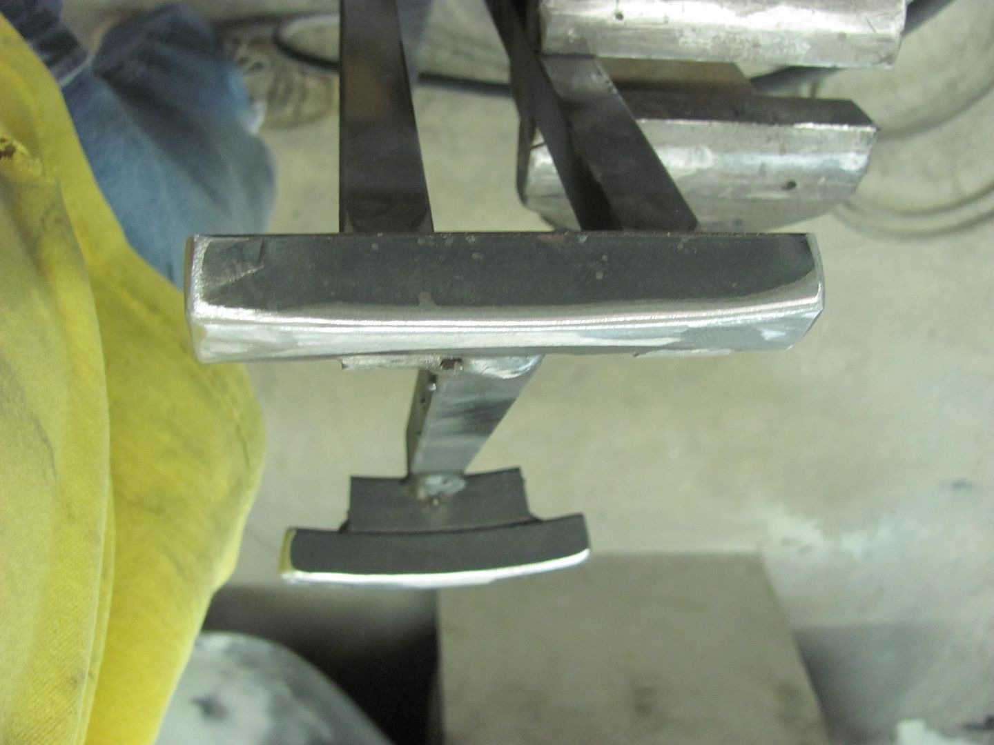
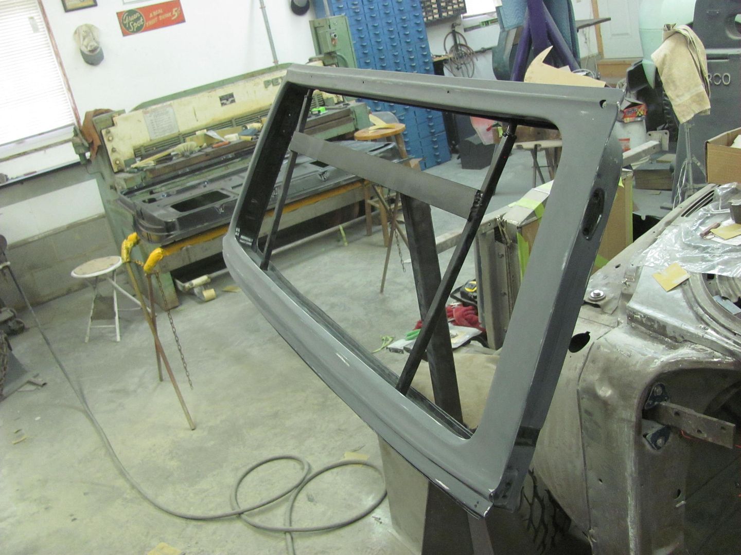
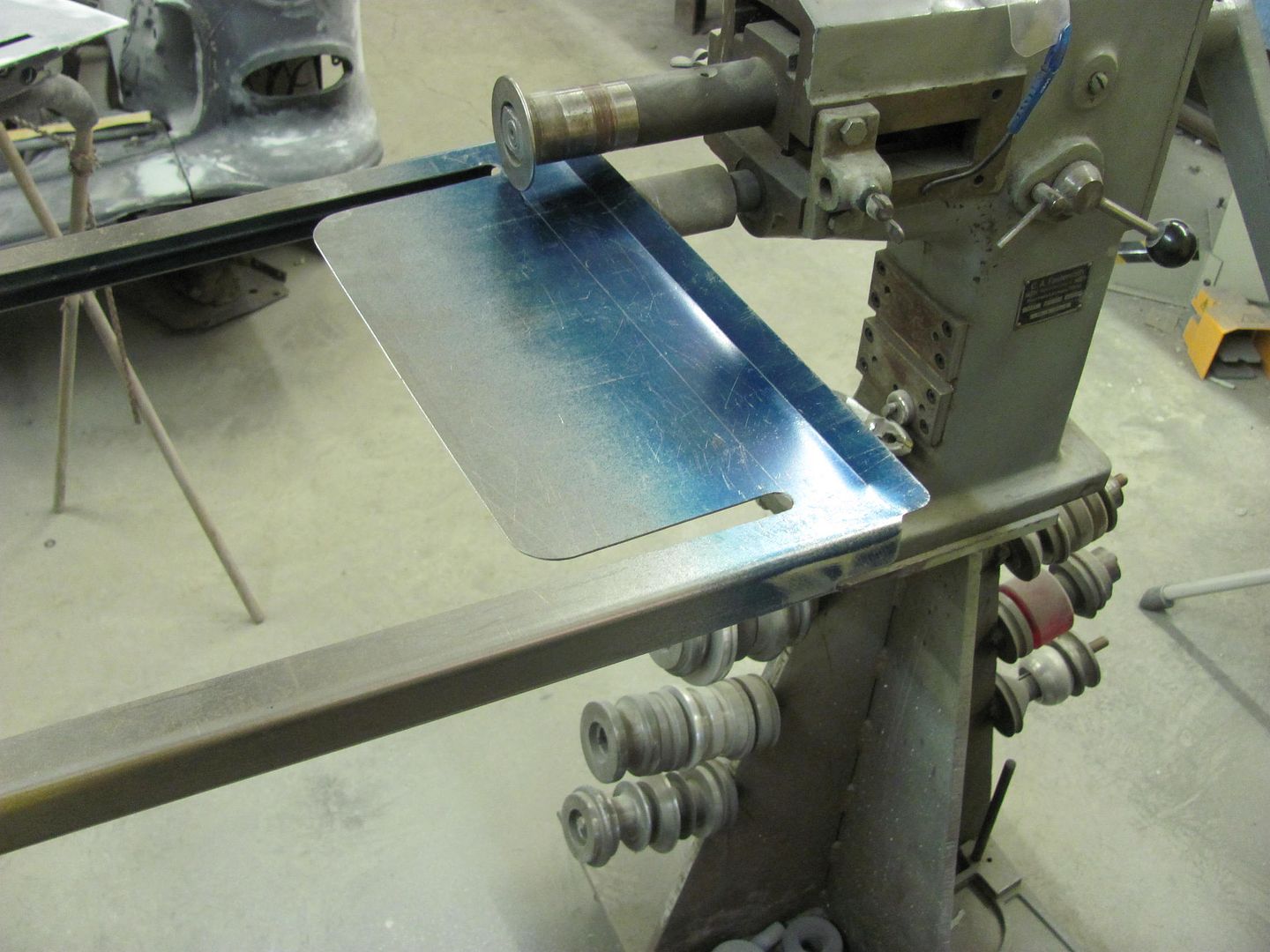
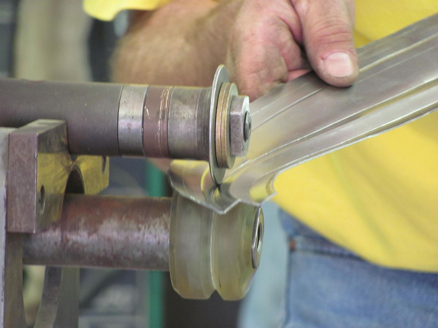
This was made to hold the tail gate in correct alignment as on the car for painting. I had radiused the lower bar but failed to do so on the top one. A check of the skin with body sweeps shows that a #15 sweep is about correct, so it was used to verify some relief grinding on the top bar...


Picture%202986.jpg


Picture%202987.jpg


Picture%202988.jpg


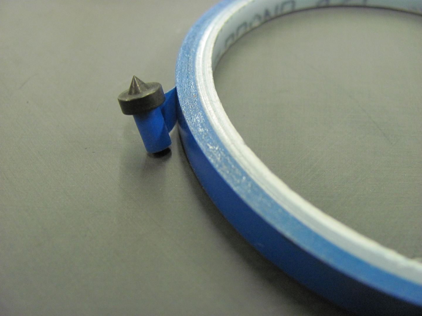
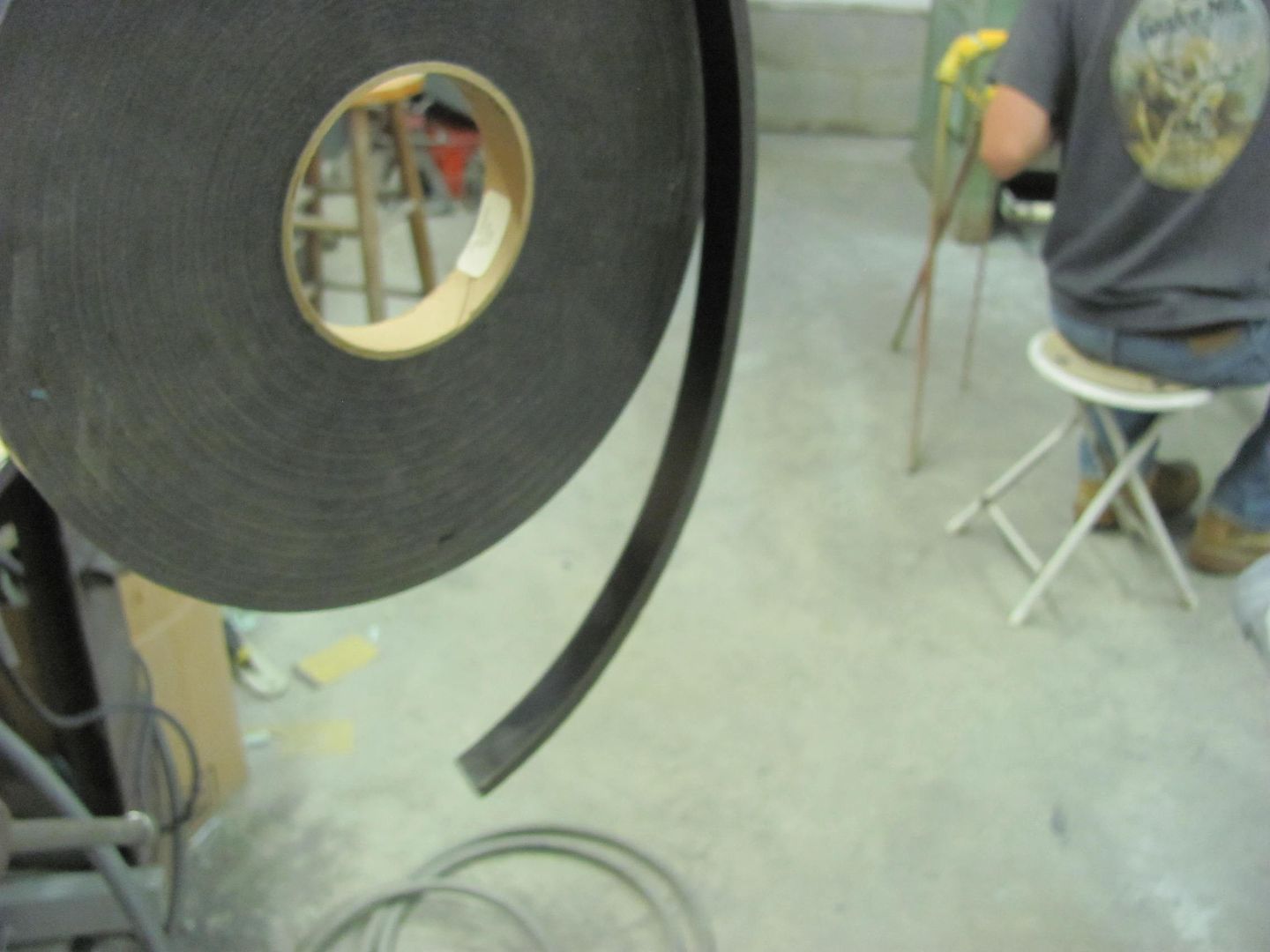
As added insurance, some truck cap gasket seal was added to further isolate the issue on both top and bottom bar....


Picture%202989.jpg


Picture%202990.jpg


On a positive note, glad to find this issue in the primer stage......

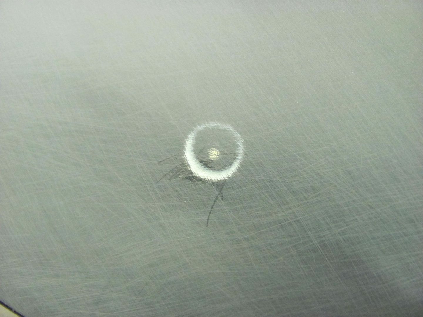
But let's back up a second and look at this picture, it should have been my red flag. Where the second mark to the left in the picture was not as round, looking at it now does show a rather symmetrical device was causing this..


Picture%202940.jpg


So please use my lesson in dumassery to prevent a similar occurrence. :lol: If you're making fixtures to hold body panels insure there are no pointed edges that may cause any outward dings.
 
Last edited:

don long

Well-known member
Joined
Mar 31, 2012
Messages
8,841
Location
southern california
I have used panel holders that used rods coming out of a pole with the ends bent up and found small **** showing up while sanding and it was confusing.
Thanks for pointing that out to us

I use the very same Sata spray guns that you showed and just love them

That cycle paint job looks great
 
OP
M

MP&C

Well-known member
Joined
Oct 21, 2009
Messages
4,396
Location
Leonardtown, MD
Thanks!


Another job in the shop, here's one of the downfalls of the insulation blankets the factory used above exhaust systems...


Picture%202991.jpg


Picture%202992.jpg


Picture%202993.jpg


Nice moisture traps and rust generators. All the used beds found either had similar rust issues or the lower quarters rounded under where the salvage yards had removed them and set them down on the ground. So we went back to the local dealer and ordered the bed floor and new cross members. We have a couple cross members that still haven't arrived, but we can get started in prepping for epoxy primer on the parts we do have..

Scuffing up the floor using 400 grit. Here's the new apprentice for this job, my niece Katie. (her truck) She's not afraid of work and needed little instruction.


Picture%202997.jpg


All scuffed, now to wait on the cross members to come in..


Picture%203002.jpg


Meanwhile Kyle and I have continued blocking body parts for another dose of epoxy...


Picture%202996.jpg


Picture%202998.jpg


Picture%203003.jpg


Picture%203000.jpg
 
OP
M

MP&C

Well-known member
Joined
Oct 21, 2009
Messages
4,396
Location
Leonardtown, MD
Had a request to show some of the mods I did to the rear of the frame for the wagon, so I thought I'd post it in case others may want to see the details as well.


Here's what I did for a shock bar. I didn't care for the trunk floor mounted version of the shock, and preferred an eye on each end, so I used some 1/2-20 grade 8 bolts to make mounting studs. Now this will change your shock pn, the one we used was a NAPA 94018 (made by Monroe) or a Monroe 33086.

The shock bar was made out of 1-3/8 seamless tubing, 1/8 wall thickness. I used a very large uni-bit to drill a hole in the frame for the bar placement. Installing the tube into the frame and using a unibit for a precision hole will get you a nice snug fit for an easier weld and better joint.

Picture469.jpg


Picture473.jpg


The factory shock plates for the bottom of the leaf springs had a 5/8 sleeve, so this was cut off. A 1/2 hole was drilled, the 1/2-20 bolt cut off to length and installed about halfway throught he plate thickness. The remaining hole was plug welded full, and a strengthening gusset added to the back side. Using some 1/2 sch 80 pipe, a shoulder was added for the shock to rest against.


Picture481.jpg


Picture482.jpg


Picture483.jpg


As you can see we put the shocks on the back side of the rear, so the plates were merely swapped from one side to the other.

For the top mounting stud, a 1/2 hole was drilled in the front side of the tube, and a 3/8 hole in the back. The 1/2-20 bolt was cut to length, and pushed against the 3/8 hole. This was plug welded closed, and a weld bead done around the stud on the other side. Once again, a piece of 1/2 sch 80 pipe was used to provide a shoulder for the shock to rest against, and hold it out from the horizontal tube.


Picture484.jpg


Picture485.jpg


Picture486.jpg


Picture487.jpg


Picture498.jpg


Picture138.jpg


Picture134-1.jpg
 
OP
M

MP&C

Well-known member
Joined
Oct 21, 2009
Messages
4,396
Location
Leonardtown, MD
Here's the exhaust routing showing the relief cuts in the rear cross member. This was done using a Flowmaster kit, all the joints were **** welded and ground smooth, then powder coated when done.

HPIM4917.jpg


HPIM4923.jpg


HPIM4924.jpg


HPIM4930.jpg


Also used v-band clamps. These are the steel version, available from Jegs or Summit


Picture128.jpg


Picture125.jpg


Picture138.jpg


Picture516.jpg


Picture513.jpg


Picture514.jpg


Rear cross member relief cut "ring" was formed out of 16 ga cold rolled steel.


Picture515.jpg


Picture519.jpg


From the rear the exhaust is not visible, as it should be....


Picture511.jpg
 
Last edited:
OP
M

MP&C

Well-known member
Joined
Oct 21, 2009
Messages
4,396
Location
Leonardtown, MD
Larry, jack stands were under the front end and rear axle, and I didn't have another matched set of stands to hold up the exhaust parallel to the ground. So that's where the cinder blocks came into play......not holding up the car, just getting the pipes up long enough to c-clamp a bar across to hold them for tacking.... But thanks for keeping me honest.... ;)
 

Chevyman for life

New member
Joined
Jul 20, 2015
Messages
1
Location
Montana
Robert,
I was having withdrawal symptoms with not finding your projects on the other forum.

Found it yesterday here - so glad to find it. You've been an inspiration for about the last 8 years.
 
To avoid these ads, REGISTER NOW!
Top Bottom