
You are using an out of date browser. It may not display this or other websites correctly.
You should upgrade or use an alternative browser.
You should upgrade or use an alternative browser.
MP&C Shop Projects
- Thread starter MP&C
- Start date
Strouty
Well-known member
Merry Christmas Robert, hope you get some quality family time.
xtremek
Well-known member
Happy Christmas. May it be nothing but great memories.
Bob Heine
ALLIANCE MEMBER
Robert, thank you for filling my stocking to the brim with all your posts. I try not to fill your thread with my WOWs but know I have them stacked up for you.
Wishing you and yours a Merry Christmas and many more Happy New Years.
Wishing you and yours a Merry Christmas and many more Happy New Years.
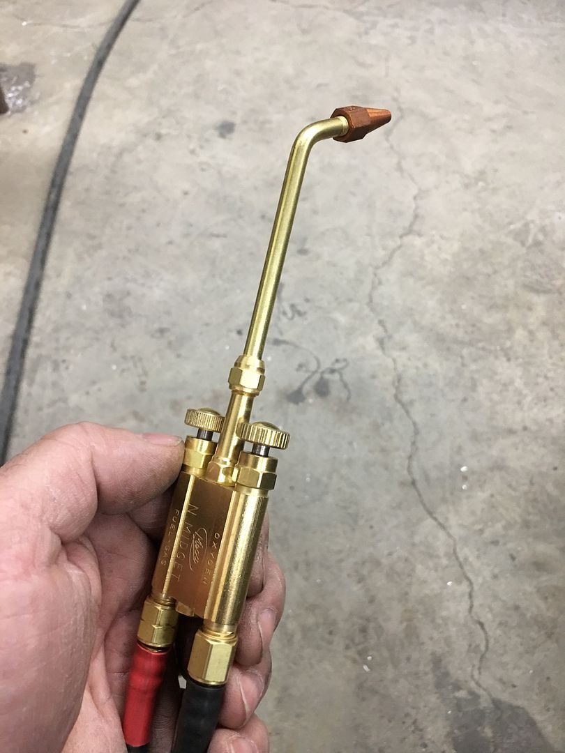
Got a new addition to the shop, this Meco came from TM Technologies, or TinManTech. I got it hooked up last night and ran a couple passes.
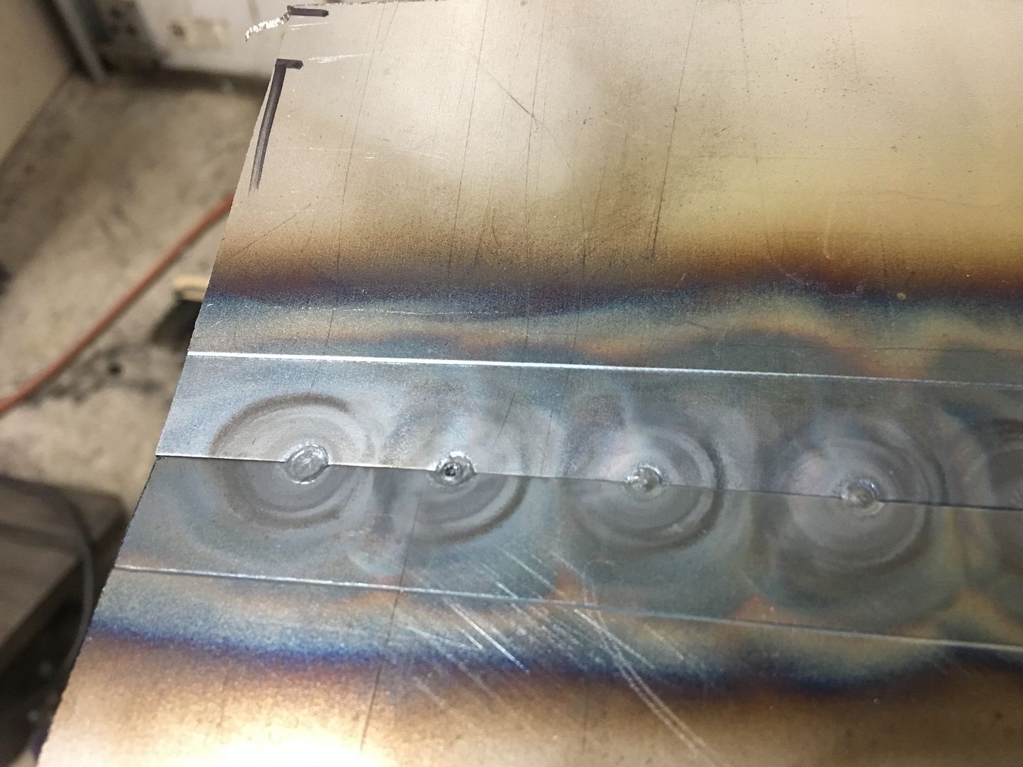
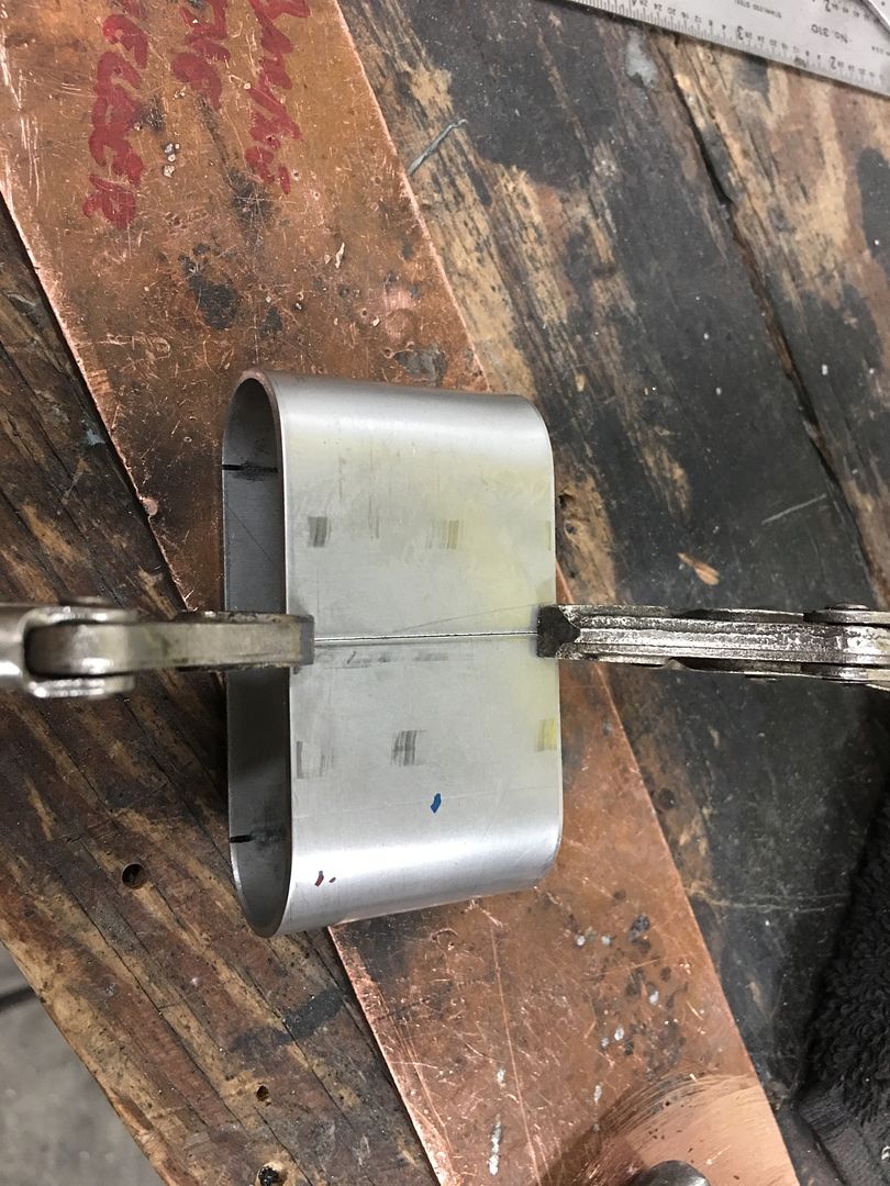
Let me start by saying I am not a gas welder. I have a Henrob torch that I have found awkward to use, likely the operator, so I have instead always used MIG or TIG. This video shows my second attempt with the Meco, the first attempt I did not have sufficient heat as I was worried about blowing holes. The two “scraps” were picked off the floor and tacked together about every 3/4”, then fusion welded the distance shown, yielding a full penetration weld with nice HAZ conisistency. Very impressed with the light weight and ease of use, even for an old dog learning new tricks. Video shows in order: front, back, planished, and bent at 90* for our destruction test.
Tacks, front side..
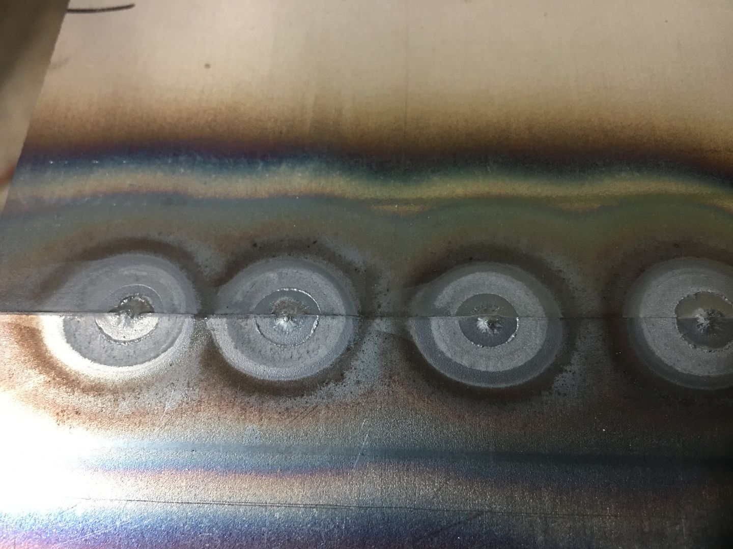
Rear side, full penetration...
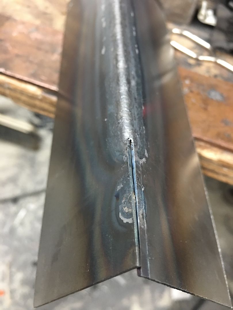
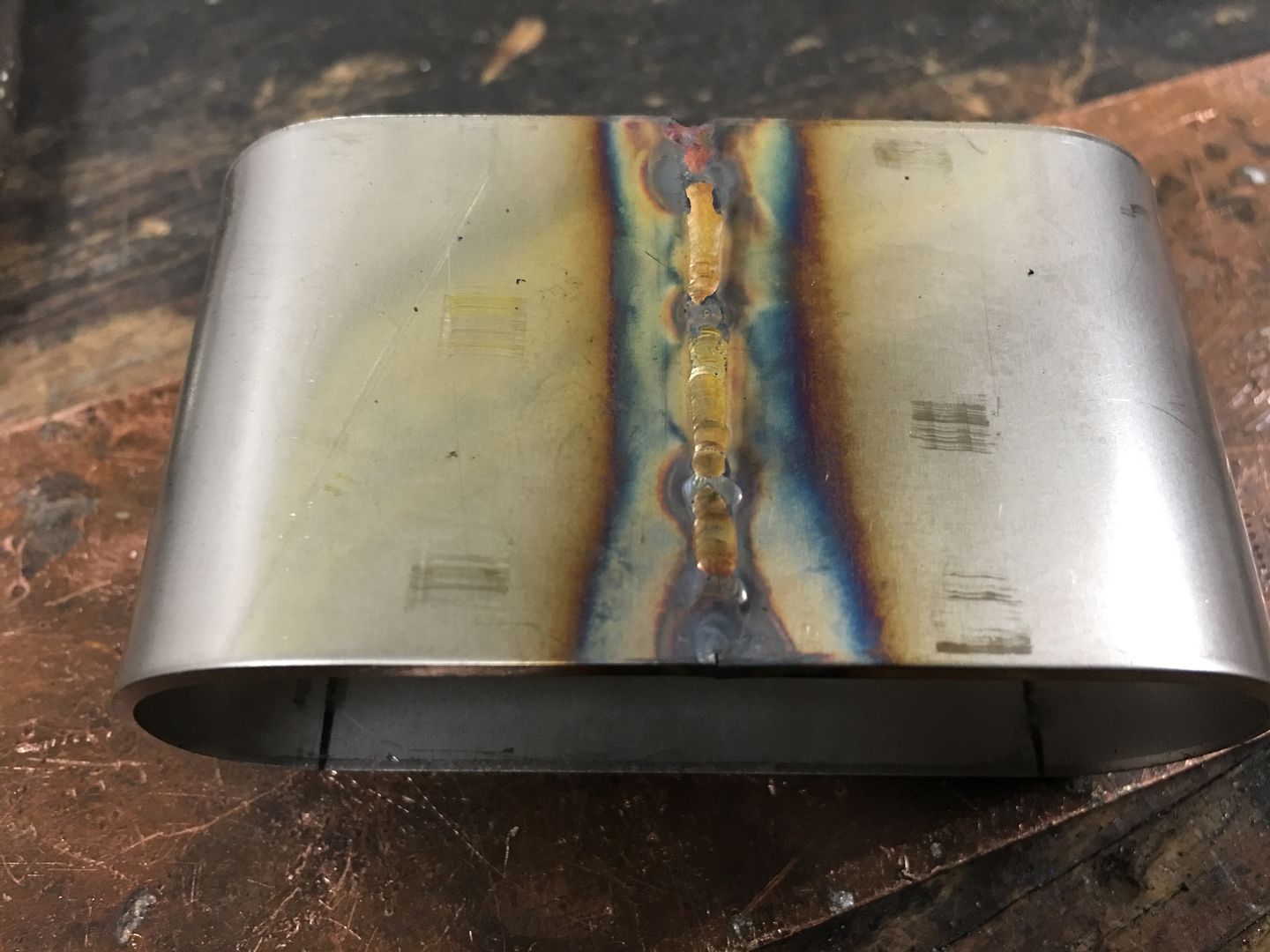
Full pass with full weld penetration, bent 90* for destruction test.. Line shown is mark left by press brake die....

Rear side held up well
Very impressed with this torch, one handed valve adjustments are a breeze, light weight and easy to use..
Let me start by saying I am not a gas welder. I have a Henrob torch that I have found awkward to use, likely the operator, so I have instead always used MIG or TIG. This video shows my second attempt with the Meco, the first attempt I did not have sufficient heat as I was worried about blowing holes. The two “scraps” were picked off the floor and tacked together about every 3/4”, then fusion welded the distance shown, yielding a full penetration weld with nice HAZ conisistency. Very impressed with the light weight and ease of use, even for an old dog learning new tricks. Video shows in order: front, back, planished, and bent at 90* for our destruction test.
Tacks, front side..
Rear side, full penetration...
Full pass with full weld penetration, bent 90* for destruction test.. Line shown is mark left by press brake die....
Rear side held up well
Very impressed with this torch, one handed valve adjustments are a breeze, light weight and easy to use..
Last edited:
xtremek
Well-known member
If that's not a good weld, I'm totally ashamed of what I do.
larry4406
Well-known member
Nice Robert!
What does the Meco allow you to do that the MIG or TIG cannot?
What does the Meco allow you to do that the MIG or TIG cannot?
This would provide about the softest weld going, (with MIG being the hardest) for an easier job of planishing. It doesn't have anywhere near the cleanup when using the fusion weld, the only thing done was planishing. For joining aluminum panels, this torch allows a good full penetration weld where using the TIG normally does not have a good weld on the back side and requires another pass to address.
This, along with the ultra lightweight hose, make it easy to use and maneuver, one hand adjustments, and the welding I did last night was actually enjoyable. No grinding, no touchups on the back side, etc. Note the fairly consistent HAZ as well, key for minimizing distortion. This and TIG are about the only method going for doing a full pass weld or even a full pass fusion weld, for the least amount of distortion. I think the softer flame of the O/A torch is less likely to have blowouts that one might experience with the TIG. For those on a budget, the torch, hoses, and a set of tips was under three bills delivered. For someone just starting in automotive sheet metal repair, this would give just as nice a finish as any other method, less cleanup work as compared to MIG, and go easy on the budget.
This, along with the ultra lightweight hose, make it easy to use and maneuver, one hand adjustments, and the welding I did last night was actually enjoyable. No grinding, no touchups on the back side, etc. Note the fairly consistent HAZ as well, key for minimizing distortion. This and TIG are about the only method going for doing a full pass weld or even a full pass fusion weld, for the least amount of distortion. I think the softer flame of the O/A torch is less likely to have blowouts that one might experience with the TIG. For those on a budget, the torch, hoses, and a set of tips was under three bills delivered. For someone just starting in automotive sheet metal repair, this would give just as nice a finish as any other method, less cleanup work as compared to MIG, and go easy on the budget.
Last edited:
EdT
Well-known member
I have MECO that a buddy of mine gave me several years ago. I love it and use it a lot, mostly for silver soldering and brazing on light fabrications. I've never used it for welding steel, but I may give it a try. What size tip did you use for your test? It is a preferred way for welding aluminum sheet metal. Just picked up another one at a sale along with a gas saver valve which will come in handy for repetitive operations.
1953mercury
Well-known member
I can see the advantages. Do you know if it's possible to get the same result using propane instead of acetylene, to keep the operating cost down? Thanks, Mike
...........What size tip did you use for your test? It is a preferred way for welding aluminum sheet metal...........
I used an N1 premium tip.. Yes, you are correct that it is ideal for welding aluminum sheet. Where TIG will give a nice clean weld, you will only get that on the weld side, in most cases the back side of a TIG weld will need a weld pass as well. The gas weld gives a good weld bead on both front and back in one pass, making it the preferred choice of most aluminum coach builders.
......... Do you know if it's possible to get the same result using propane instead of acetylene, to keep the operating cost down? Thanks, Mike
A local jeweler that I know has the same torch that he has owned for 42 years, still in use today. He does use Propane for his torch, he says it is cheaper but also cleaner for jewelry work. I think it may require tips specific for propane.
I was asked to bend the weld sample to a complete 180* to give the weld a "REAL" test. So the following video does such, please excuse the erratic movement of the camera operator, he also had to close the vise and position the sample..
gofastwclass
Well-known member
Wow! I wonder what you'll accomplish once you actually feel comfortable with this new tool?
I wanted one of those torches for a while but I didn't realize how valuable it could be and placed it a little lower on the priority list than it should have been. I'll have to seriously consider one now. Thanks for sharing.
I wanted one of those torches for a while but I didn't realize how valuable it could be and placed it a little lower on the priority list than it should have been. I'll have to seriously consider one now. Thanks for sharing.
larry4406
Well-known member
This would provide about the softest weld going, (with MIG being the hardest) for an easier job of planishing. It doesn't have anywhere near the cleanup when using the fusion weld, the only thing done was planishing. For joining aluminum panels, this torch allows a good full penetration weld where using the TIG normally does not have a good weld on the back side and requires another pass to address.
This, along with the ultra lightweight hose, make it easy to use and maneuver, one hand adjustments, and the welding I did last night was actually enjoyable. No grinding, no touchups on the back side, etc. Note the fairly consistent HAZ as well, key for minimizing distortion. This and TIG are about the only method going for doing a full pass weld or even a full pass fusion weld, for the least amount of distortion. I think the softer flame of the O/A torch is less likely to have blowouts that one might experience with the TIG. For those on a budget, the torch, hoses, and a set of tips was under three bills delivered. For someone just starting in automotive sheet metal repair, this would give just as nice a finish as any other method, less cleanup work as compared to MIG, and go easy on the budget.
Thank you Robert.
With the MIG on sheet metal **** joints you were doing the tack, planish, tack, grind, repeat thing which you have explained quite well yielding excellent results. Process seems quite tedious.
With this MECO what would be the approach for a **** joint on say a quarter panel? Same tight **** joint fit-up, several tacks spaced some distance apart (1-2 inches?) for the full length of the seam, placing tacks in succession working from one end to the other vs from the ends toward the middle (the latter I would think would capture a warp), then go for broke and fusion weld the full length?
I seem to remember you or someone else demonstrating this at OJ's Clark County rod shop in Berryville VA back in 2013 when he hosted a metal meet there and you and several other very talented folks gave demonstrations. Or maybe it was at a Gater meet.
The main limiting factor with using the MIG is having enough heat that you have a full penetration weld with the first tack. Normally this means you aren't doing a weld pass, as once the panel heats up you wind up blowing holes. So yes, the process that I have used is slow, monotonous, but provides a viable option for those using the point and shoot of the MIG. I feel that once a person becomes fluent in trimming panels for a tight fit, which I would suggest for any weld process used, then the subsequent weld process and cleanup afterward is the only variable. MIG provides the most shrinking based on all the starting and stopping, and to maintain consistency in efforts, is approx. 3 to 4 times the work. Keep in mind the "work" would also involve any planishing, grinding, and panel bumping to straighten out any distortion left by our weld process. TIG or O/A allows us better heat control to be able to perform a non-stop weld across the panel (or as far as our skillset permits) to eliminate much of the start-stop areas and the puckers that form in these locations.
You are correct in your assessment of the process for the full weld pass, start at one end of the panel, align and tack as you go, working from one end to the other. Do not skip around as so many people suggest, as yes, this risks panel mis-alignment. If the panel starts to close up as you tack, planish the last tack to open the panel back up. For using the O/A, the way Peter Tommasini teaches tacking never mentions how many inches / specified distance between tacks but instead to place the second (subsequent) tack where the outer perimeter of the HAZ from the tack just completed touches the seam. I believe the theory here is to give as close to consistent a HAZ as possible, even in the tacking stage. Then once all the tacks are complete, and planished as needed to align panels flat, a continuous/non-stop (as far as we are able) weld seam will gradually heat the panel as we work our way across, and gradually cool in the same fashion. This gives us less puckers from start/stop, but also more equalized forces exerted as any shrinking should be consistent from one end to the other. So although the panel may shrink, in theory it should be a consistent shrink such that the panel is not full of waves like the Atlantic Ocean. All in an attempt to give us less work in the "straighten the panel" phase. It is ALL part of the weld process, IMO.
So for someone doing panel replacement and trying to live within a budget, a small torch like this one is going to be easier on the wallet than a MIG, and given proper technique, yield better results and take less time doing so. If my camera (phone) will cooperate behind the spare helmet this weekend, I may attempt a video showing the tacking and fusion weld process.
Toothaker
Well-known member
I'm tempted to call you Professor... ")
Will the MECO work with a regular O/A rig? That is, do the regulators and hose from a quality medium duty O/A outfit connect and work with the MECO, or does it need its own rig?
Your thread is consistently one of the most educational ones on GJ.
Will the MECO work with a regular O/A rig? That is, do the regulators and hose from a quality medium duty O/A outfit connect and work with the MECO, or does it need its own rig?
Your thread is consistently one of the most educational ones on GJ.
larry4406
Well-known member
I'm tempted to call you Professor...
Will the MECO work with a regular O/A rig? That is, do the regulators and hose from a quality medium duty O/A outfit connect and work with the MECO, or does it need its own rig?
Your thread is consistently one of the most educational ones on GJ.
+1000!
I have the same questions.
If your regulators don’t play nice at lower pressures, ie around 5 or so, then you may need different regulators. The Meco has smaller fittings than your standard torch but TBH trying to use those larger hoses on a torch this size kinda defeats the purpose. Why add bulk so it’s harder to use? The TinManTech site sells the ULW hose set that comes with adapters to use on the regulator end so you can use your present bottles/regulators.
bradpac
Well-known member
Would a mini bottle set work well with this setup or does it go through quite a bit of gas? I have quite a few trim holes and a little rust repair to do on the bed side of a truck as an example of a typical job for me.
A little portable setup like this.

A little portable setup like this.
Best wishes to everyone for a healthy and prosperous New Year!
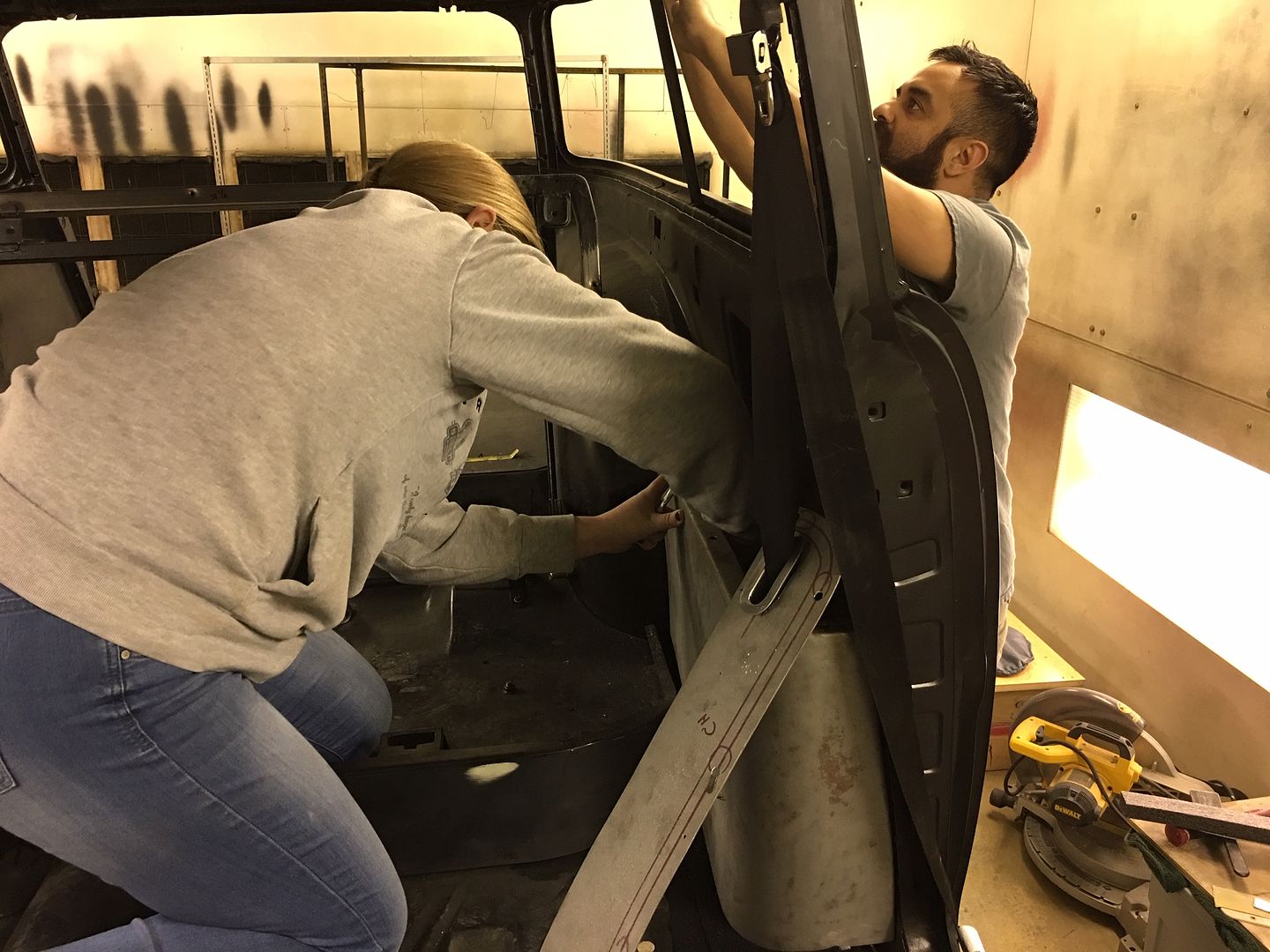
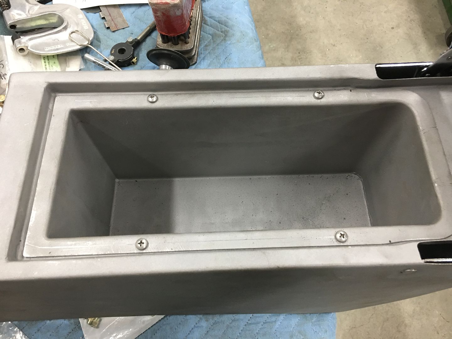
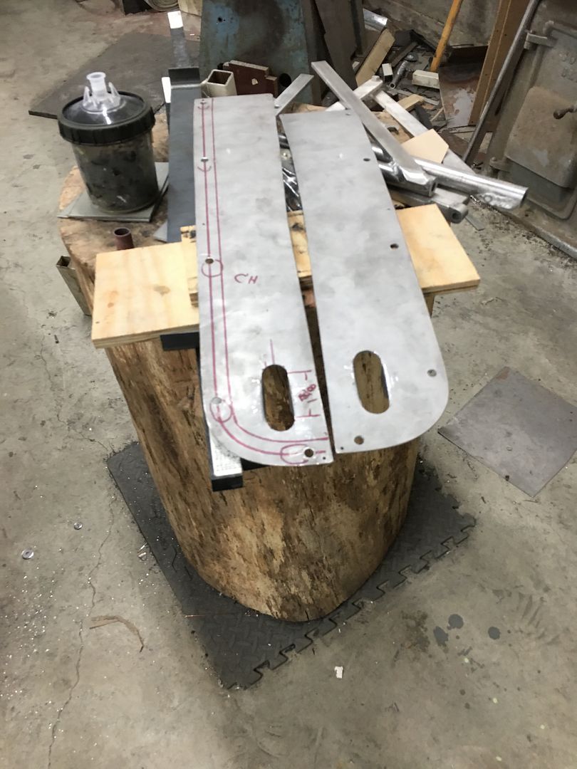
Some wagon updates, we've been tying up loose ends to get parts ready for upholstery and the roof ready for paint. With the arm rest details ironed out, E is unbolting the kick panels so we can cut out the speaker holes. Mike is getting the roof skin blocked out..
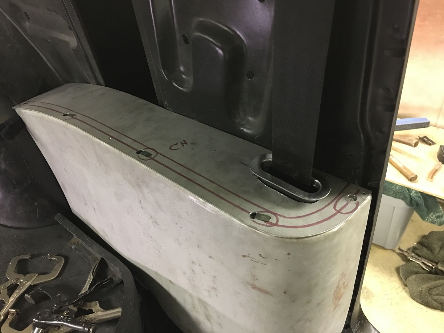
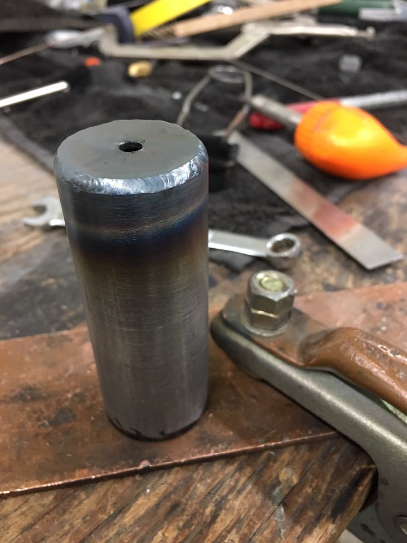
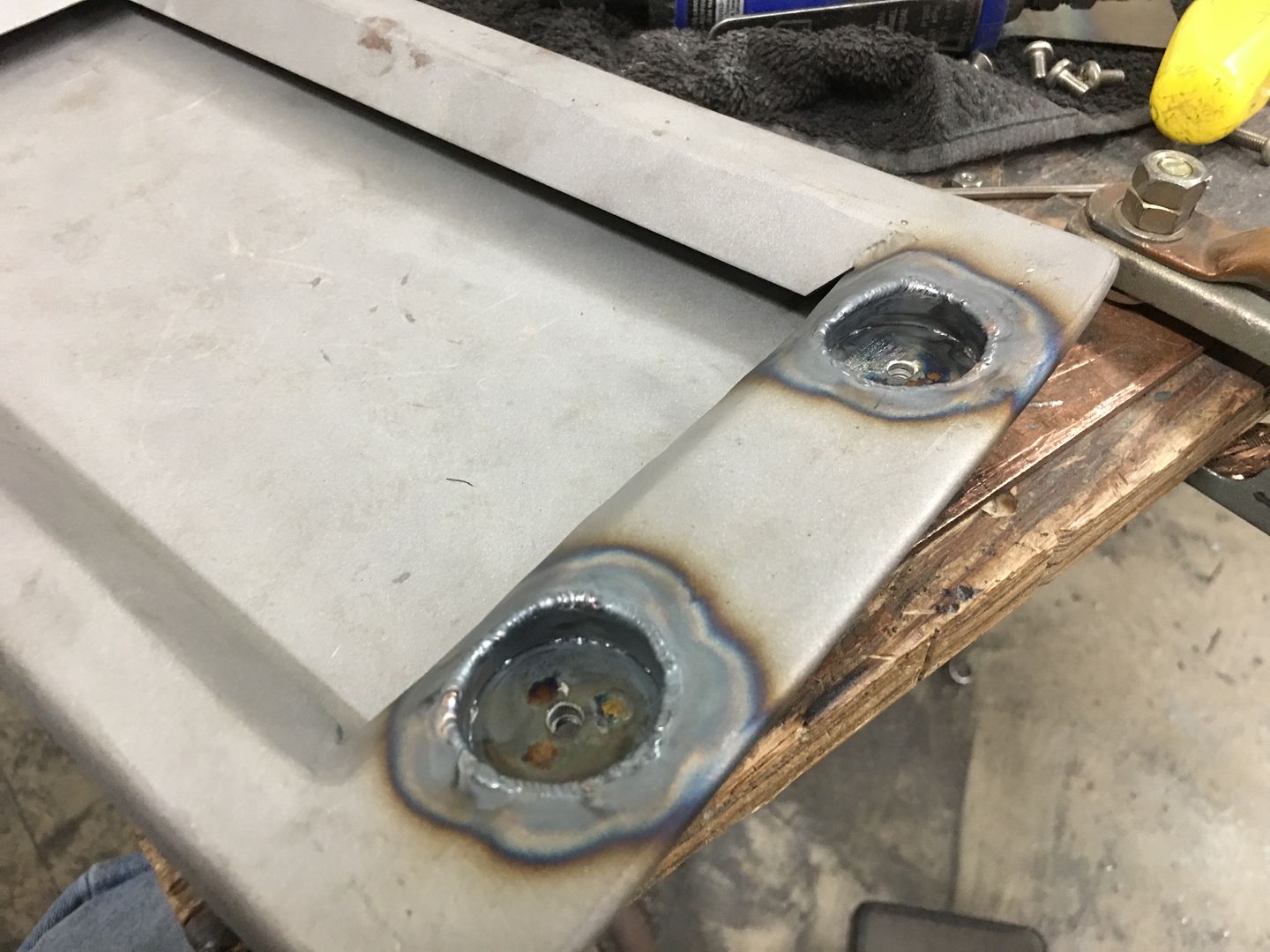
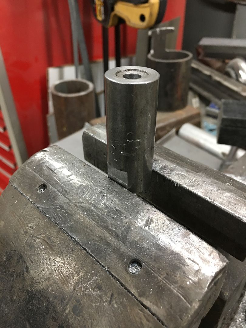
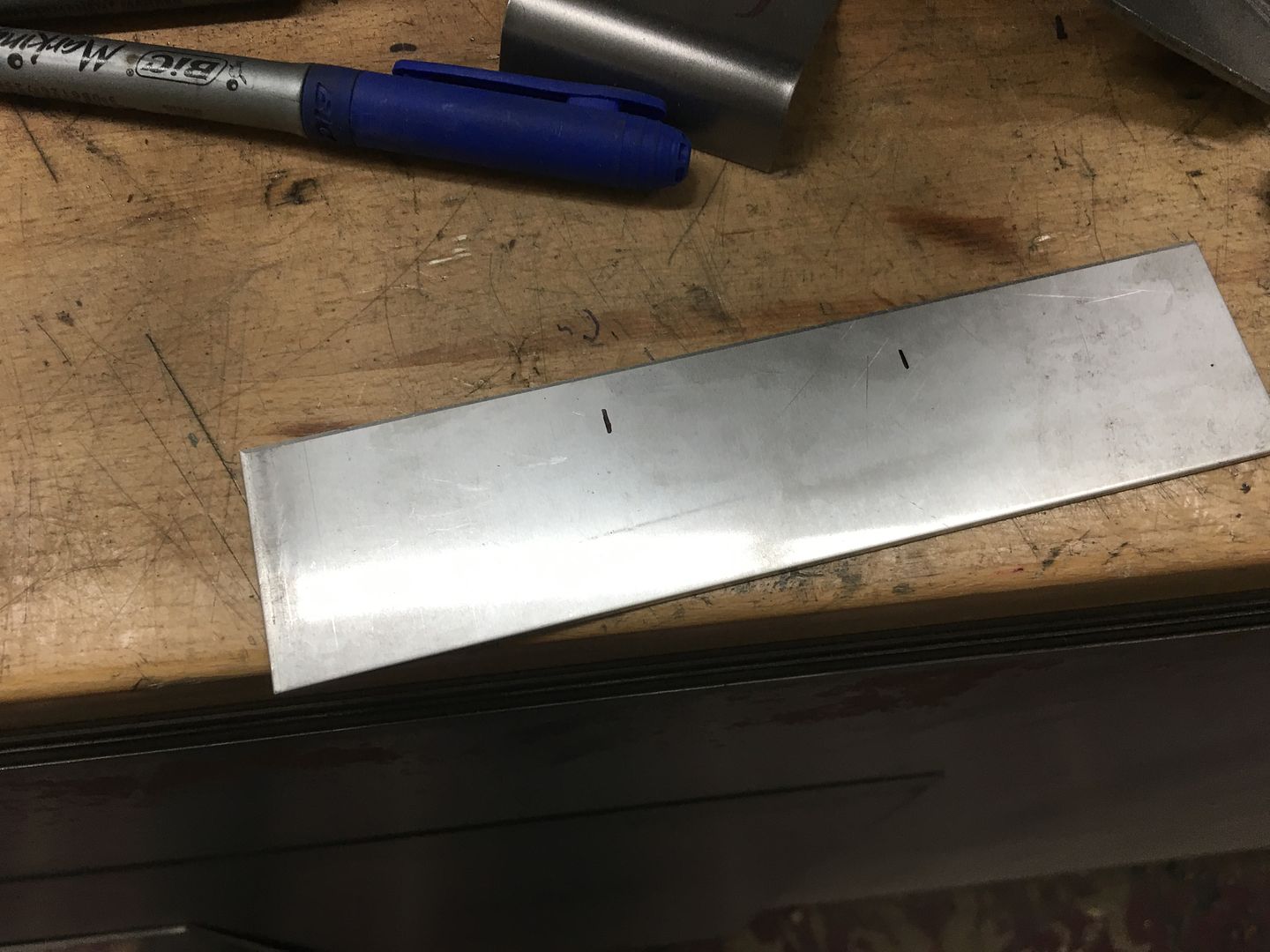
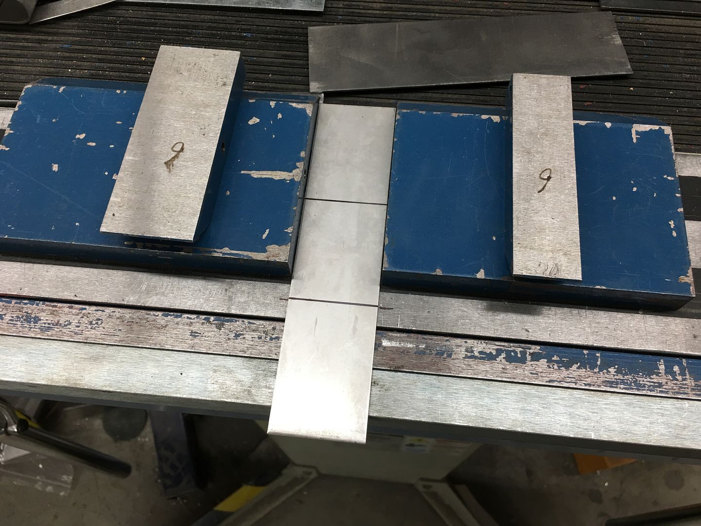
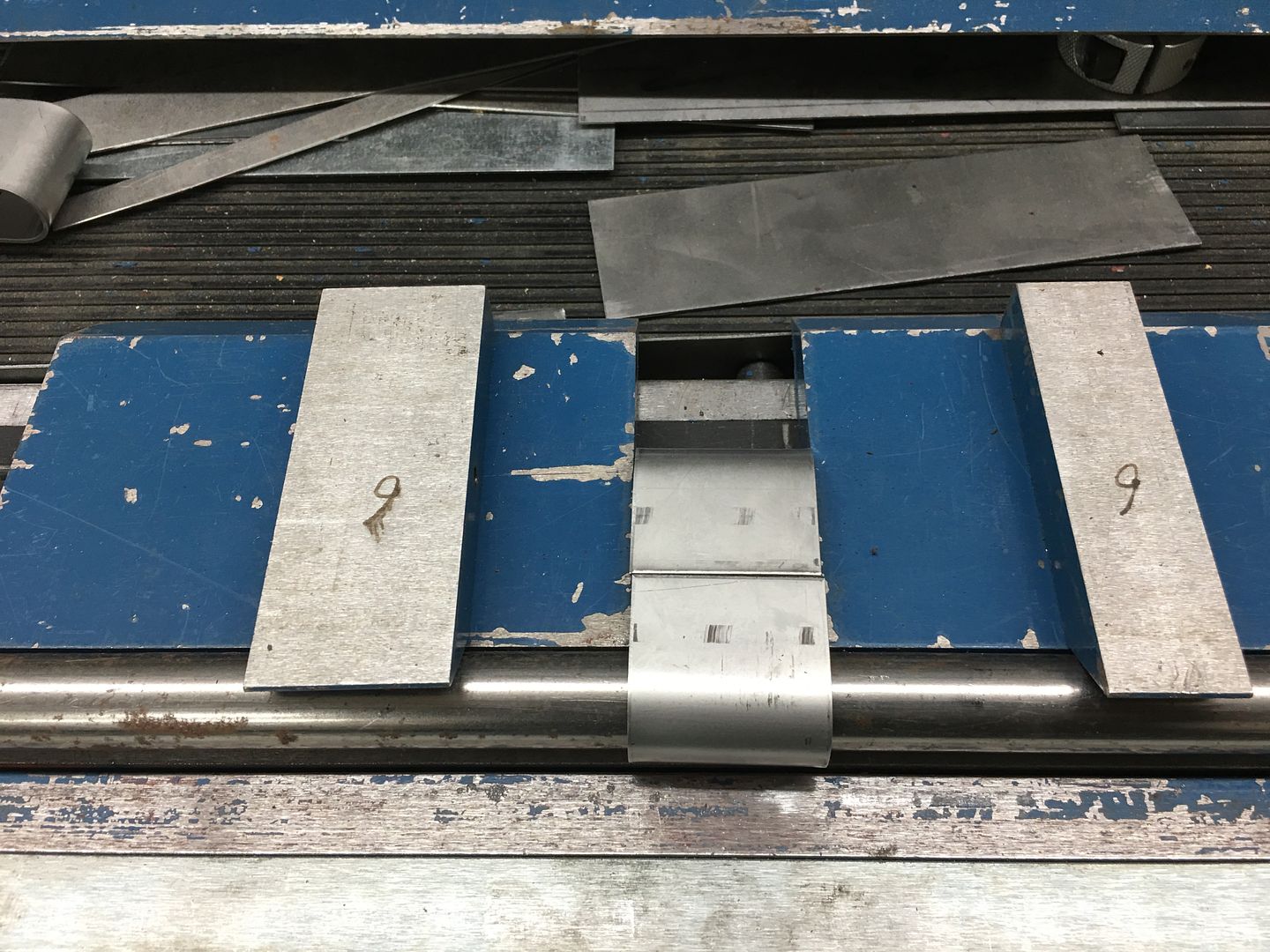
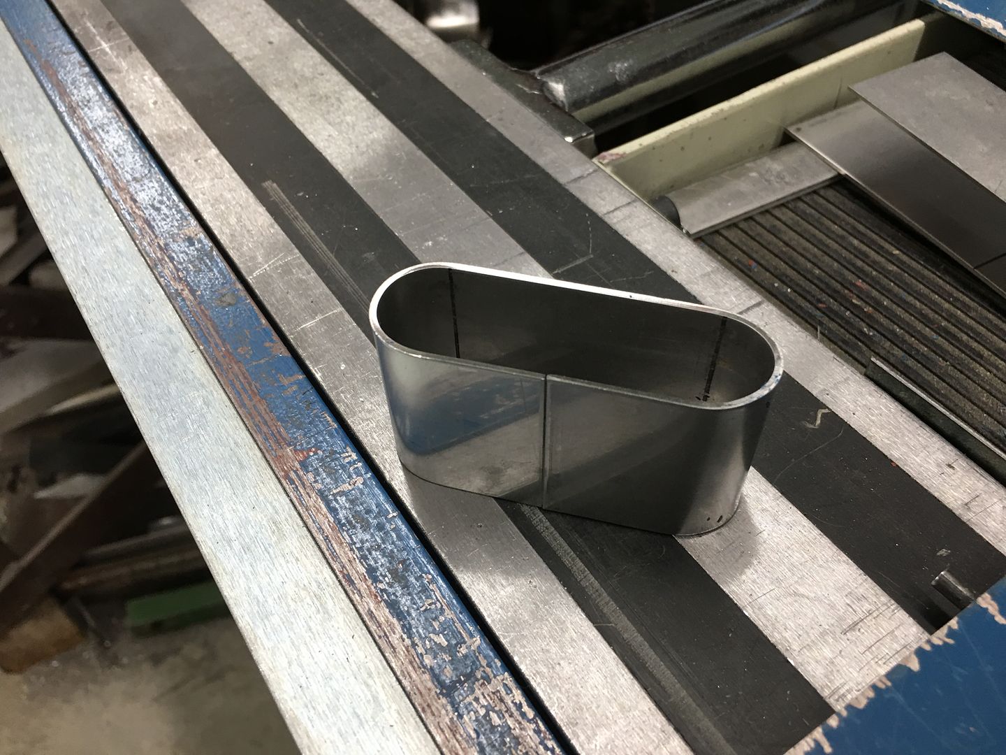
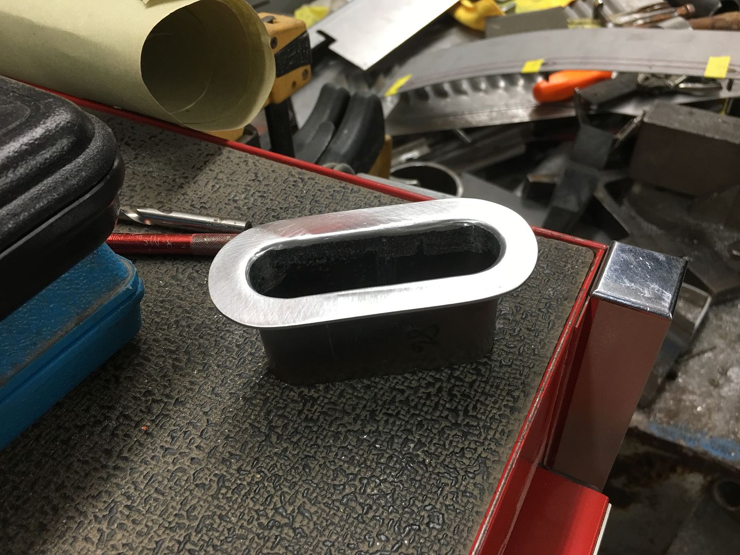
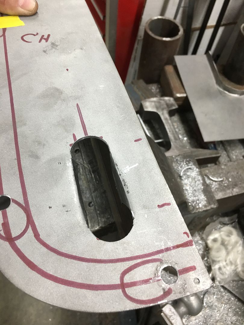
Here's the last detail for the console, we still need our latching mechanism. To keep a minimalist approach, we're going to flush recess some rare earth magnets in the lid, so here's our "pockets" that will be welded into the lid. Starting with some .065 wall tubing the end was faced on the lathe, and the end plates turned to a welding diameter of slightly undersized than the tubing, which allows for a good fusion weld.
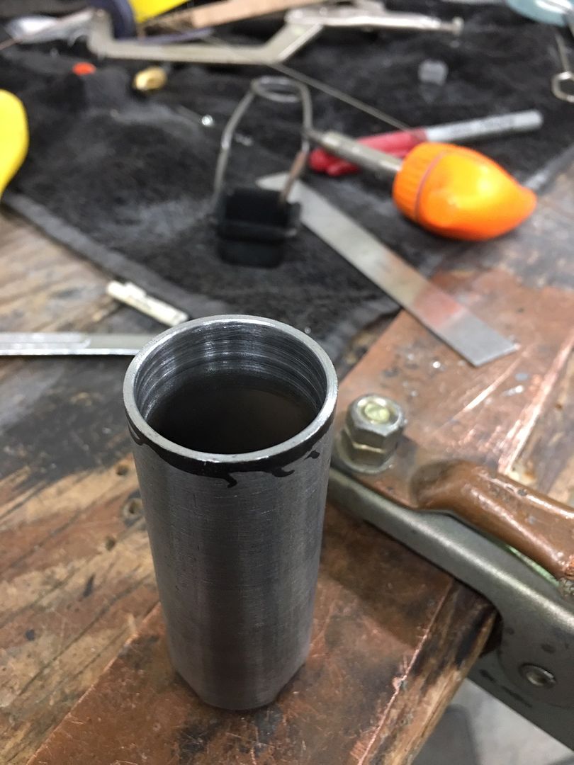
Tacked:
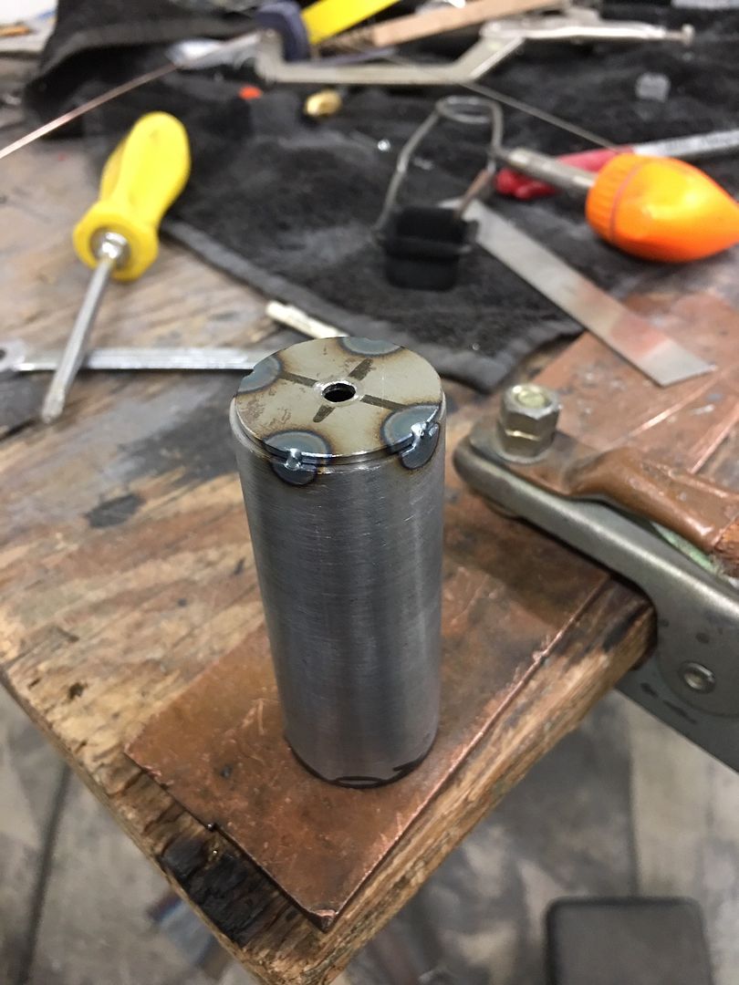
Fusion welded using the TIG:
10-32 hex nut for magnet attachment is tacked on....
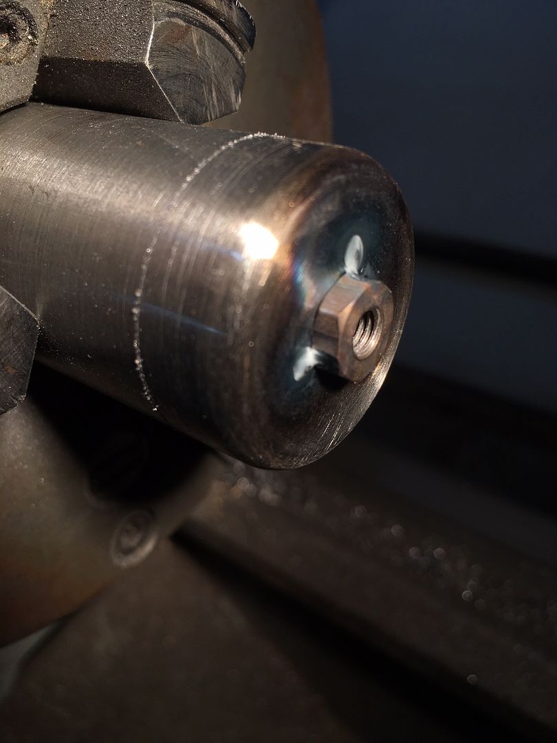
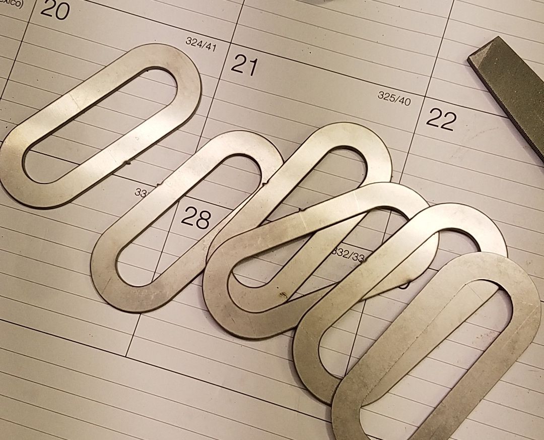
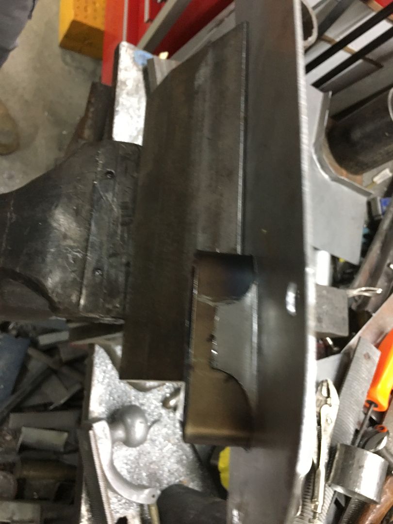
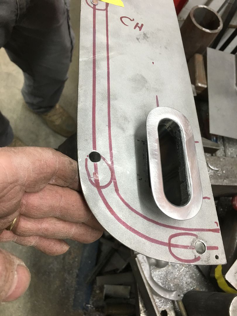
Trimmed to size...
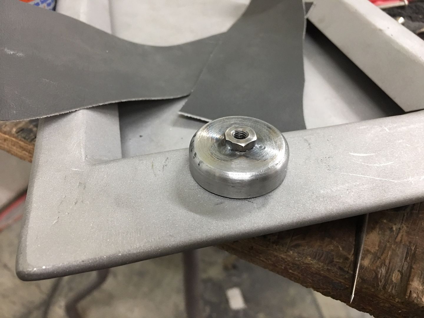
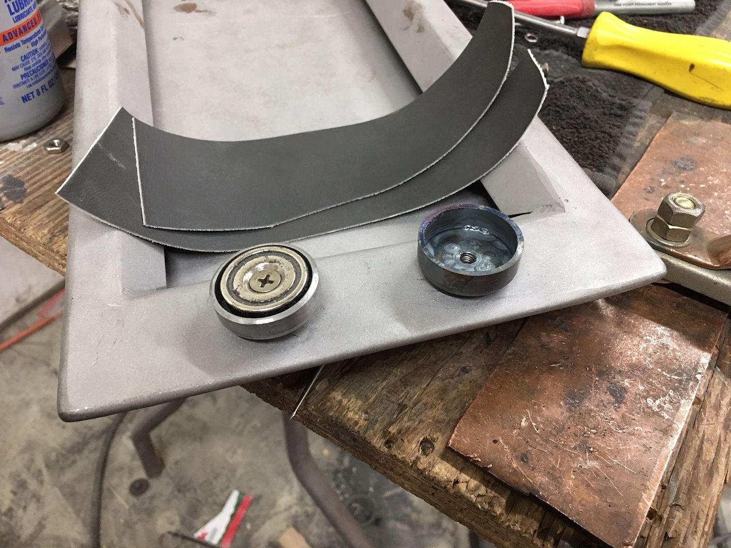
The material scraps shown were to simulate what will be covering the console and lid for the "pull test". Three magnets appeared to work too well, so we are going drill holes and weld in our recess pockets to use two magnets but leave a space in the center for a third, just in case... Once welded and fitted we'll do one more pull test just to make sure the third one isn't needed..
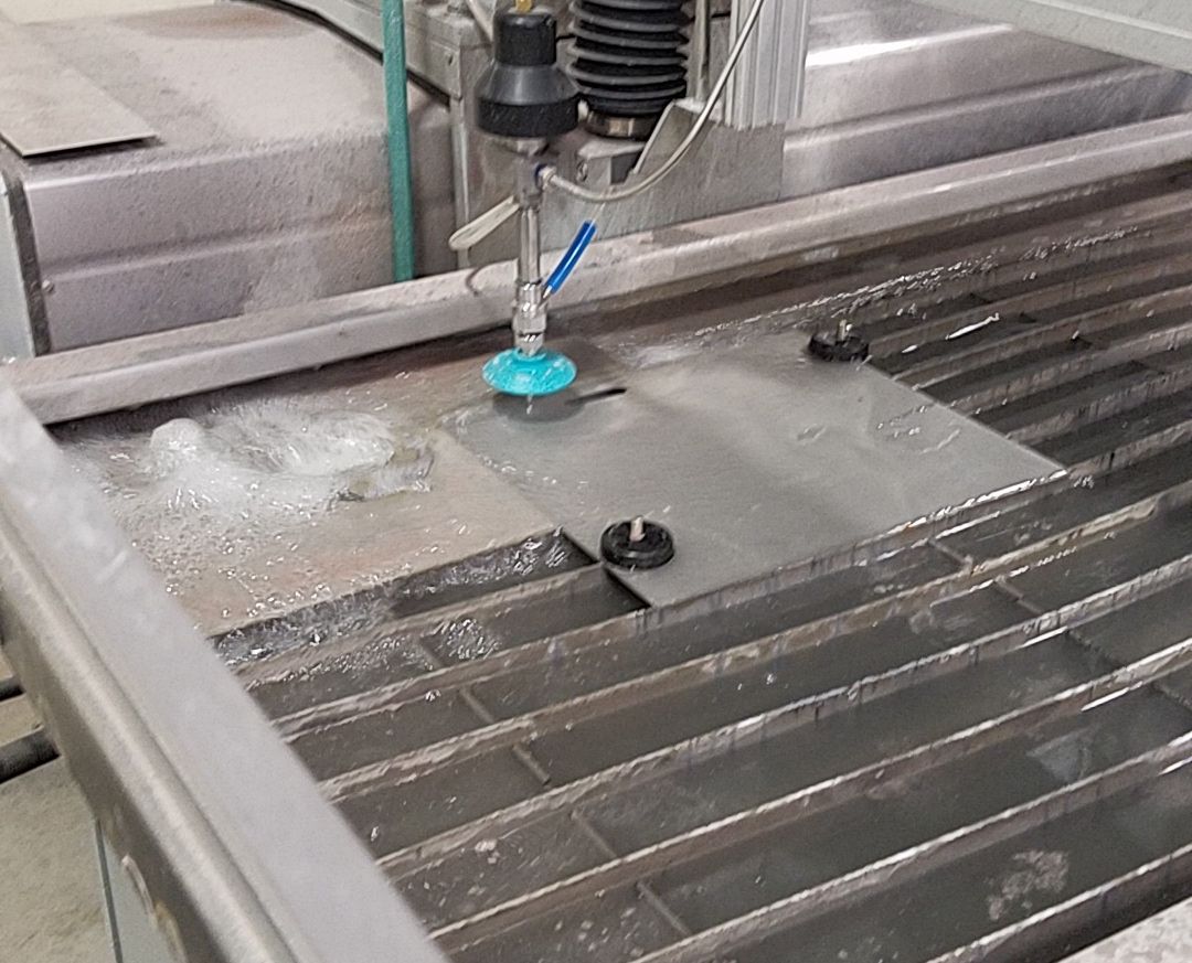
We also had some parts water jetted out of stainless for our seat belt escutcheons, this should help us get better consistency between parts.....and save time..
Some wagon updates, we've been tying up loose ends to get parts ready for upholstery and the roof ready for paint. With the arm rest details ironed out, E is unbolting the kick panels so we can cut out the speaker holes. Mike is getting the roof skin blocked out..
Here's the last detail for the console, we still need our latching mechanism. To keep a minimalist approach, we're going to flush recess some rare earth magnets in the lid, so here's our "pockets" that will be welded into the lid. Starting with some .065 wall tubing the end was faced on the lathe, and the end plates turned to a welding diameter of slightly undersized than the tubing, which allows for a good fusion weld.
Tacked:
Fusion welded using the TIG:
10-32 hex nut for magnet attachment is tacked on....
Trimmed to size...
The material scraps shown were to simulate what will be covering the console and lid for the "pull test". Three magnets appeared to work too well, so we are going drill holes and weld in our recess pockets to use two magnets but leave a space in the center for a third, just in case... Once welded and fitted we'll do one more pull test just to make sure the third one isn't needed..
We also had some parts water jetted out of stainless for our seat belt escutcheons, this should help us get better consistency between parts.....and save time..
Last edited:
WoodsTruck
Well-known member
- Joined
- Jan 12, 2013
- Messages
- 1,029
Love the progress.
Any thoughts on including LED interior lighting? My wife drives a newer Explorer and the dim LED lights around the floor and doors are enough to see things but not enough to distract the driver.
Any thoughts on including LED interior lighting? My wife drives a newer Explorer and the dim LED lights around the floor and doors are enough to see things but not enough to distract the driver.
My wife has those LED lights in her vehicle as well, they are a nice touch. Will have to see what the owner says...
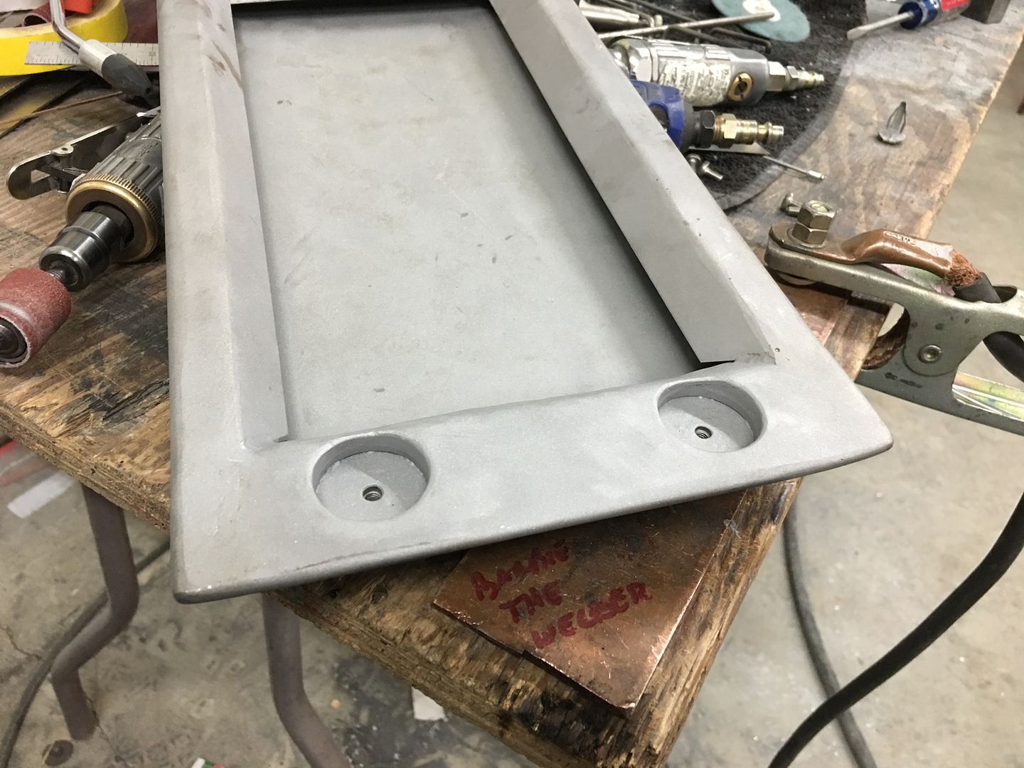
We got the holes added in the console lid for the pocket recesses.....
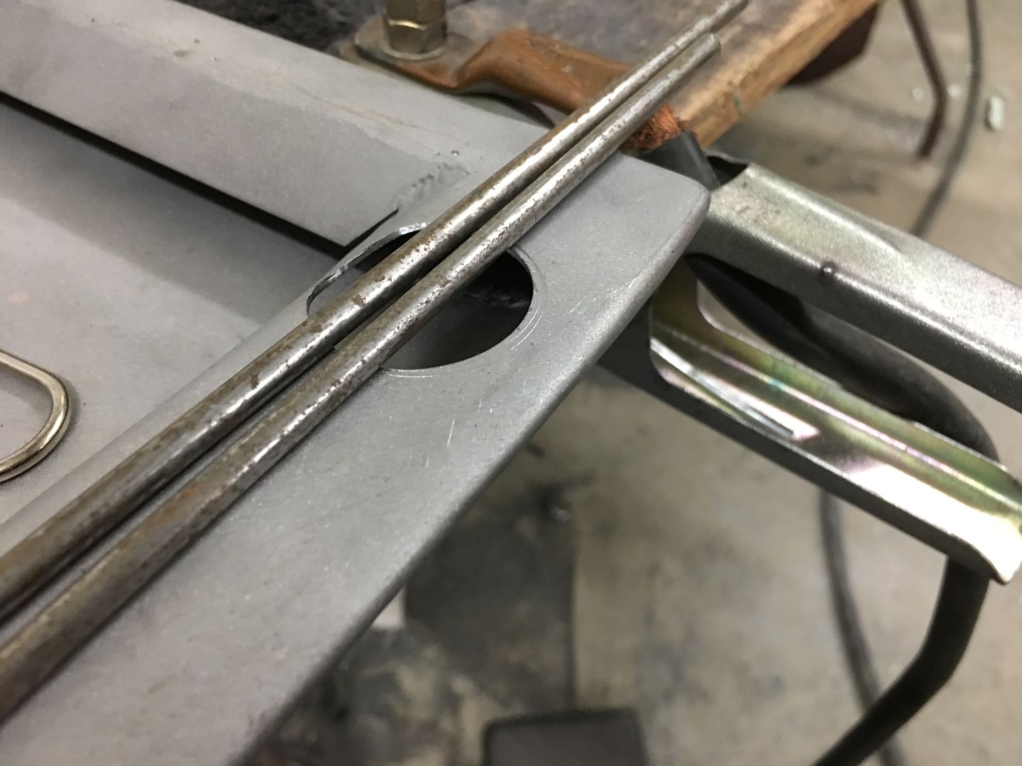
A bent fender washer and 3/16 rods serve to hold the pockets in place while tacked in with the TIG....
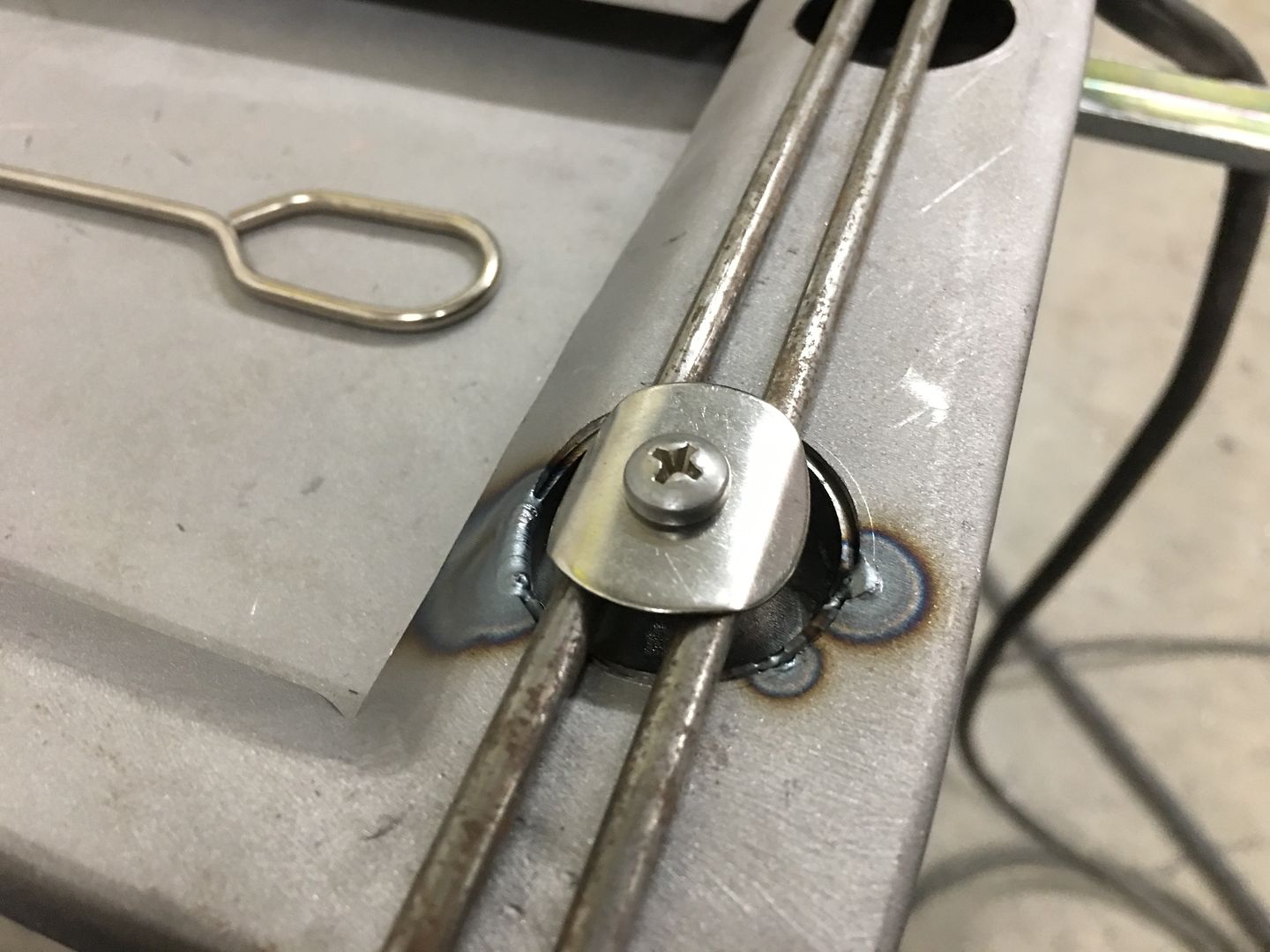
Test fit of the magnets...
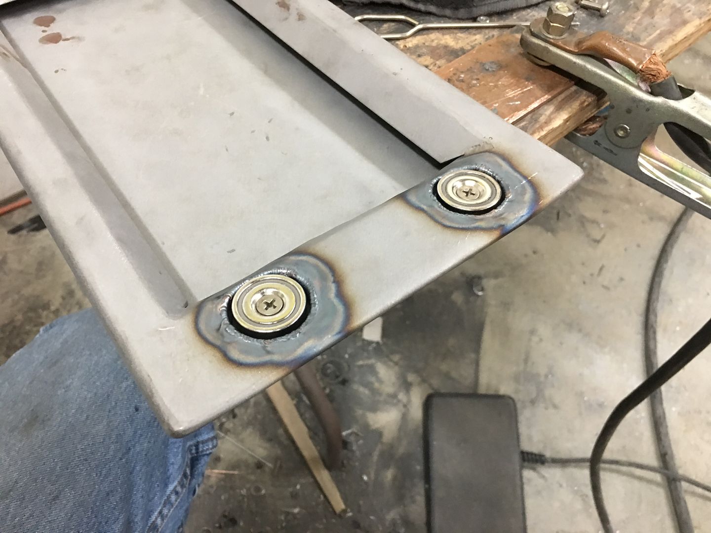
Video of the console lid, testing the magnet pull for our latching method..
.
We got the holes added in the console lid for the pocket recesses.....
A bent fender washer and 3/16 rods serve to hold the pockets in place while tacked in with the TIG....
Test fit of the magnets...
Video of the console lid, testing the magnet pull for our latching method..
.
Last edited:
gofastwclass
Well-known member
Custom metal console that looks like it almost could have been factory, the nearly hidden hinges, the hidden magnets for a latching system. Looks like the perfect solution for a really subtle custom vehicle.
shortykorte
Well-known member
Looking good. Attention to detail is top par. How many would think to include scraps of material when testing magnets.
One lesson learned here, I put into action. I don’t have a brake so I used my little vise brake to score the bend line so I could bend more precisely. Thanks.
Sent from my iPhone using The Garage Journal mobile app
One lesson learned here, I put into action. I don’t have a brake so I used my little vise brake to score the bend line so I could bend more precisely. Thanks.
Sent from my iPhone using The Garage Journal mobile app
Attachments

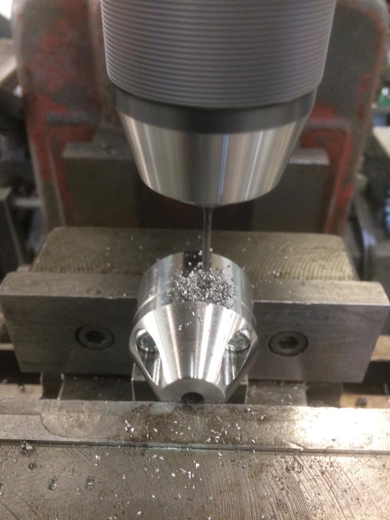
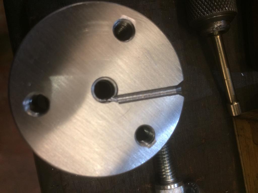
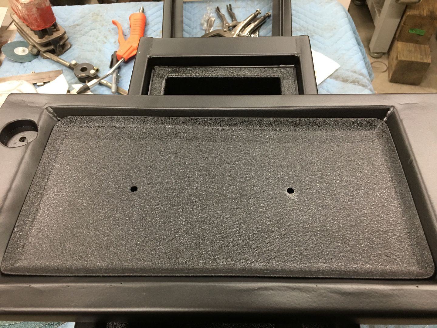
Dotting the i's, crossing the t's... The insert for the bottom side of the console lid will be held in with a couple of 10-32 screws into a rivet nut. To insure the rivet nut is flush on the outside for the installation of upholstery, we want to provide a slight recess for the rivet nut flange. Here's the punch and die we made for the occasion, the bottom die is machined on the side to keep things from moving when clamped in the vise.
South Bend milling machine:
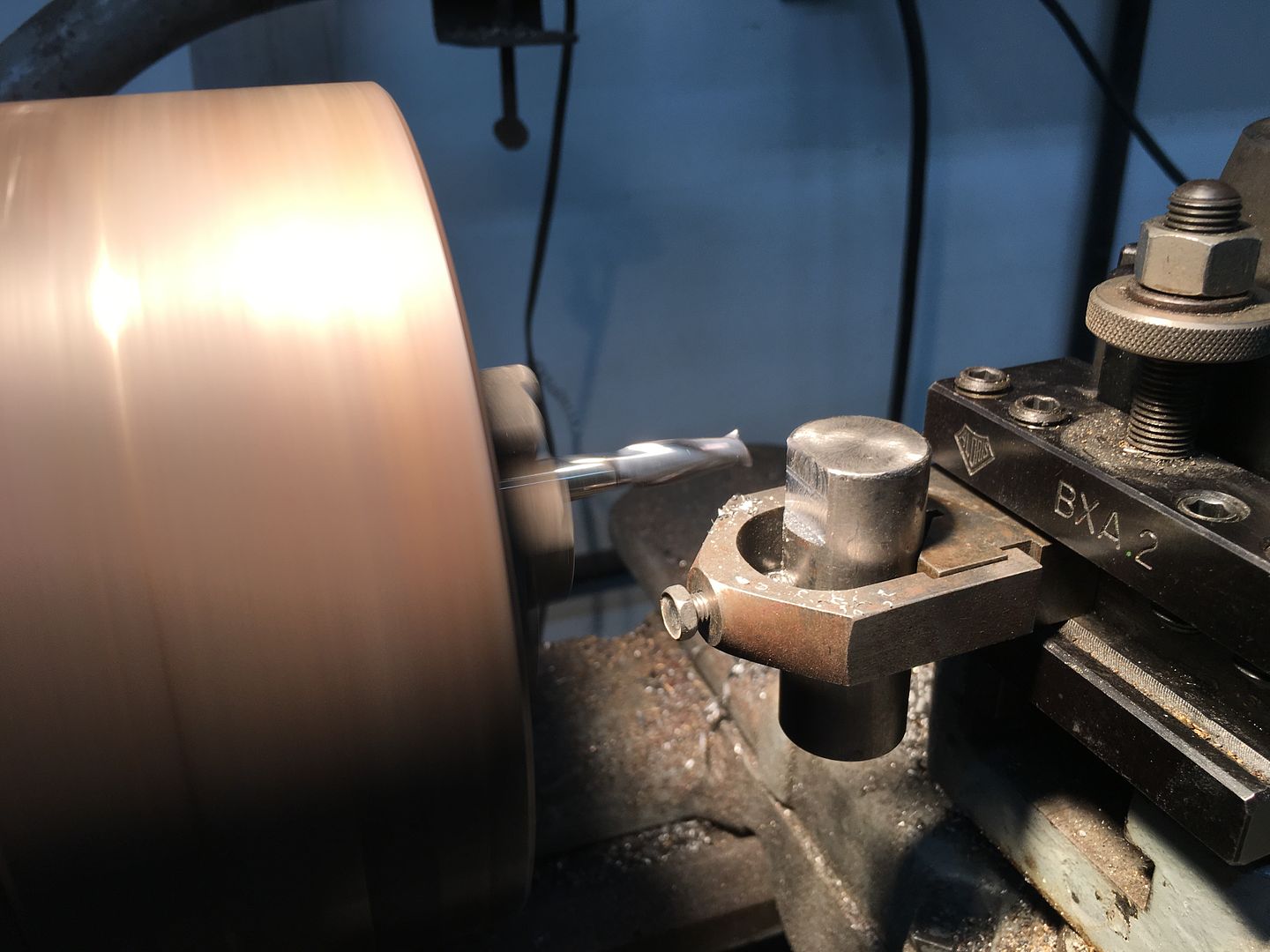
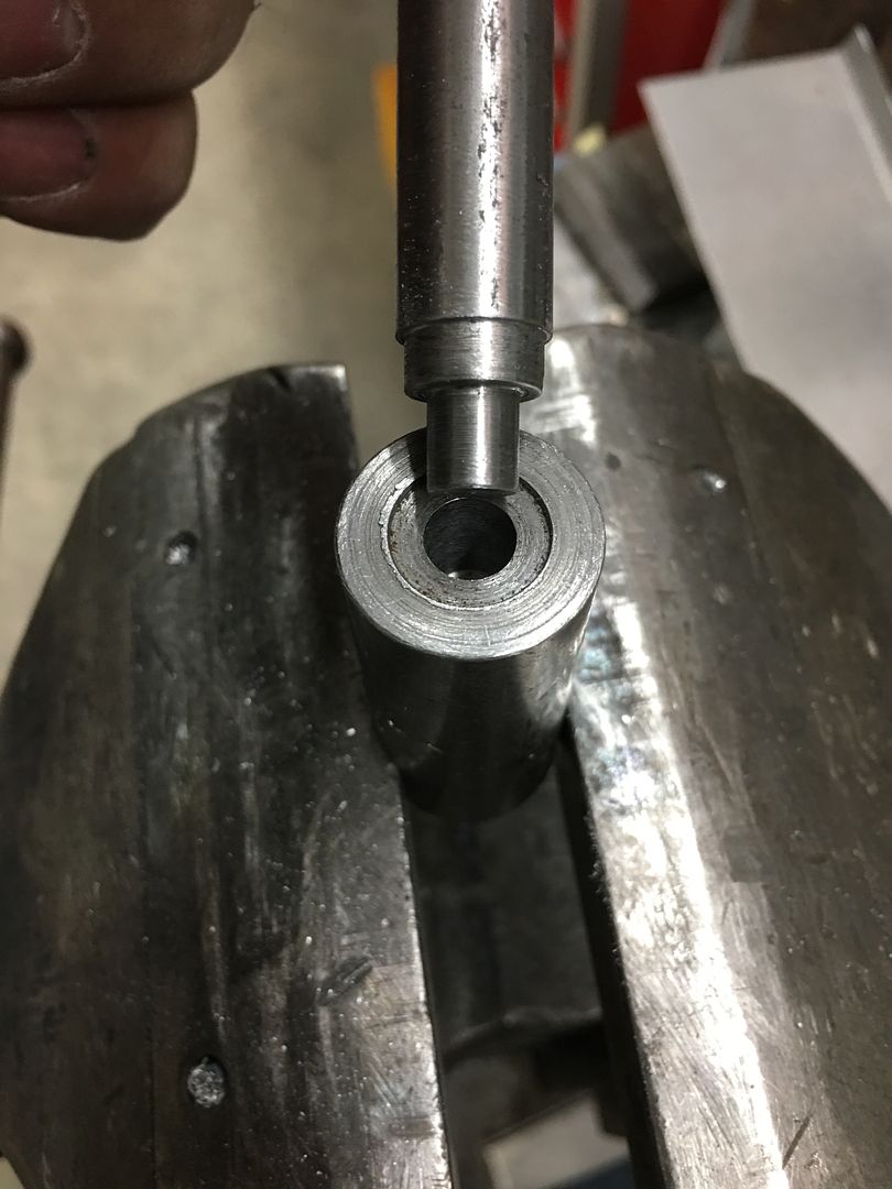
action shot:
inner parts installed...
ready for powder coat / epoxy primer, whichever comes first...
South Bend milling machine:
action shot:
inner parts installed...
ready for powder coat / epoxy primer, whichever comes first...
larry4406
Well-known member
Nicely done!
Boosted1
Well-known member
Wow! That console is a work of art.
quietsailor
Active member
Thanks Guys!
We were originally going to hinge the console lid along the passenger side, but thought it would be better accessible from either front seat if it was hinged at the rear. We're using the same hinge as we used for the widened glove box door. In our attempt to add a torsion spring to keep the lid upright in the open position, we couldn't find the size to fit our 1/8" diameter hinge pin with enough torsion to hold the lid open. (Yes, even McMaster failed us) So we decided to wrap our own.
I'm just caching up on this thread after it got out of my bookmarks page somehow
. Thank you for going to so much trouble to explain what you do, this thread is more educational than a lot of courses I have attended and paid for!! 
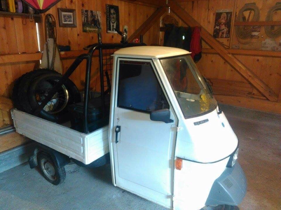
I also follow a UK forum called RetroRides and there is a mad scientist/engineer type on there called JohnnyBravo. Recently he had to create a heater coil for a kiln and designed tools to use in the lathe to wrap wire. The post he wrote up is here and the thread itself is here if anyone wants to read from the start: There be three wheels on my wagon all about restoring a three wheel pickup
Some of the wire wrapping tools are;
and
but it's better to read the actual thread JB explains it really well
TimeWarpF100
Well-known member
Dotting the i's, crossing the t's... The insert for the bottom side of the console lid will be held in with a couple of 10-32 screws into a rivet nut. To insure the rivet nut is flush on the outside for the installation of upholstery, we want to provide a slight recess for the rivet nut flange. Here's the punch and die we made for the occasion, the bottom die is machined on the side to keep things from moving when clamped in the vise.
South Bend milling machine:
action shot:
inner parts installed...
ready for powder coat / epoxy primer, whichever comes first...
Fantastic as usual! I hope you plan of stitching all these photo's together to make a YouTube video or 2! It would be a great watch. Even .5 seconds per photo.
TimeWarpF100
Well-known member
This thread, while it may show quite a bit of work on vehicles that come in the shop, is primarily going to focus on providing metalworking/metal shaping tutorials, where ever possible using simple hand tools, in hopes that it may inspire others to learn the craft. While I am no expert, in many cases learning as I go, feedback and suggestions from others is more than welcome. Where I strive to improve methods with each lessons learned, outside suggestion is often the source to provoke such thought and vision. Many times this "re-thinking the process" comes via someone questioning that process shown, so feel free to ask away!
I've been travelling quite a bit for the day job all this past fall, which has put a cramp in time available in the shop, but that has subsided a bit so now is as good a time as any to start a shop thread..
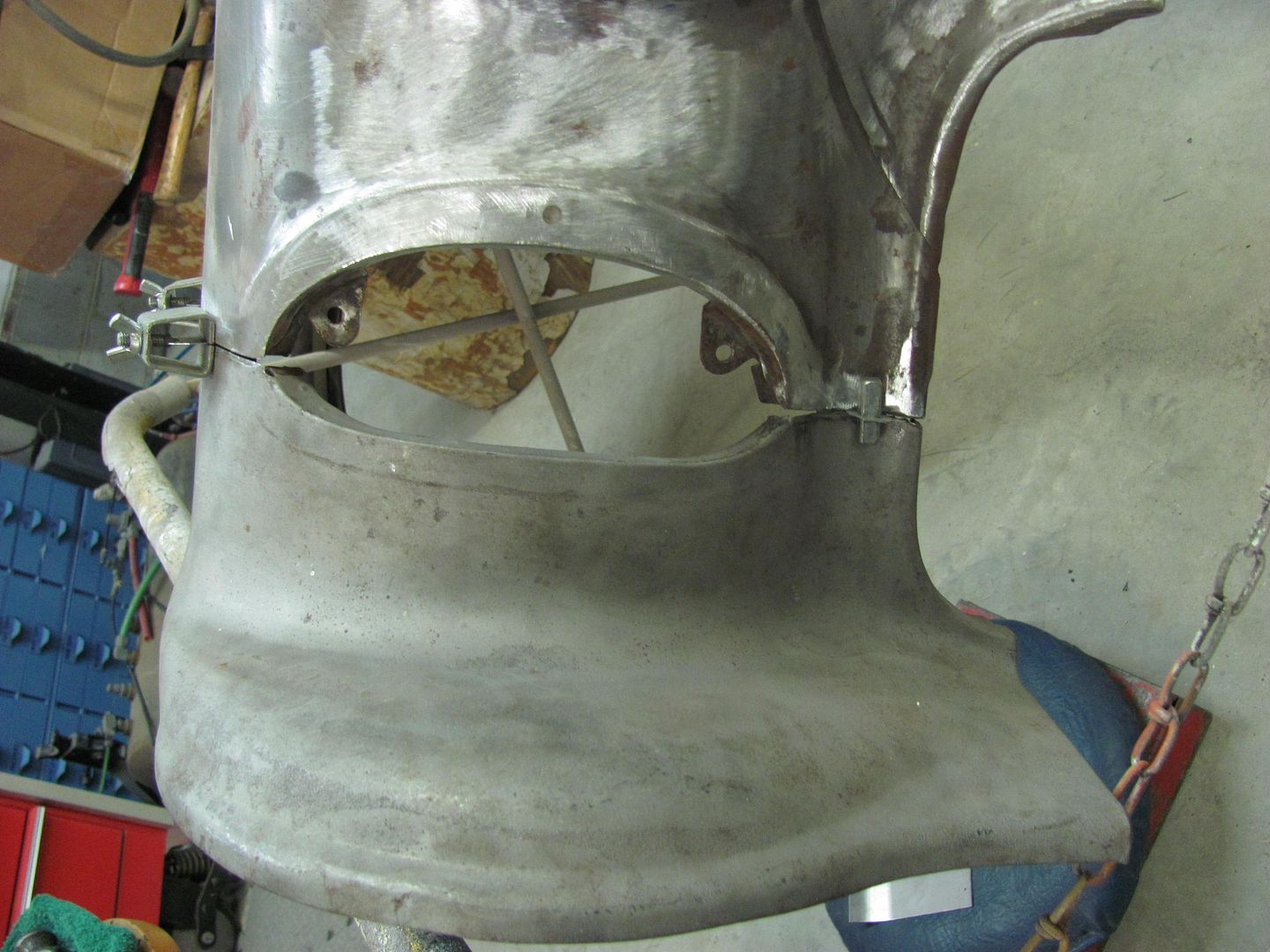
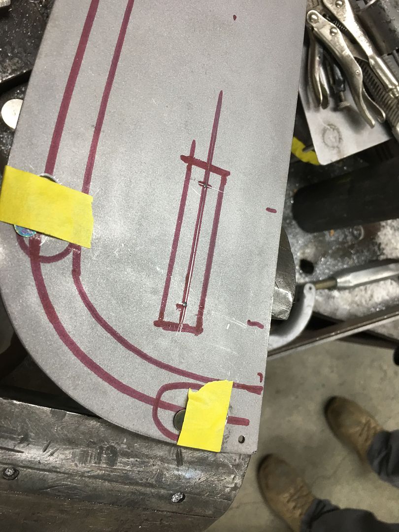
This is a customer car, the owner and I discussed shaving the fender seams quite a while back, and she asked about it again last week, so I guess we're on the hook..
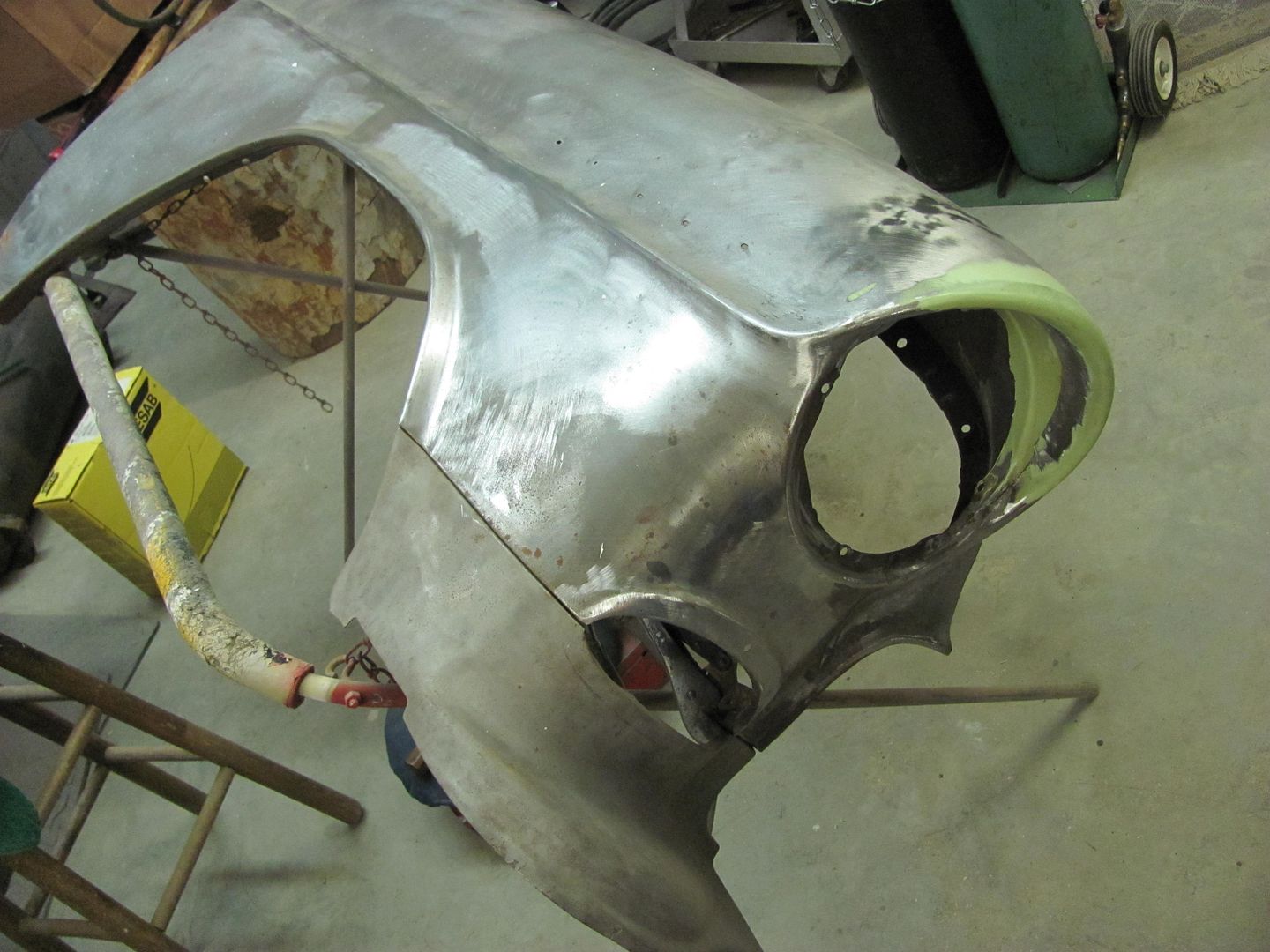
The bolting plates are cut out of the way, and the folded flange is trimmed, leaving a bit of extra to allow for fine tuning the weld joint.
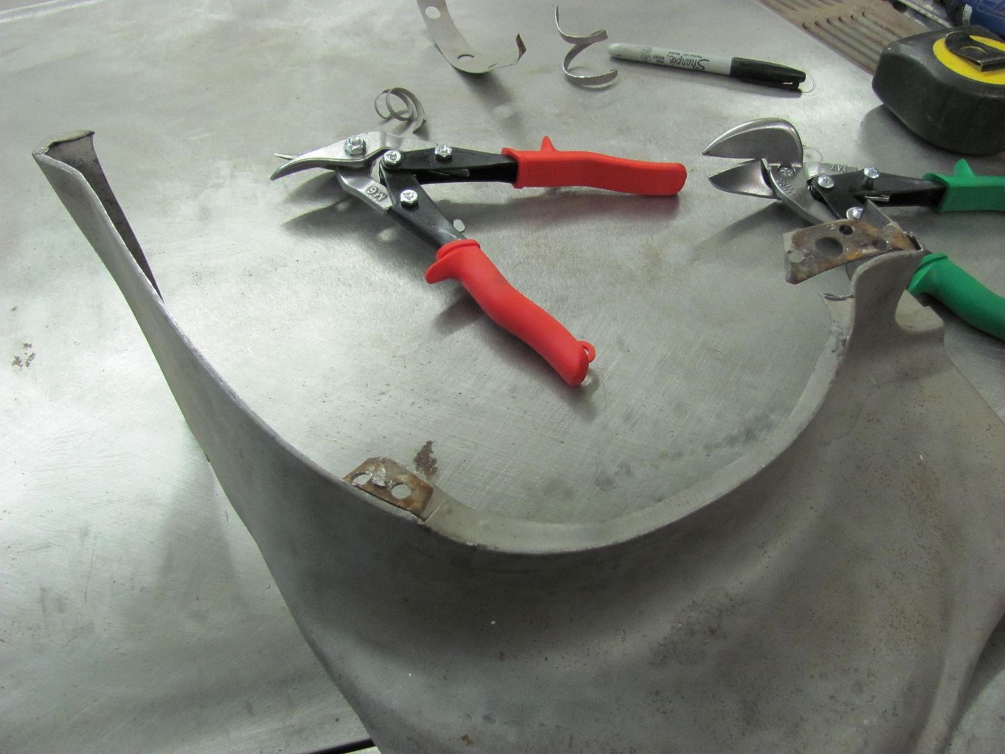
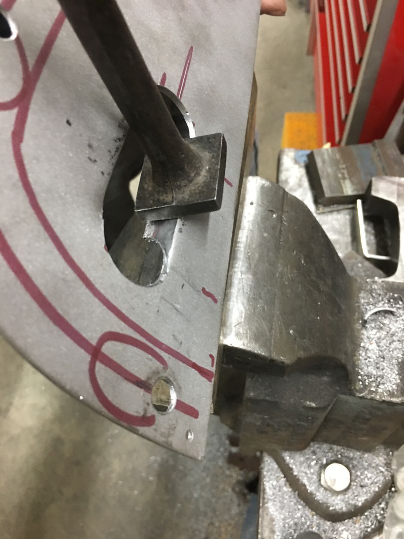
Bottom of the fender is cut loose from the bolting plate using the cutoff wheel. Then sanding the face of the fender leaves a contrast at the bend of the flange for a good guide for trimming with snips....
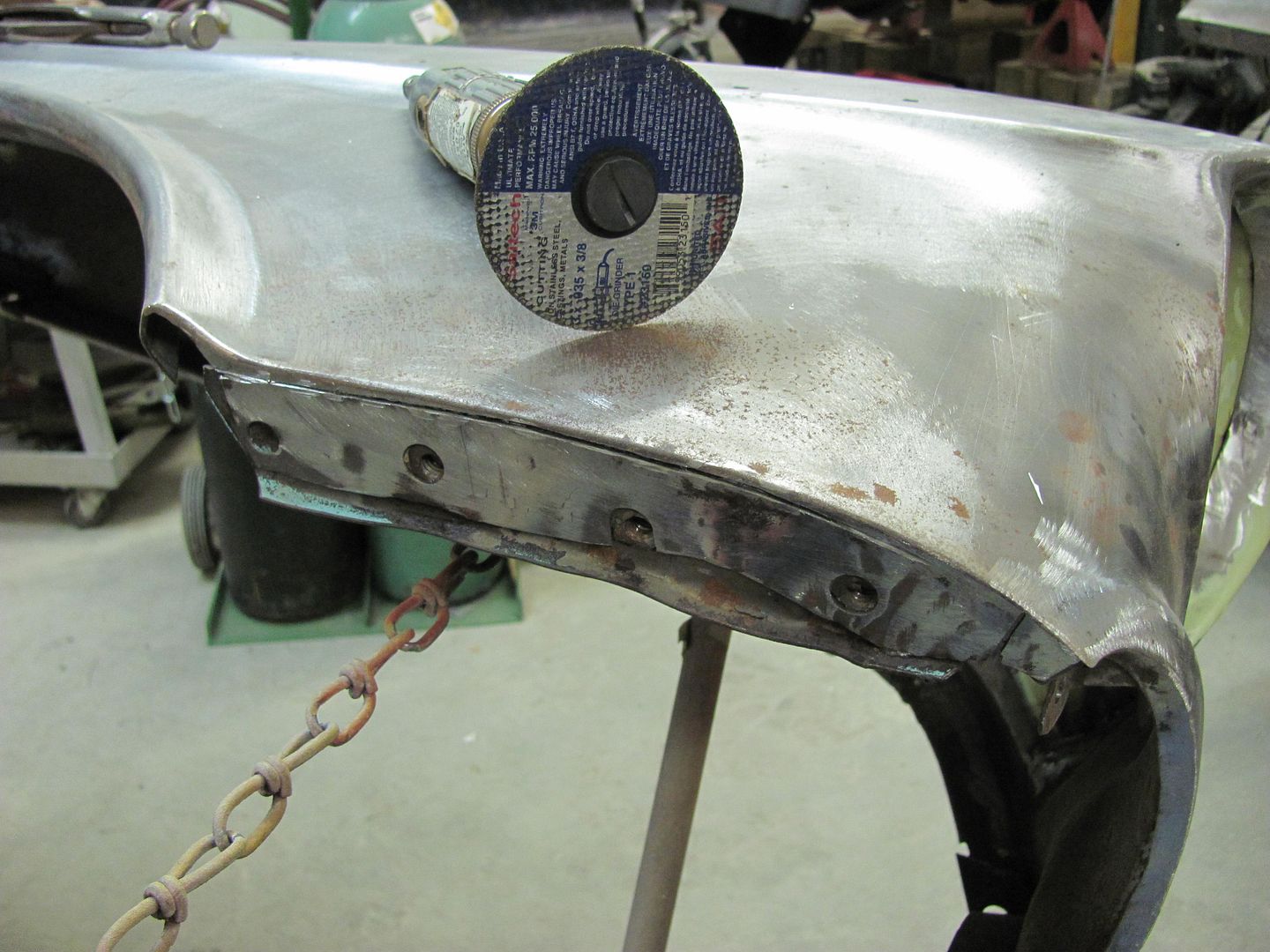
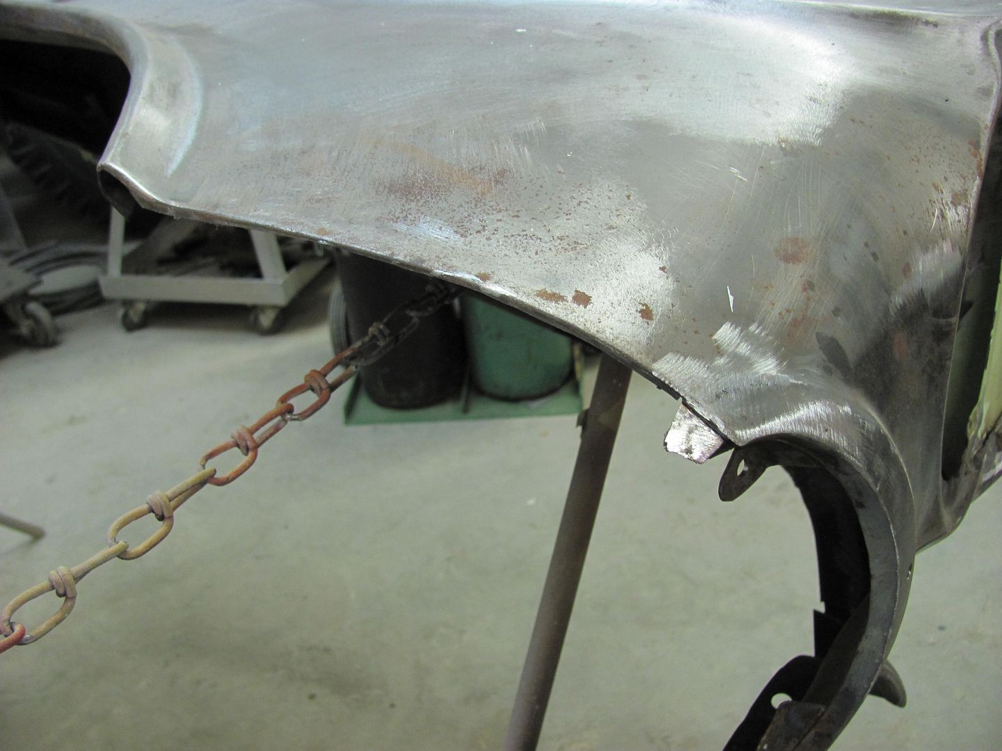
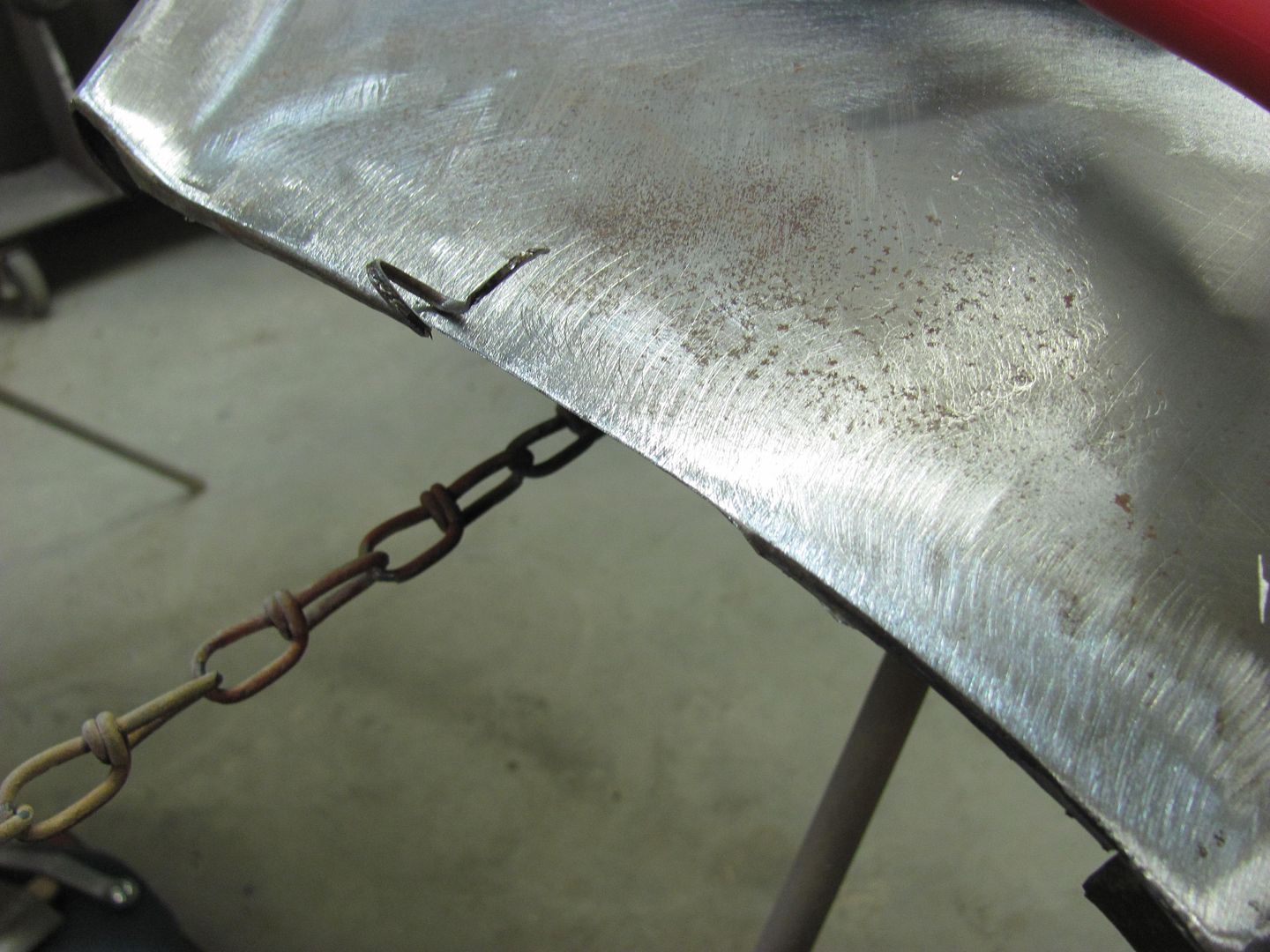
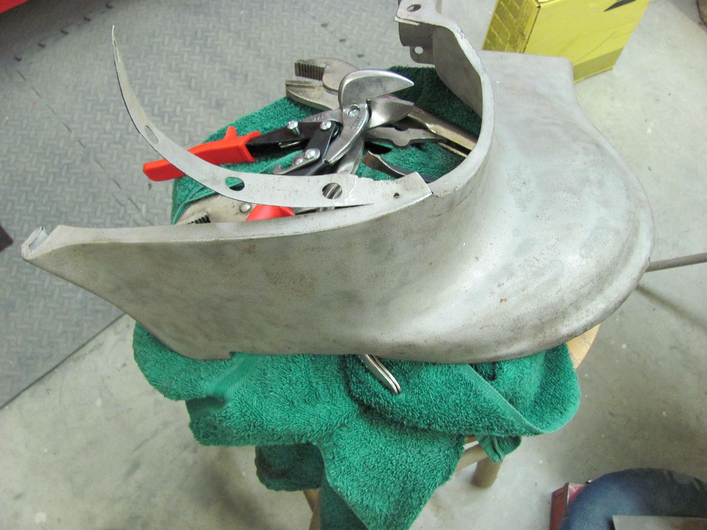
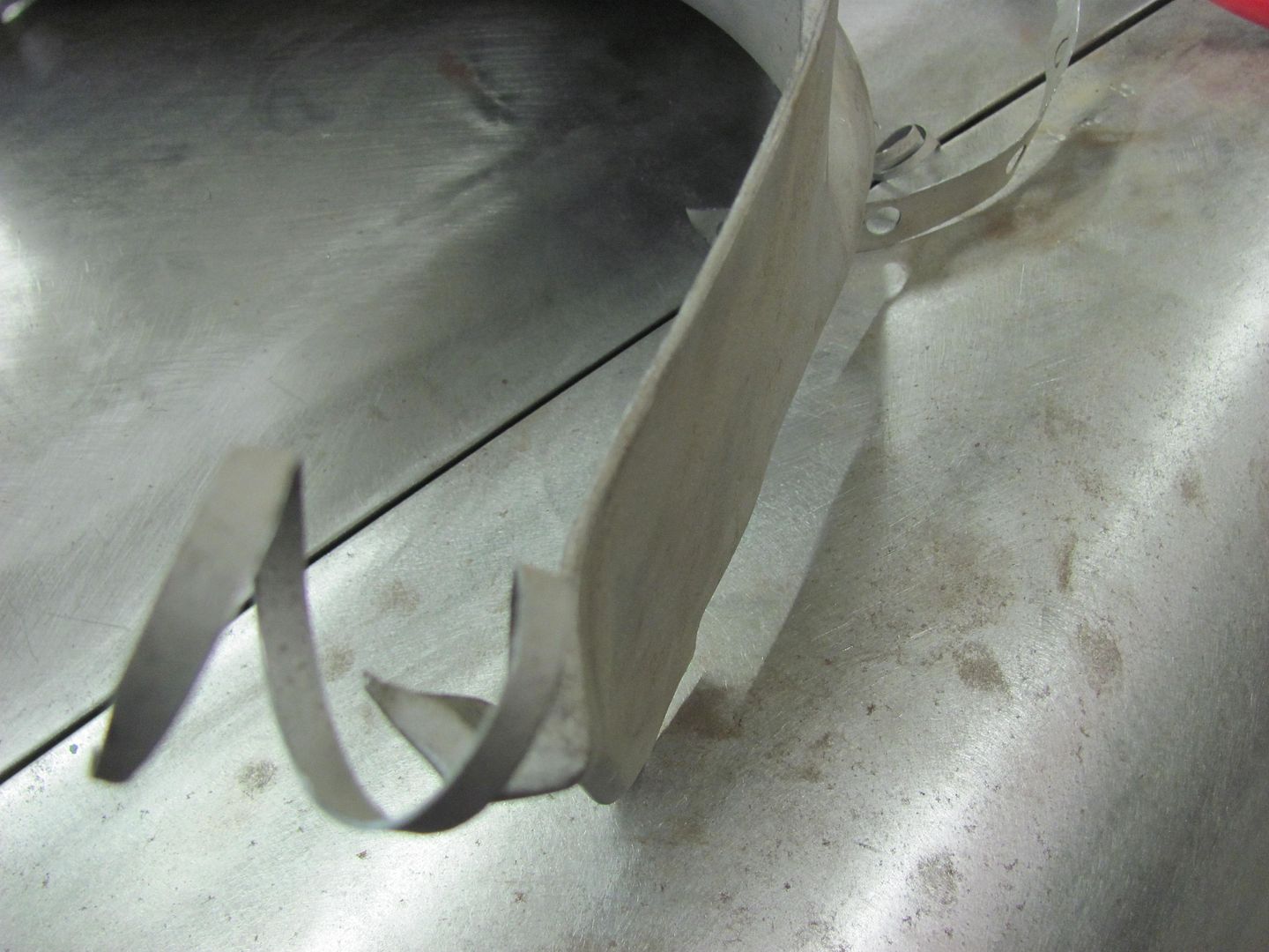
Planishing out the fold to fill the gap....
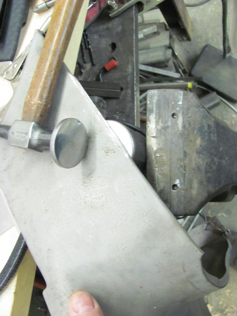
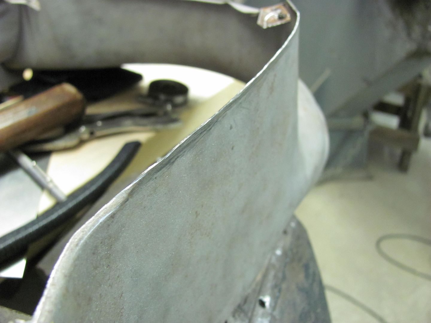
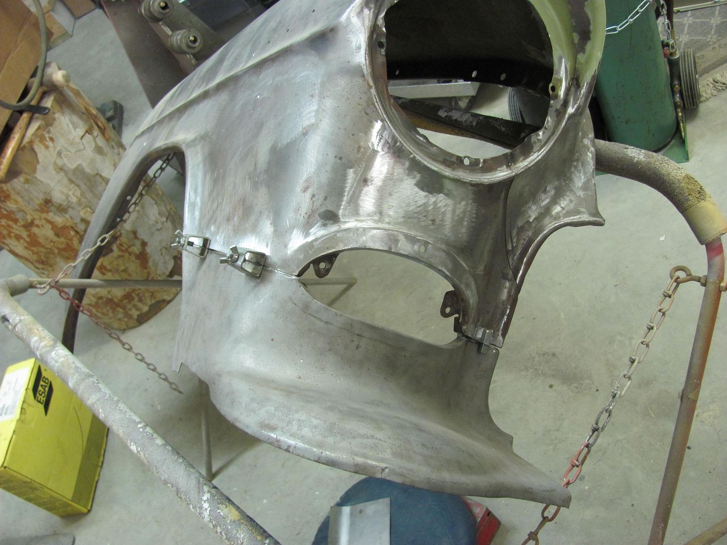
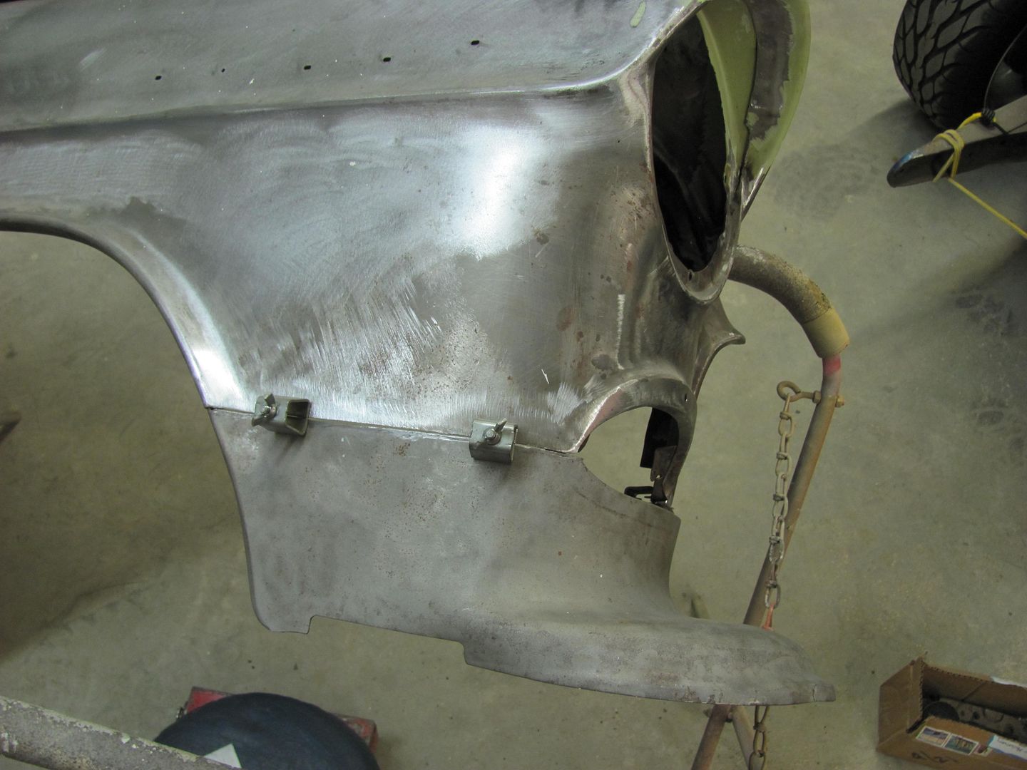
Clamps used to test fit. Still needs some fine tuning for zero gaps, but we'll finish that another day..
I was guessing it was a "few" years since this thread started. Looking back its only one day short of 6 years!
It does not seem that long ago since I read this first post.
But, I guess its going on 7 yrs since I started my thread.
Been following since that very first post. In this time the '56 BelAir hardtop I was doing is on the road but still needs its final sand n buff. Looking back at photo's of it yesterday the project was started sometime in the fall of 1997.
Have really enjoyed this thread and learned a lot. Just wish I had a fraction of the talent to go with it.
Thanks for the comments guys!
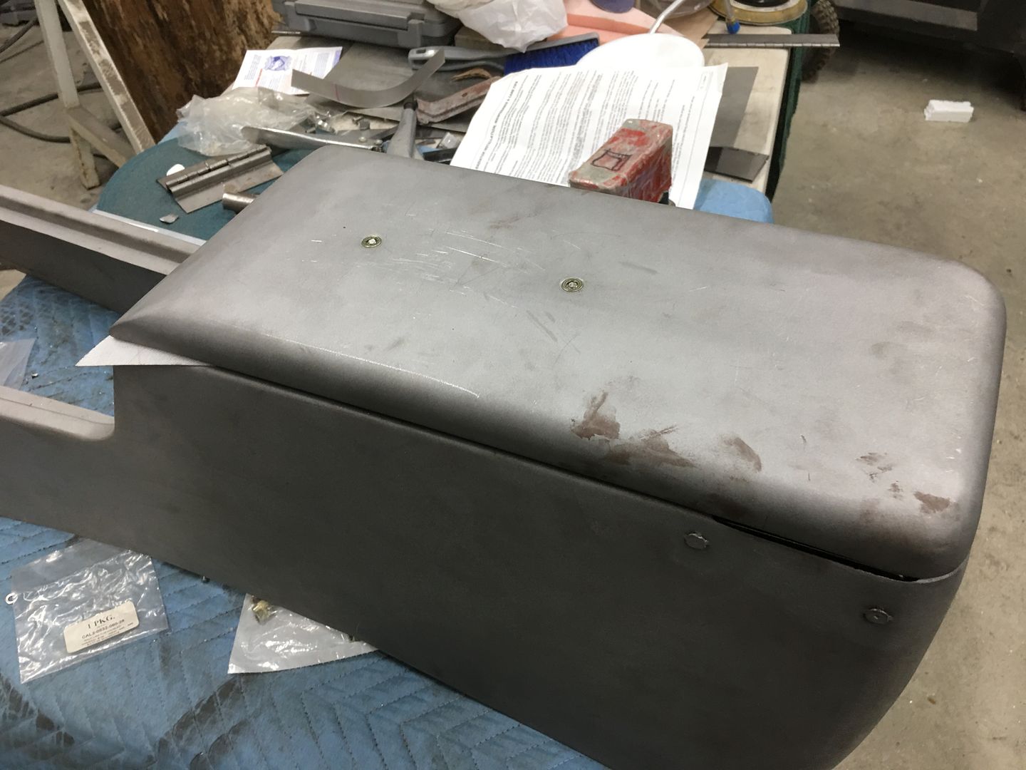
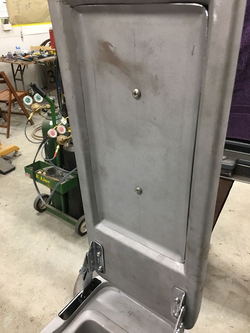
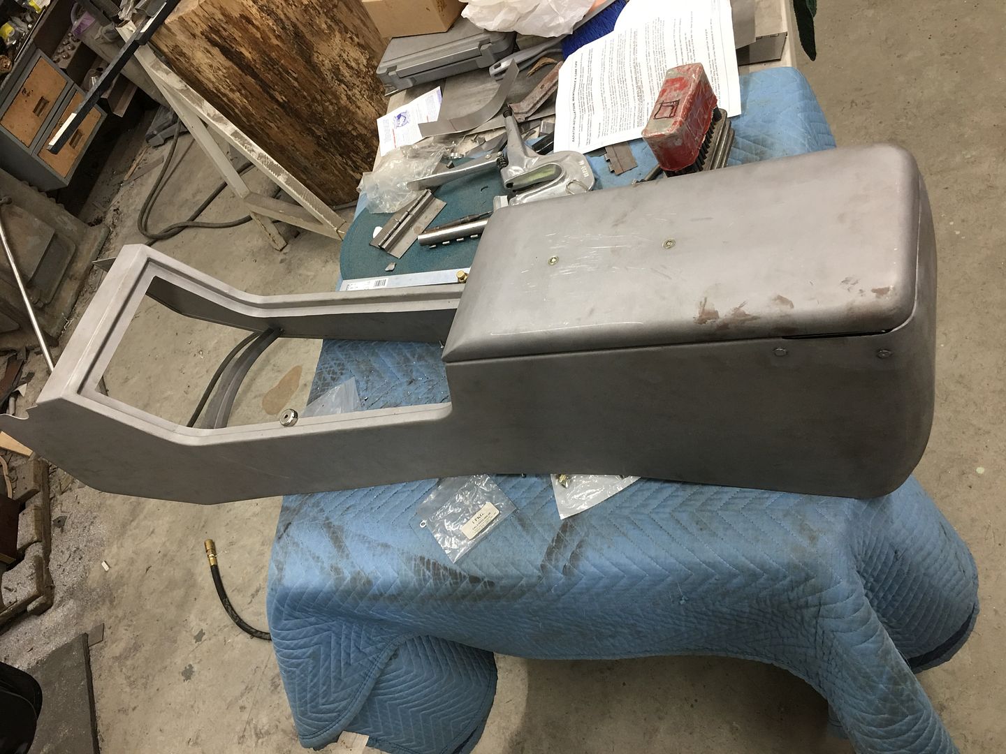
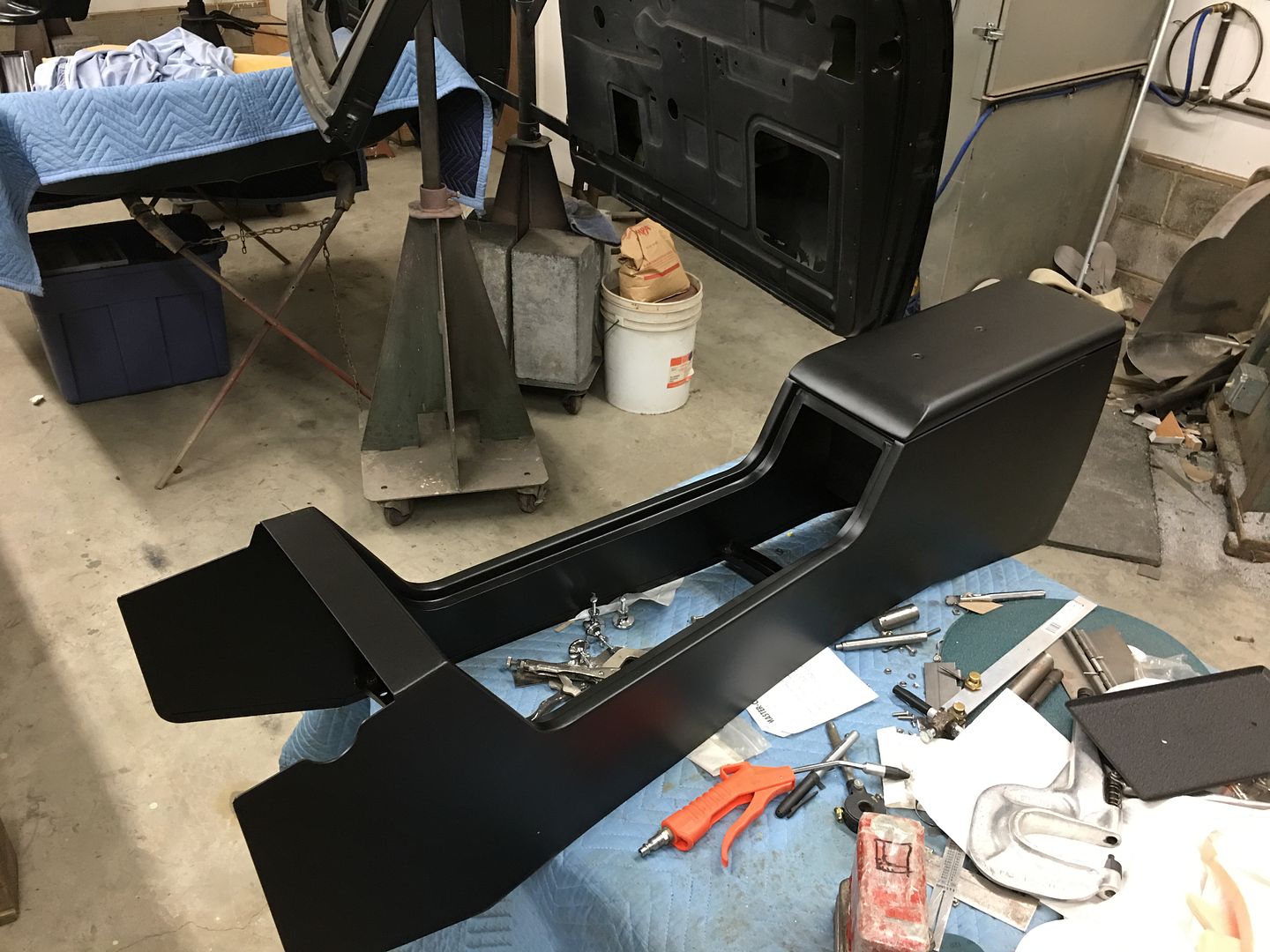
Picked up the console from the powder coater, the outside was done in satin black and will be covered in upholstery, the inside parts were done in wrinkle finish, this will be their "covering"


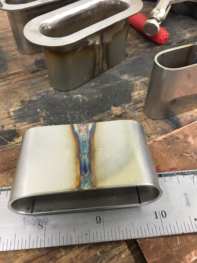
Tonight we worked on some stainless for our seat belt escutcheons..
Some measurements and geometry from high school should get us the correct size from the onset...
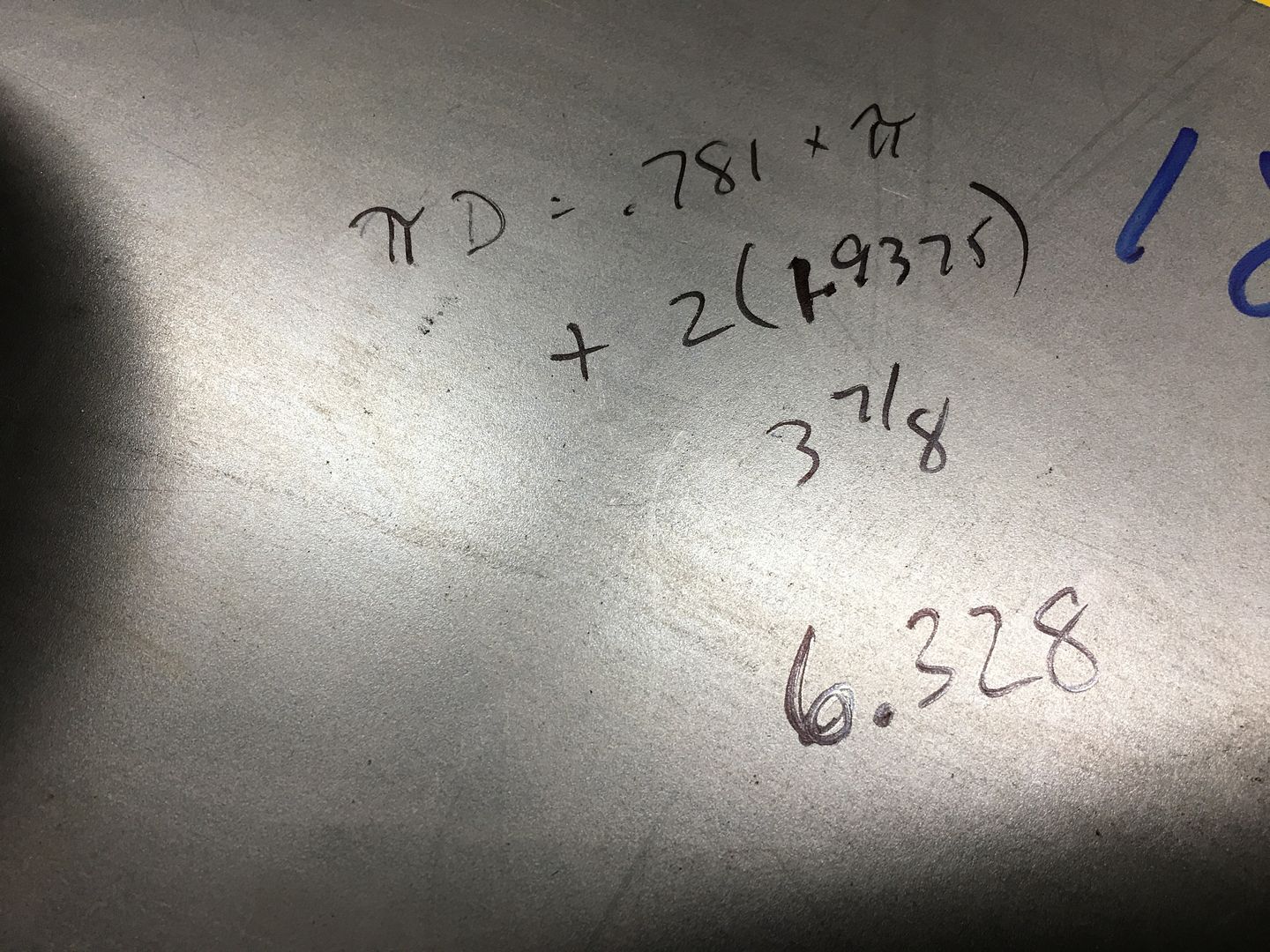
Using the mag brake and a 3/4 tube to bend our radius...
Tacked together using the TIG

Got running late and missed some pictures, but here's the part welded up and polished..
.
Picked up the console from the powder coater, the outside was done in satin black and will be covered in upholstery, the inside parts were done in wrinkle finish, this will be their "covering"
Tonight we worked on some stainless for our seat belt escutcheons..
Some measurements and geometry from high school should get us the correct size from the onset...
Using the mag brake and a 3/4 tube to bend our radius...
Tacked together using the TIG
Got running late and missed some pictures, but here's the part welded up and polished..
.
don long
Well-known member
Robert
I haven't checked in in a while
I sure do like those quick videos they take all the guess work out of learning
Thank You
Don
I haven't checked in in a while
I sure do like those quick videos they take all the guess work out of learning
Thank You
Don
BORING HOP YARD
Well-known member
Robert that console came out sweet, its a shame most of it will be covered.
When you started thinking about the design-build, did you have a vision of the final project in your head at the start or did you design as you went along?
Were you thinking how do I attach it to the body, how tall, how long, how wide, ect.
I'm just trying to understand how a master looks at a project like this.
Are you happy with the result?
Thanks for sharing!
We started with a basic idea and cut some "side panels" out of cardboard and had the owner stop by, sit in the car, tested arm rest height, location of the console back with seats slid forward and backward, width, etc. , and it's kind of just morphed from there into what you see today, details like mounting, etc added as we went... I didn't want to make it out of wood as they look too boxy IMO, and I can't weld it. I know this one is not that far off from boxy, but I think it will complement the interior well.
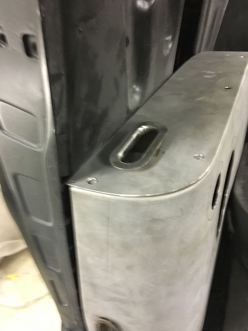
More progress, Mike installed the driver seat so we could mock up the lap belt for locating the lower escutcheon.
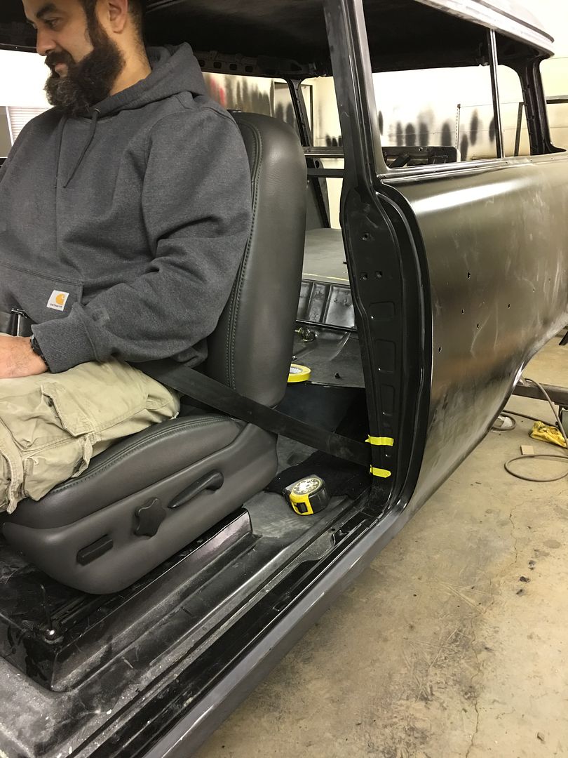
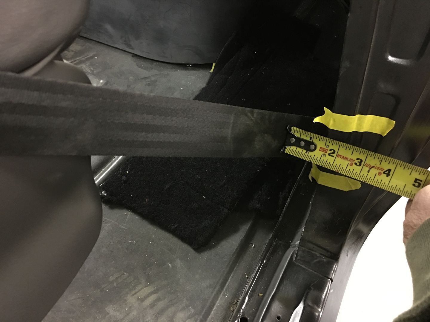
Then we contemplated vertical or parallel....
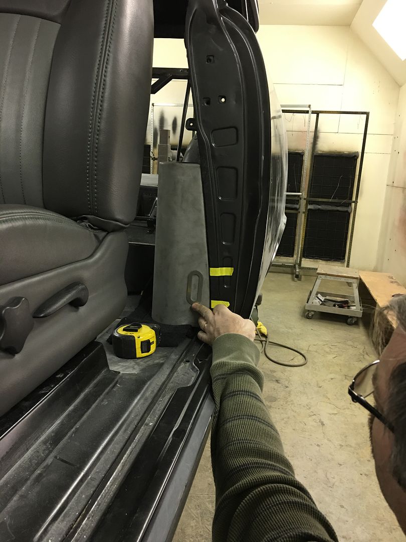
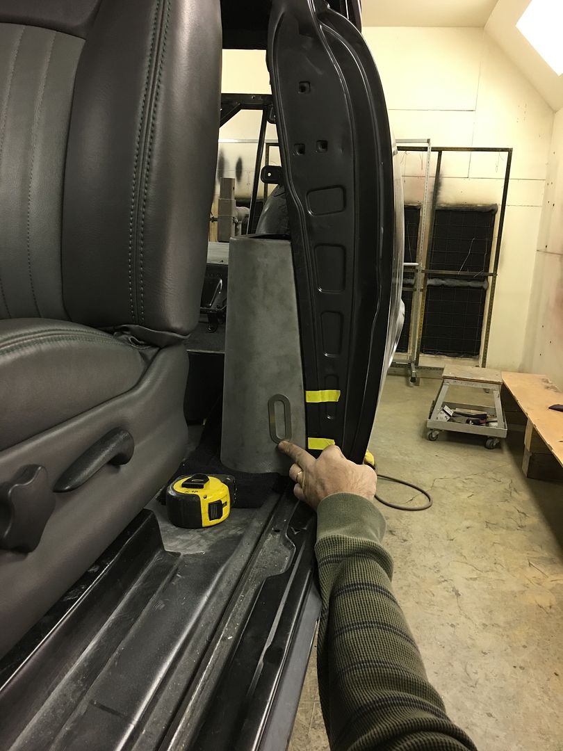
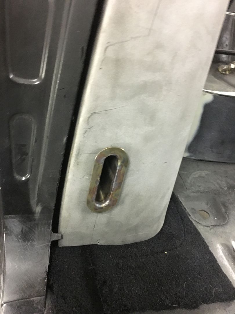
Remaining escutcheons were welded up...
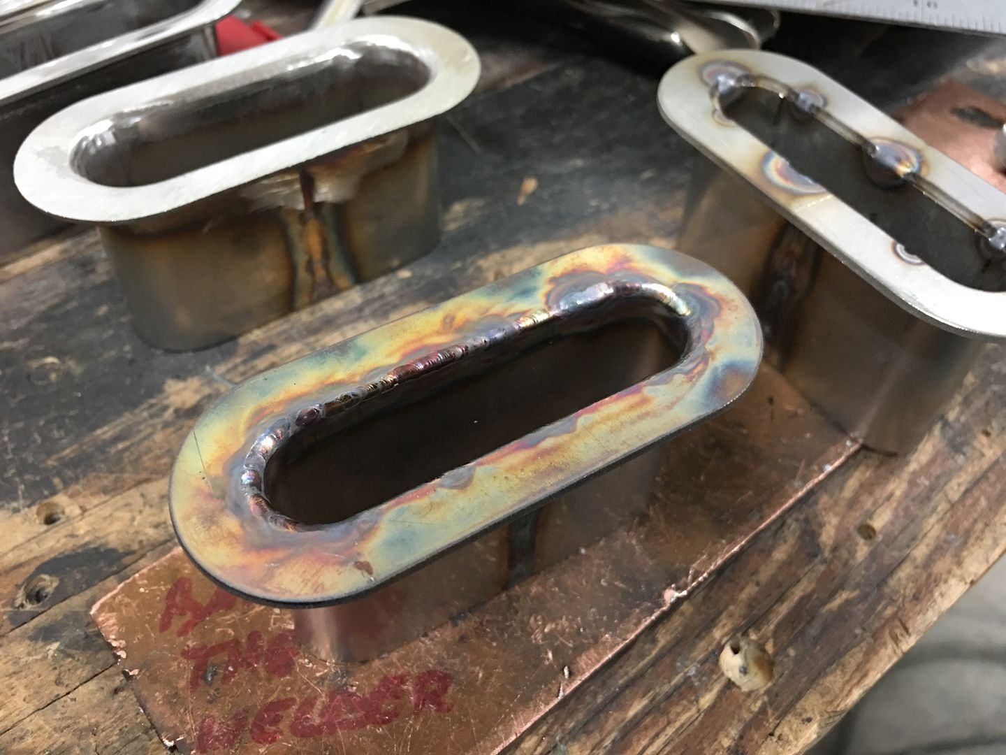
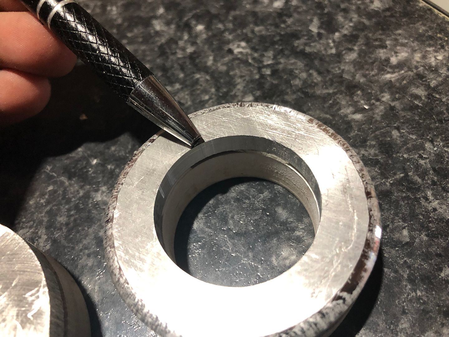
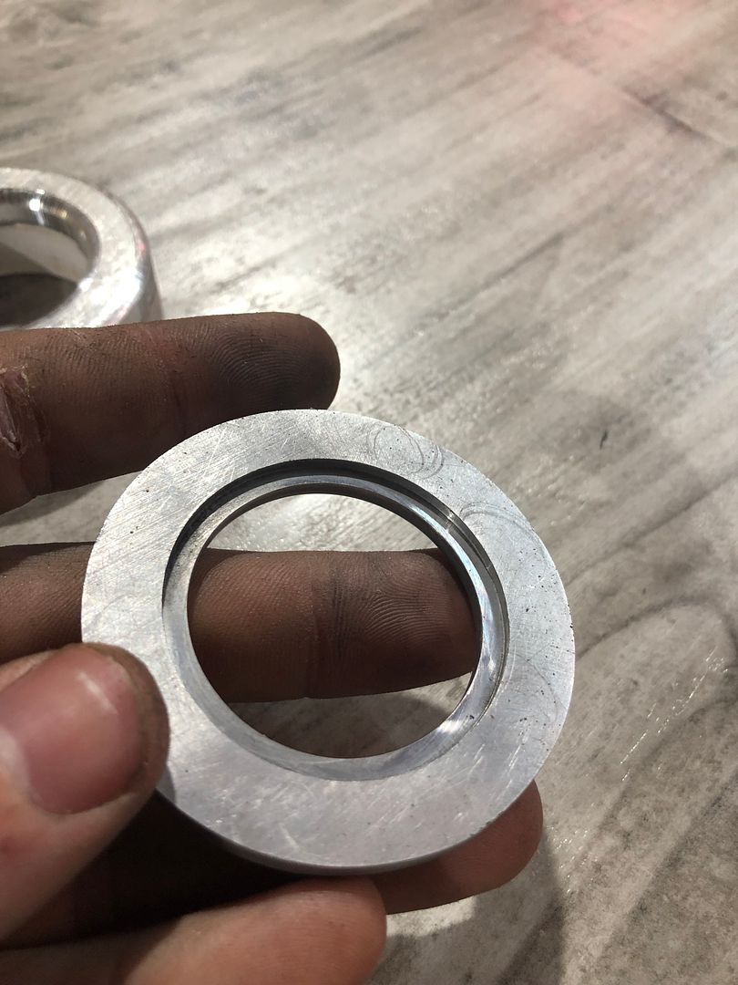
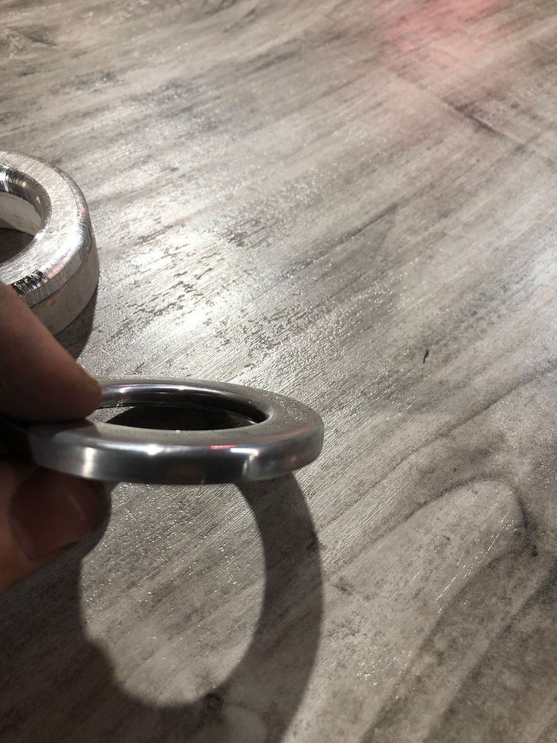
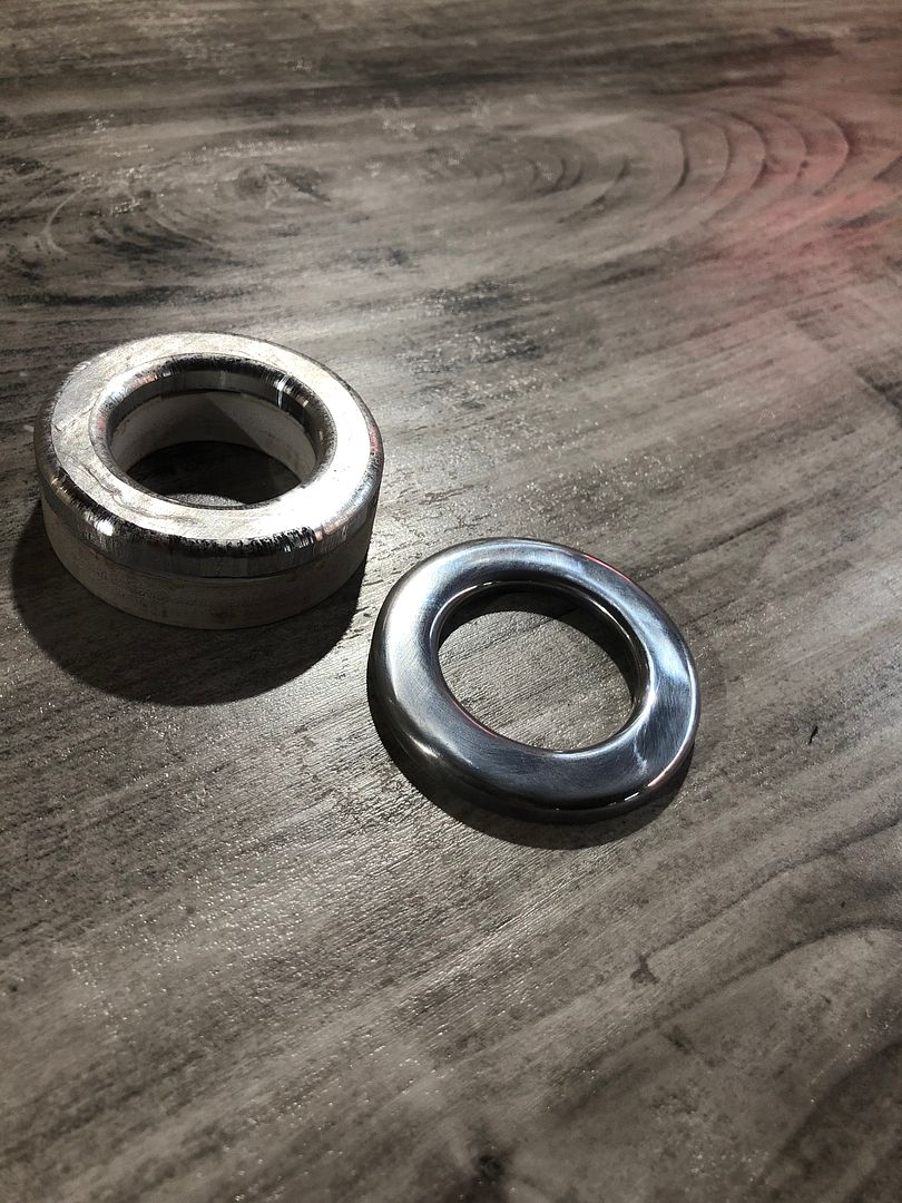
Ideally the inner opening of the ring should rest on the midline of the sleeve. This provides for a good fusion weld and starts the formation of the radius we're looking for around the inside opening. Here's the various stages of welding the escutcheons:
Mike got the remaining openings cut in the arm rest and kick panels for the escutcheons...
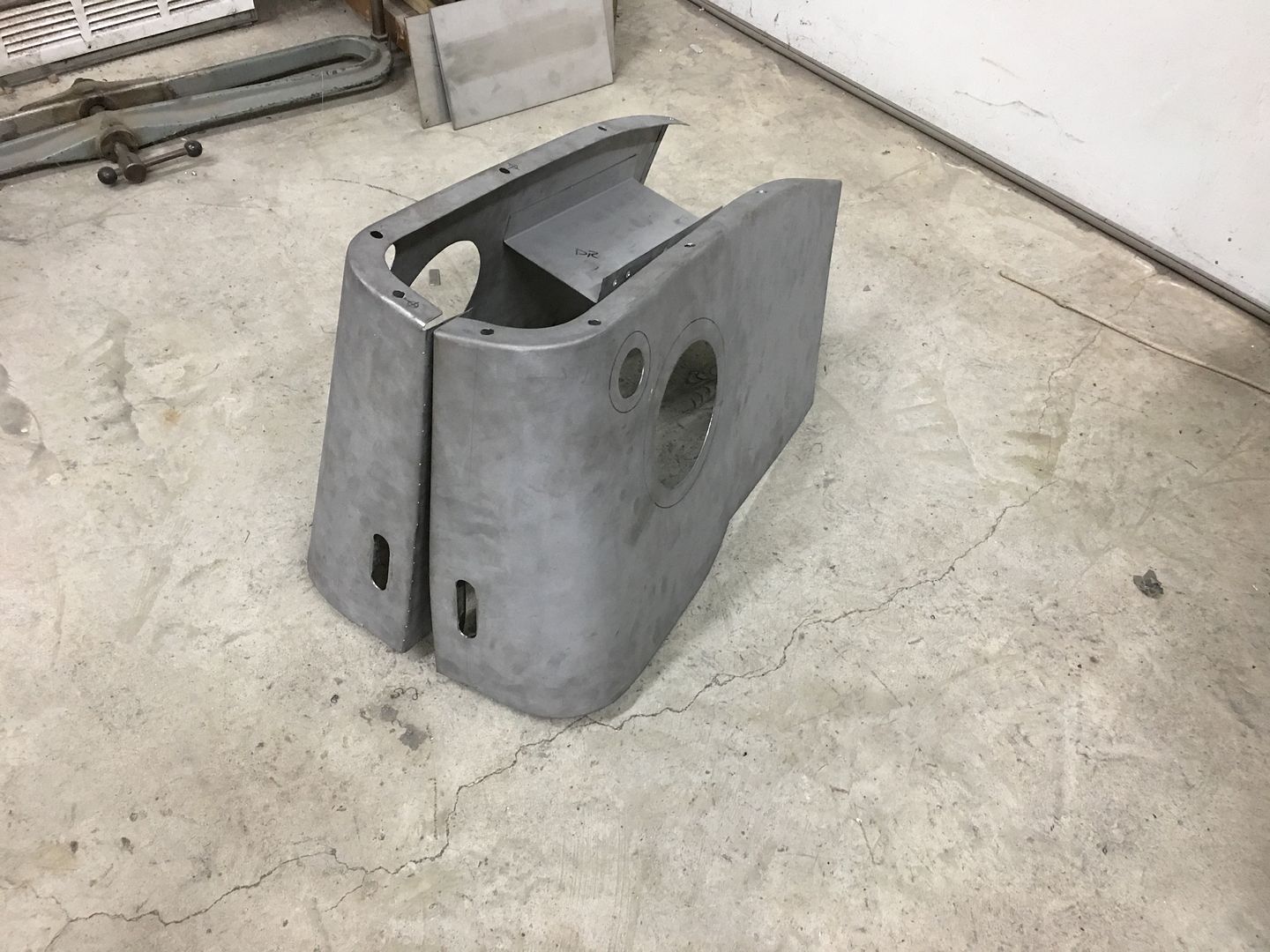
Test fit...
…..and JB got started on the speaker trim rings for us...
The recess on the rear is for the stainless mesh...
Then we contemplated vertical or parallel....
Remaining escutcheons were welded up...
Ideally the inner opening of the ring should rest on the midline of the sleeve. This provides for a good fusion weld and starts the formation of the radius we're looking for around the inside opening. Here's the various stages of welding the escutcheons:
Mike got the remaining openings cut in the arm rest and kick panels for the escutcheons...
Test fit...
…..and JB got started on the speaker trim rings for us...
The recess on the rear is for the stainless mesh...
Last edited:
xtremek
Well-known member
What's going to hold the escutcheons in place? Did I miss that?
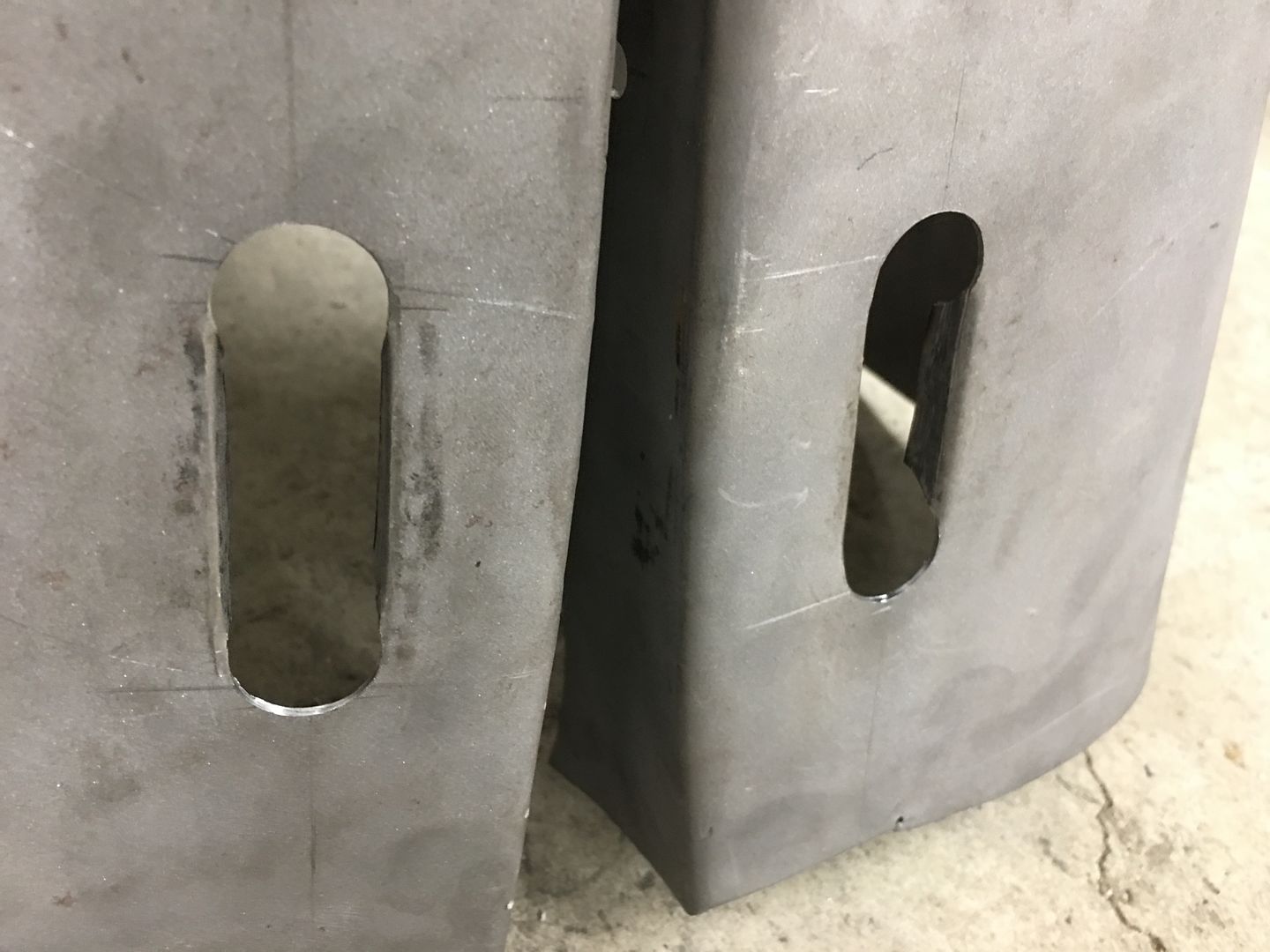
This shows it best, we drilled two holes on either end, a slice down the middle, and the two "flaps" were folded inward. These are fairly snug, but after upholstery is done, we'll push them in where desired, mark the insides where the tab stops, and then grind a groove in the escutcheons for the tab to lock into. Then bend the tabs inward slightly, and install one last time..
In our arm rest two clearance holes are drilled, then a cut made between the two. Next, the two "tabs" are hammered downward to provide the void needed for the escutcheon such that they are tight enough to hold it in place.
xtremek
Well-known member
Got it. thx