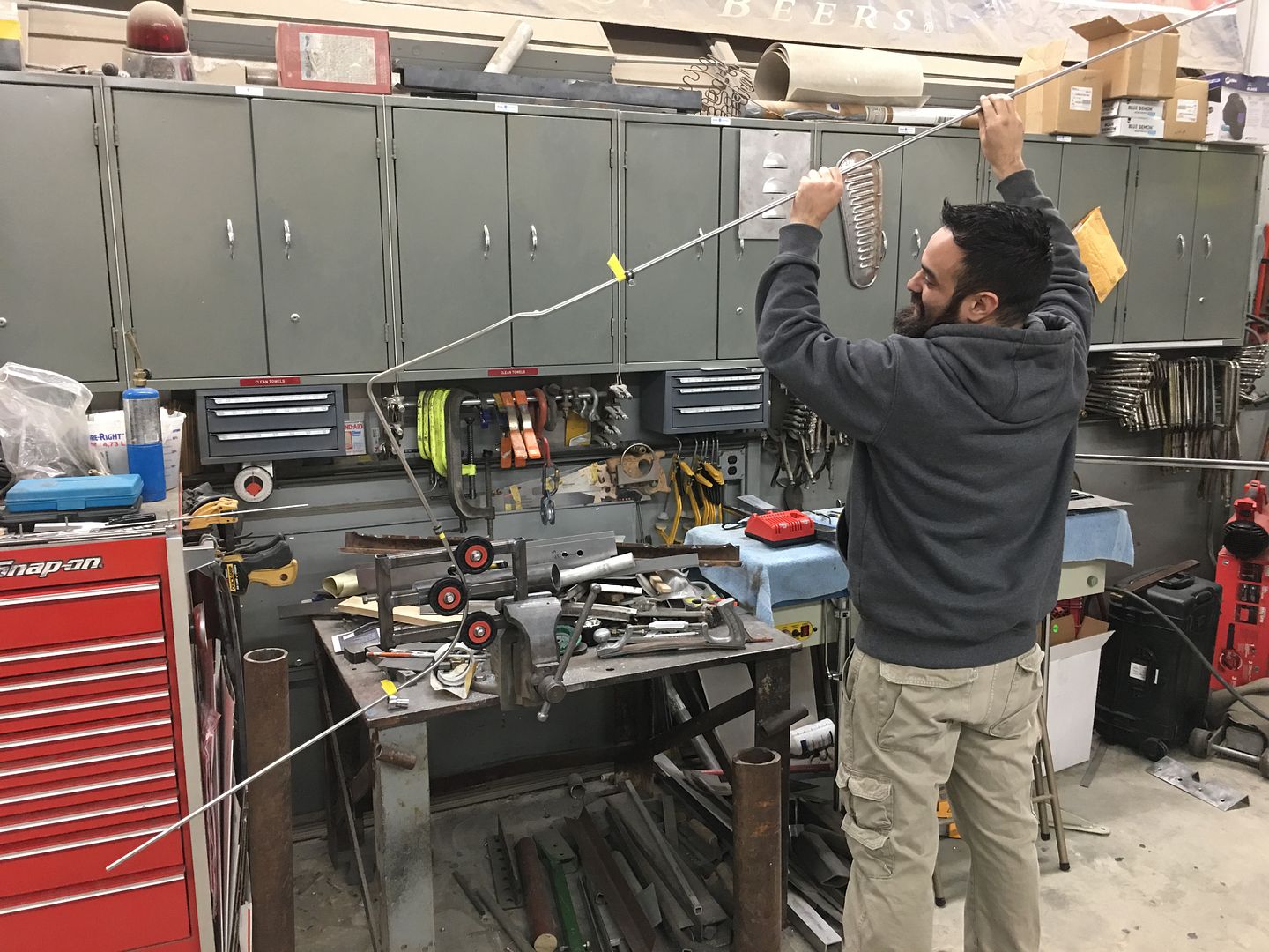
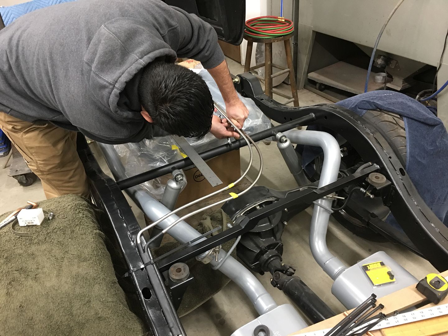
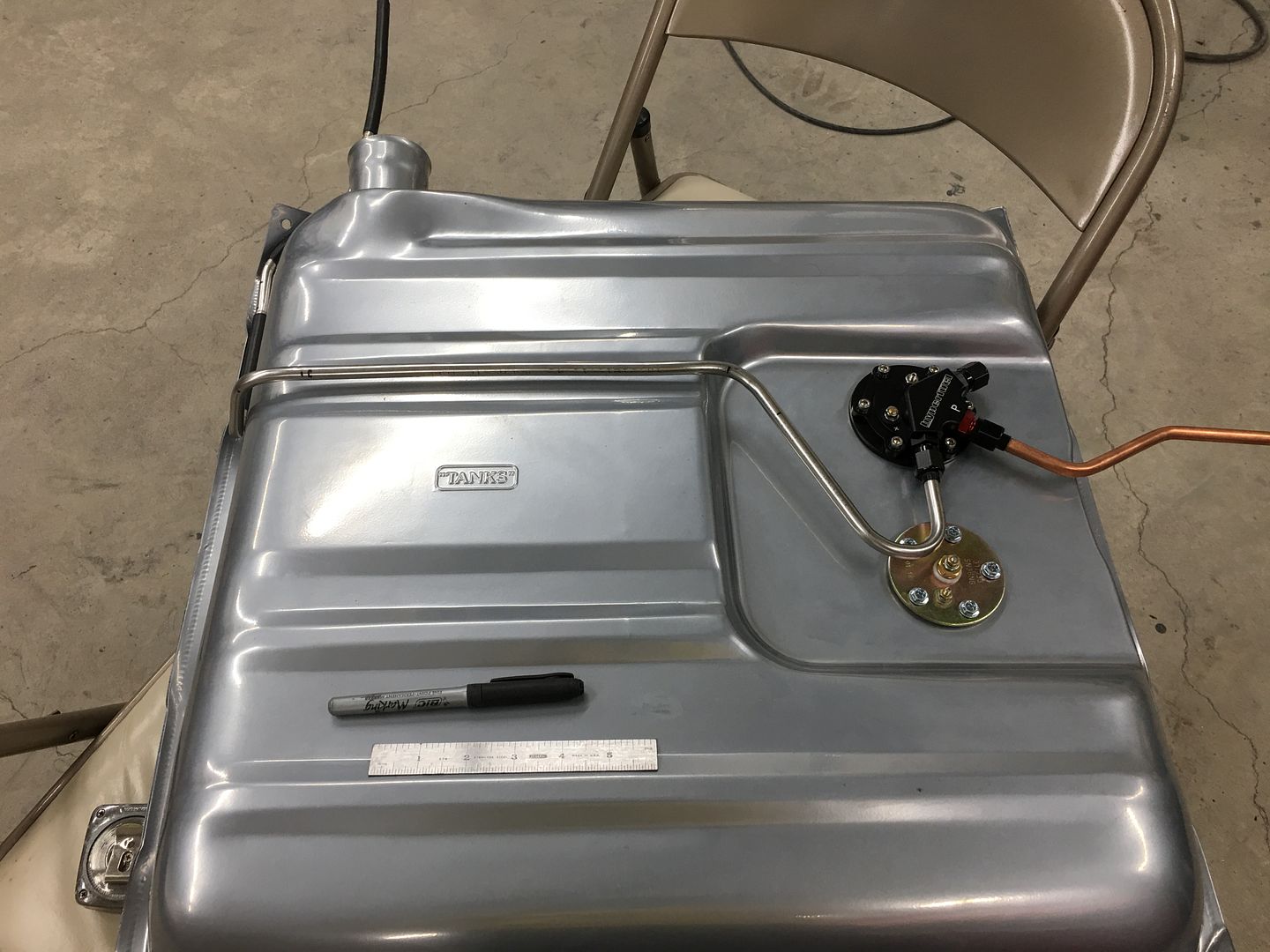
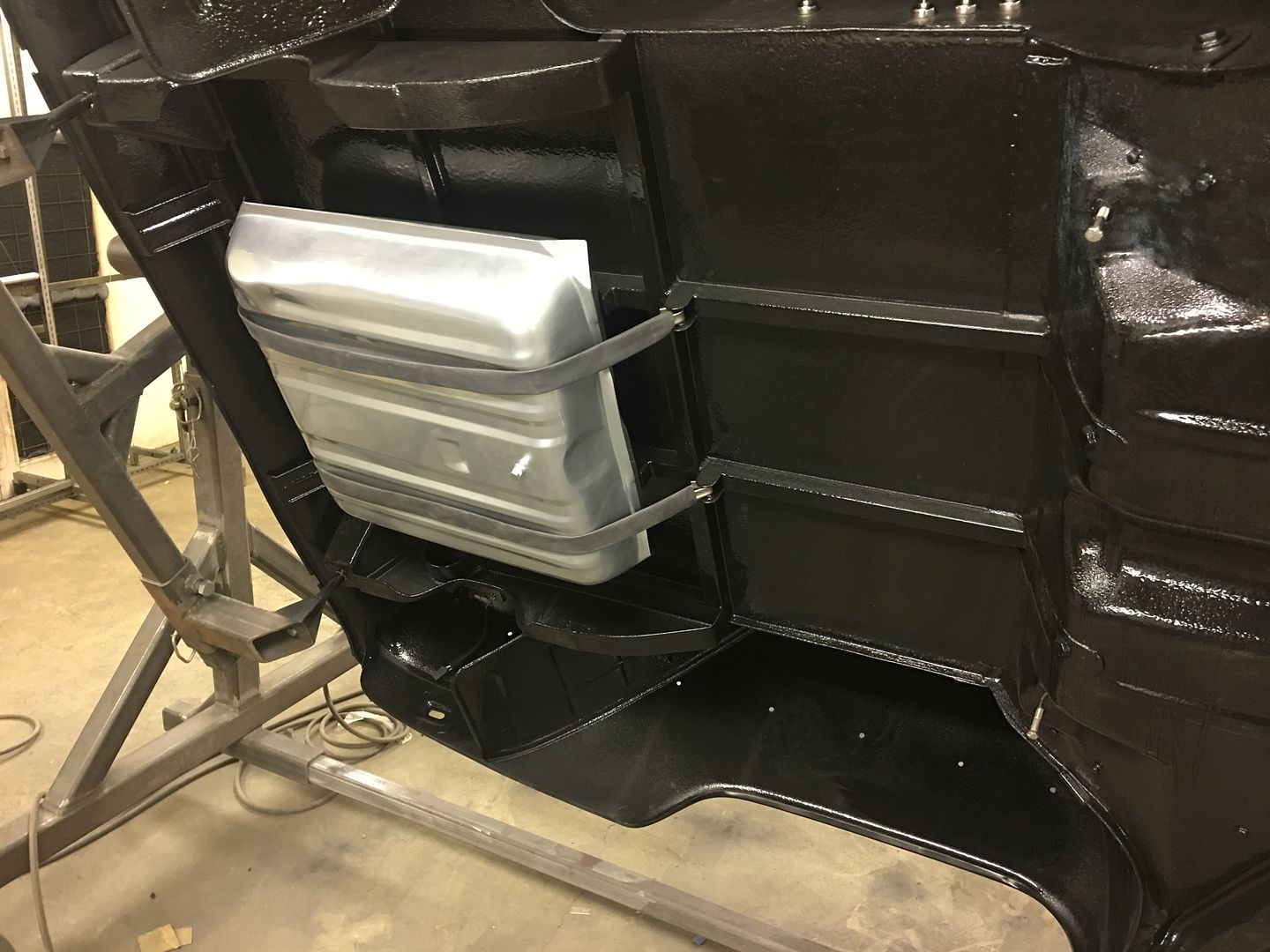
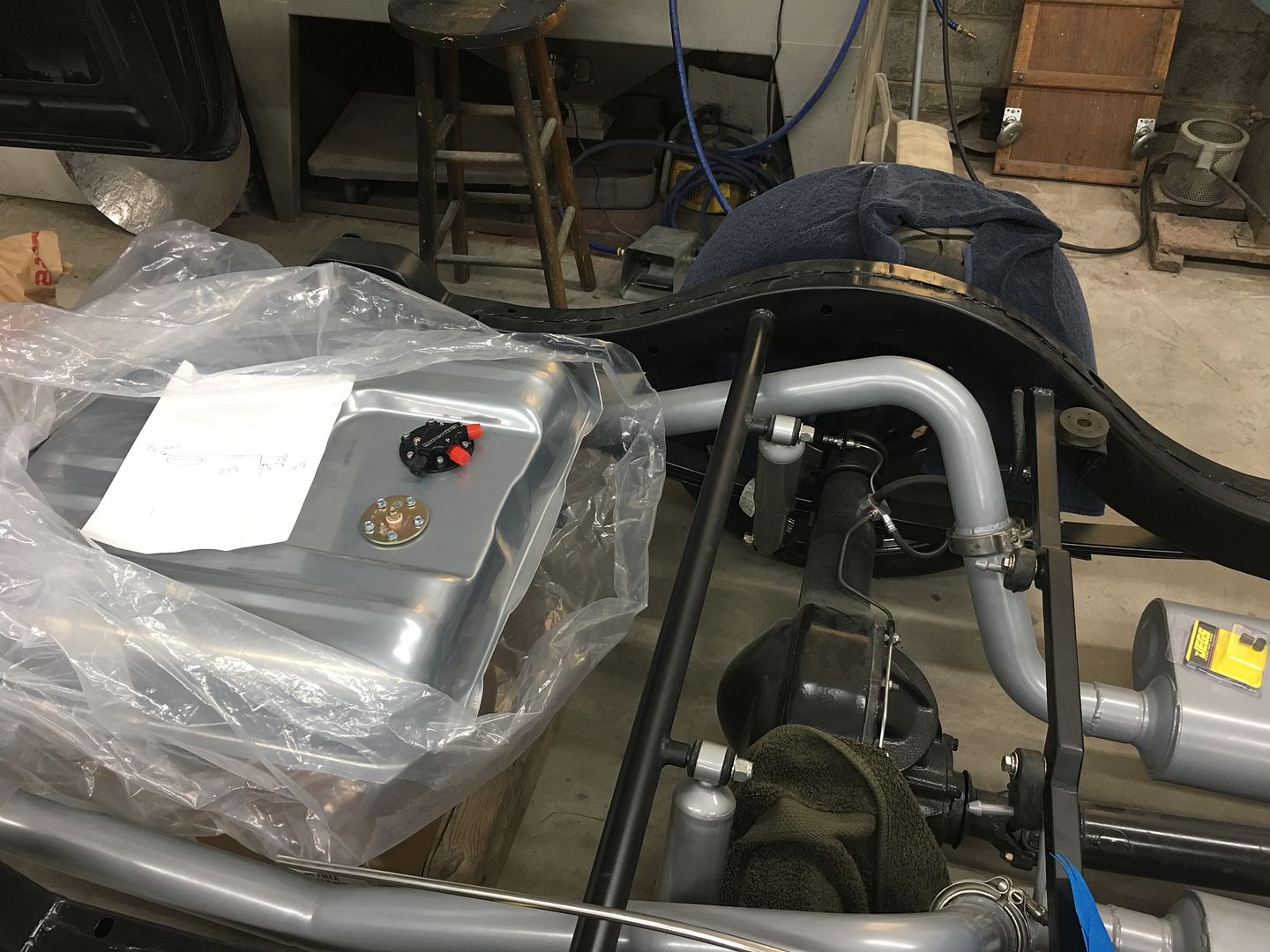
Saturday we got the tank installed so we could get a good reading on where it locates in relation to the body mounts in front of the axle.
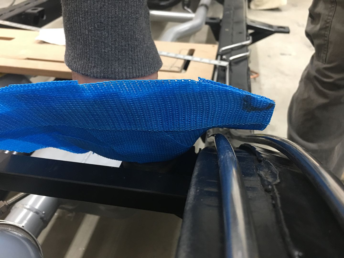
We also pulled a pattern from the body mount so we could bend the lines around it accurately.
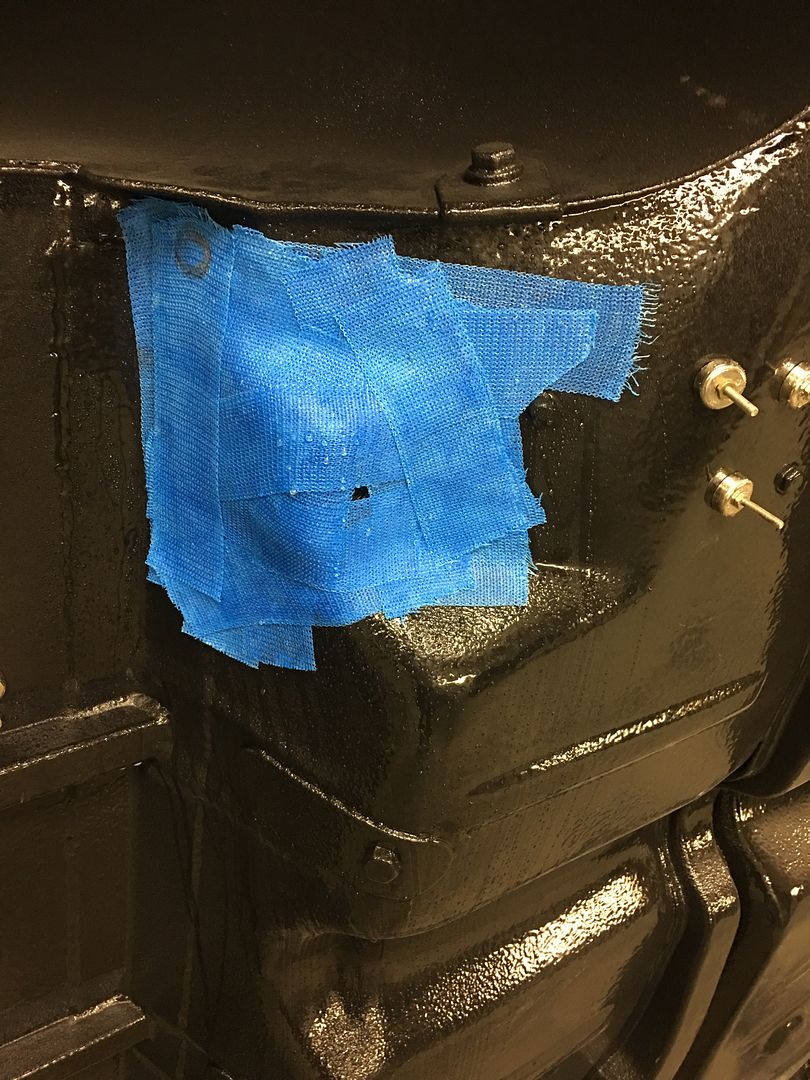
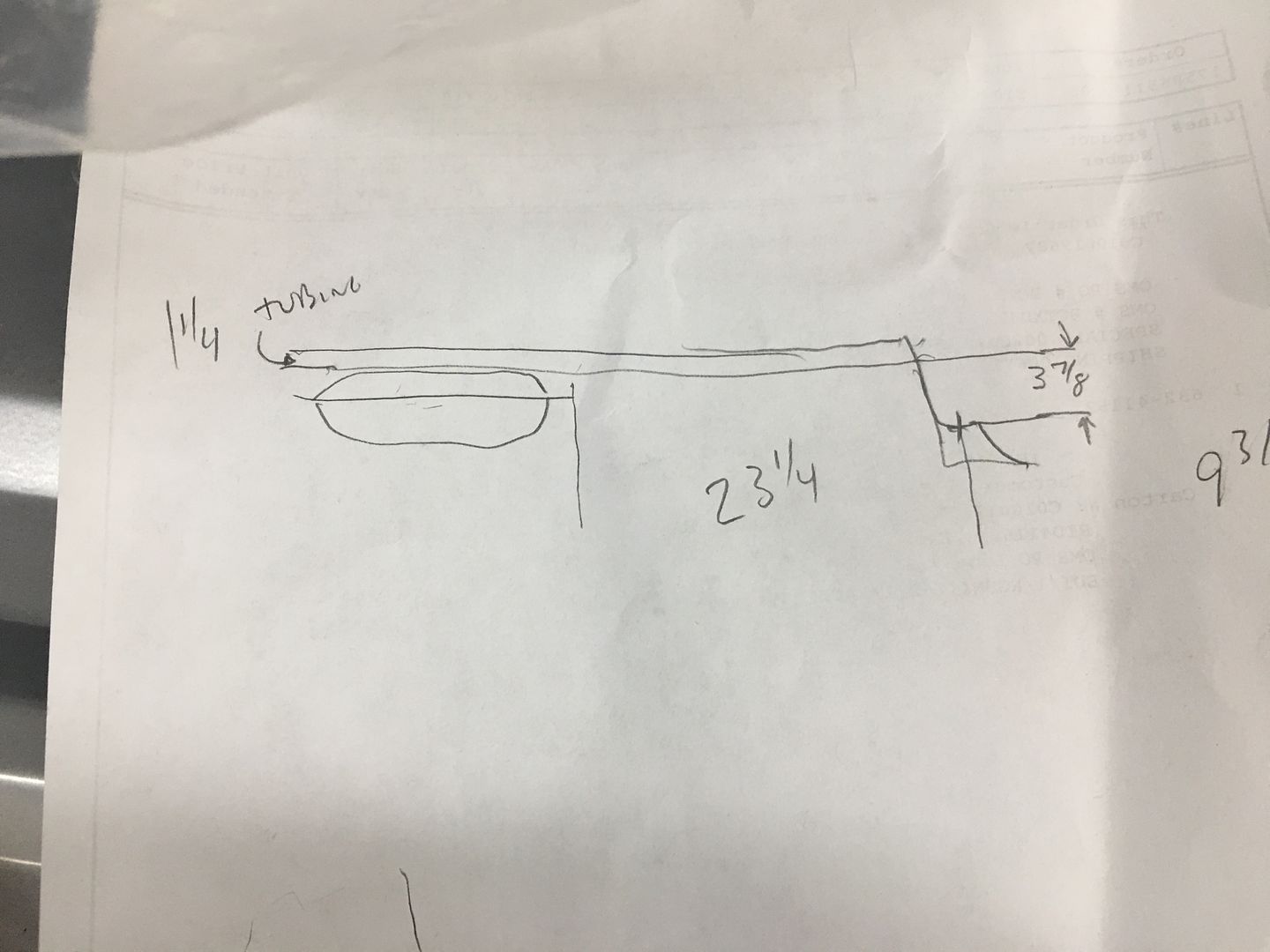
Highly technical drawing showing our tank location...
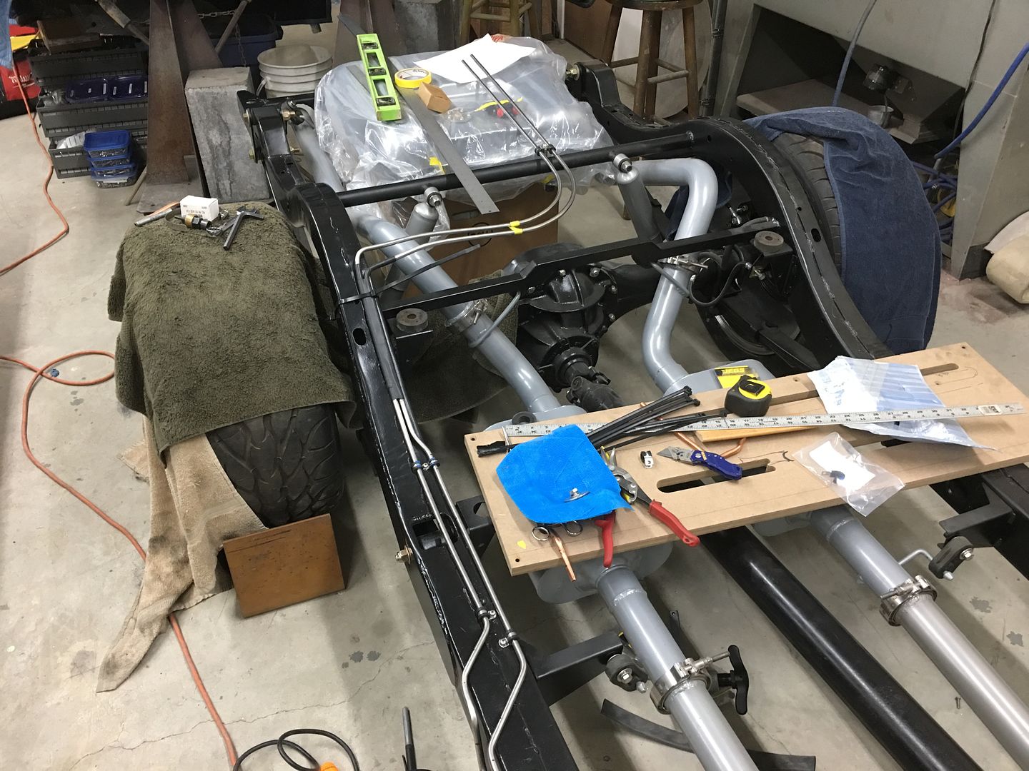
Tank located per our drawing in relation to body mount..
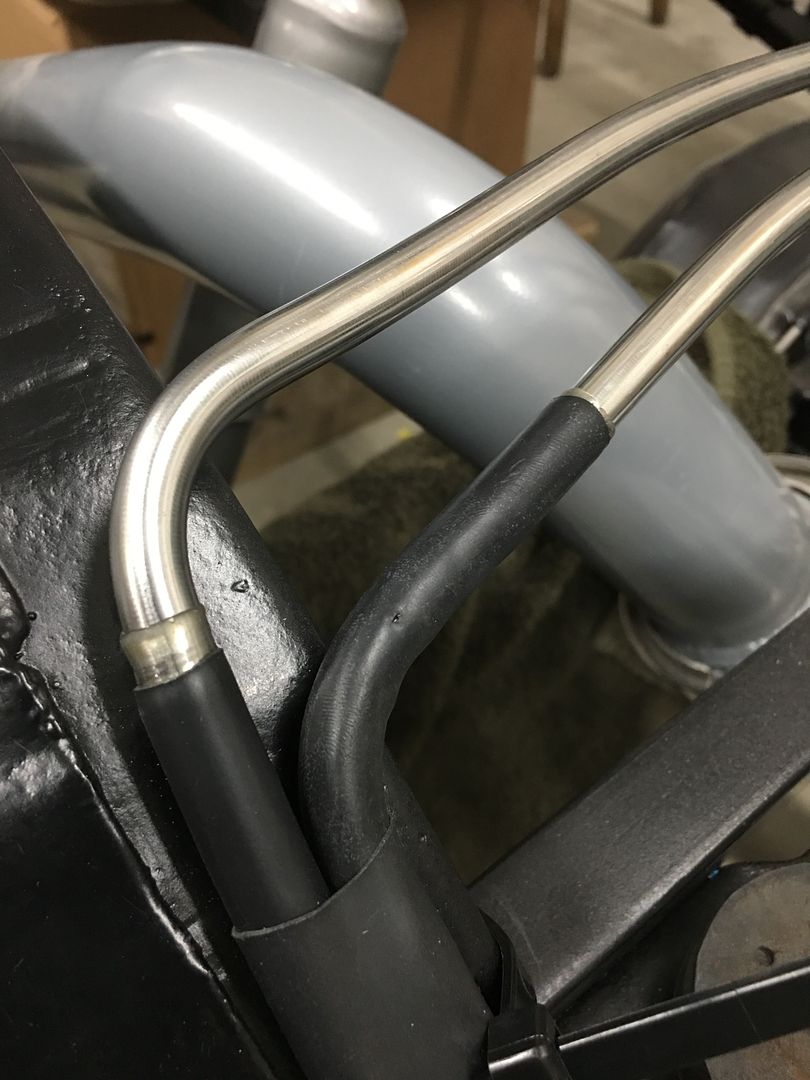
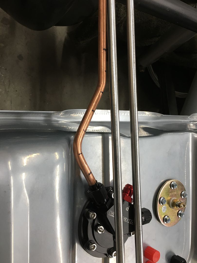
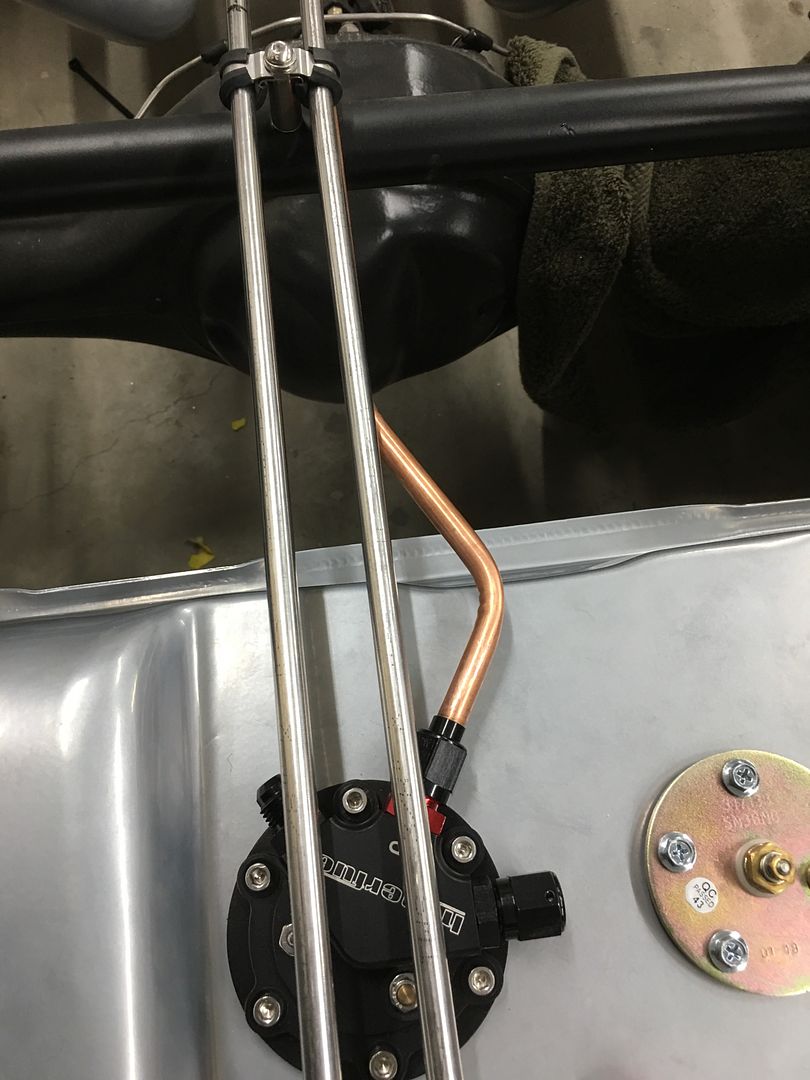
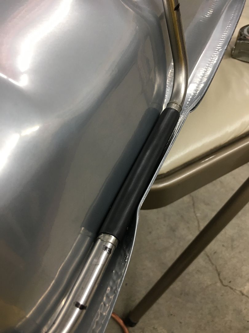
The more I look at this, the less I wanted to use the braided lines between the hard line and the tank. I'm just not comfortable with another fitting in the vicinity of the tail pipes. So back up and punt, looks like we're getting new tubing and bending again. The last lines weren't long enough to make it back to the tank, so we'll chalk them up as practice pieces, learning curve, if you will...
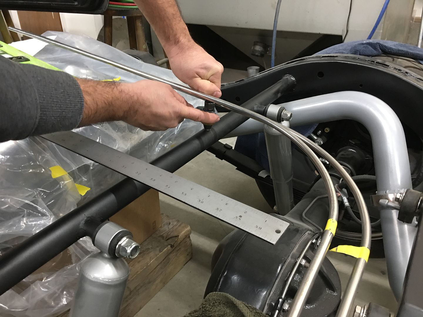
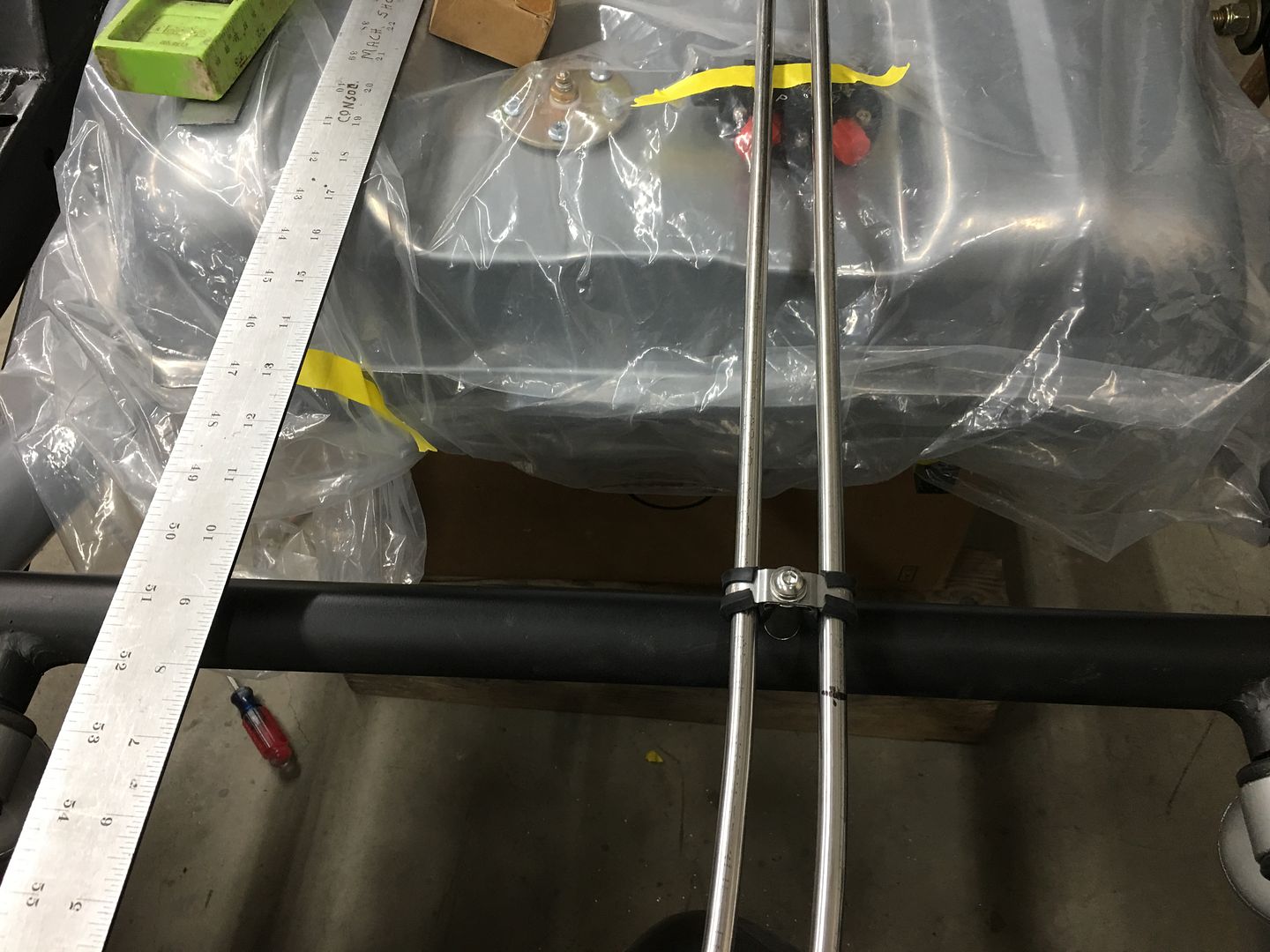
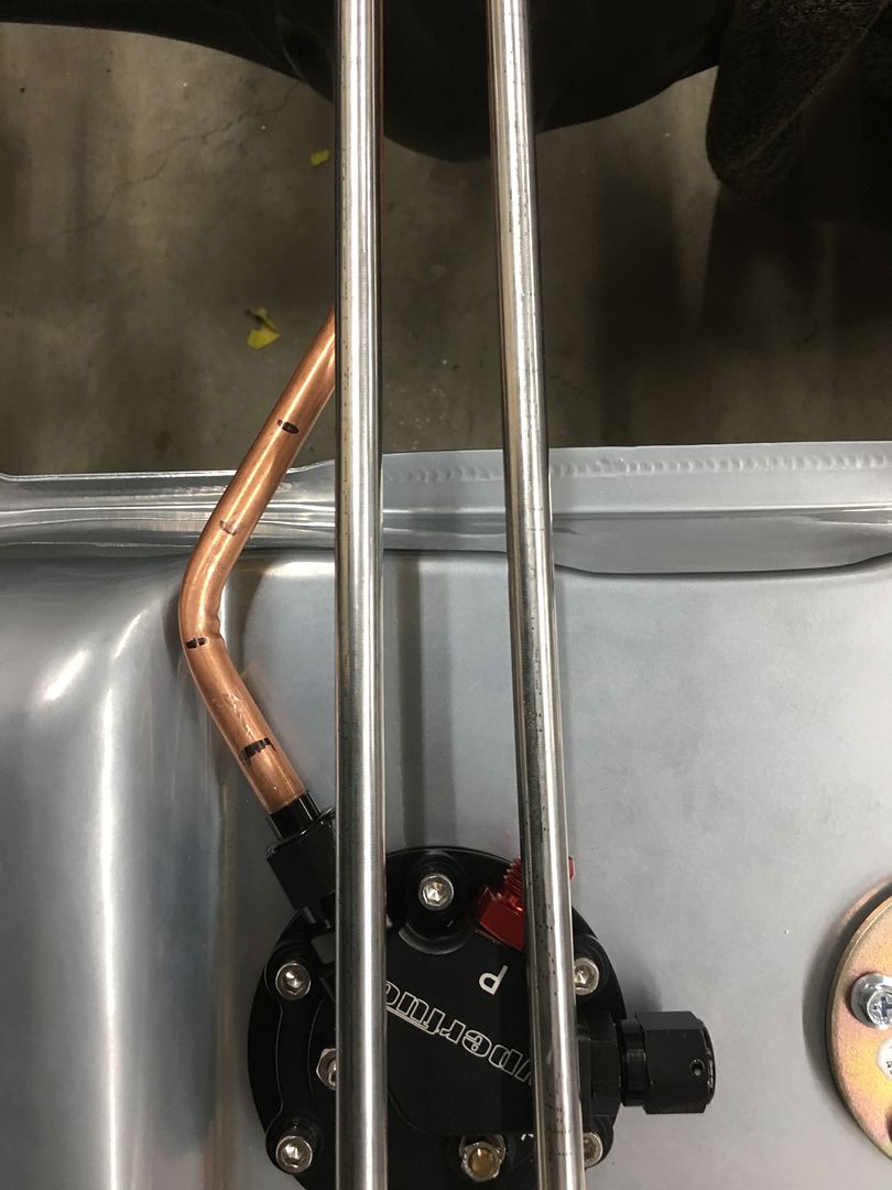
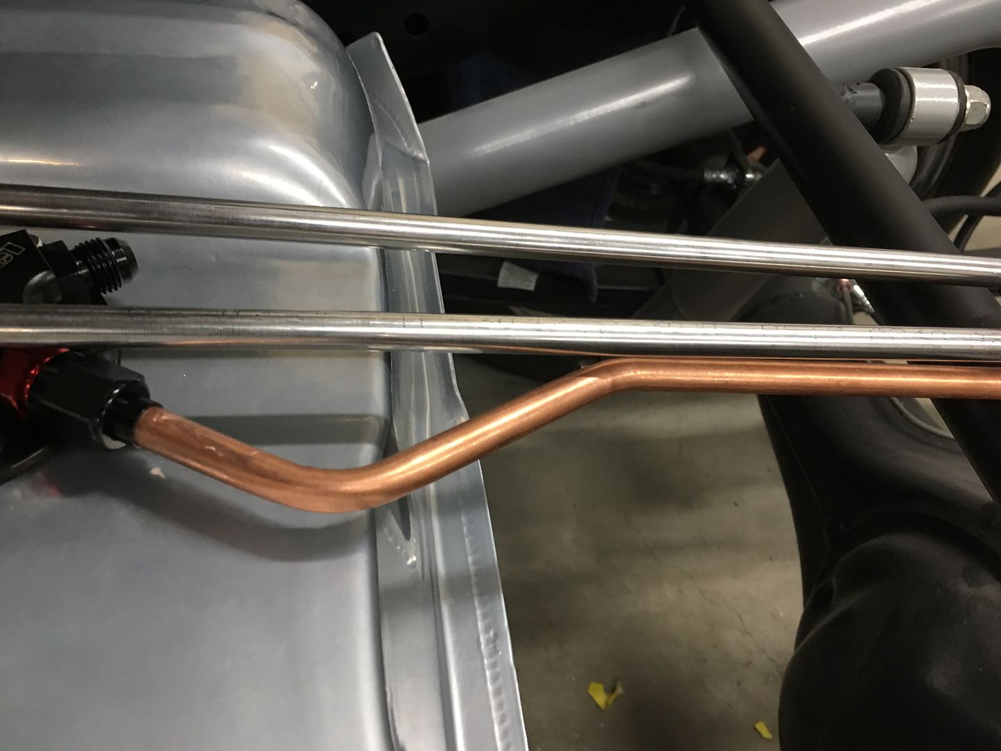
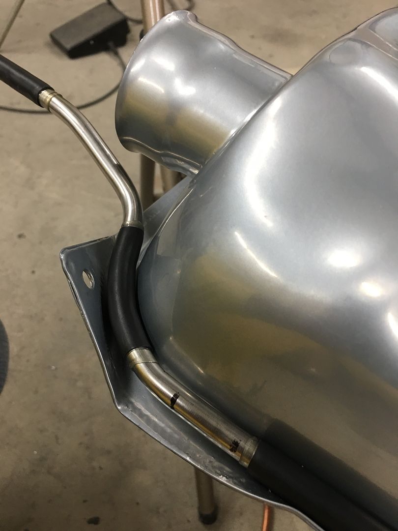
Here the Body mount pattern is bolted up, the lines will make a bend behind this body mount, travel across to the middle, and then toward the back where it will attach directly to the tank.
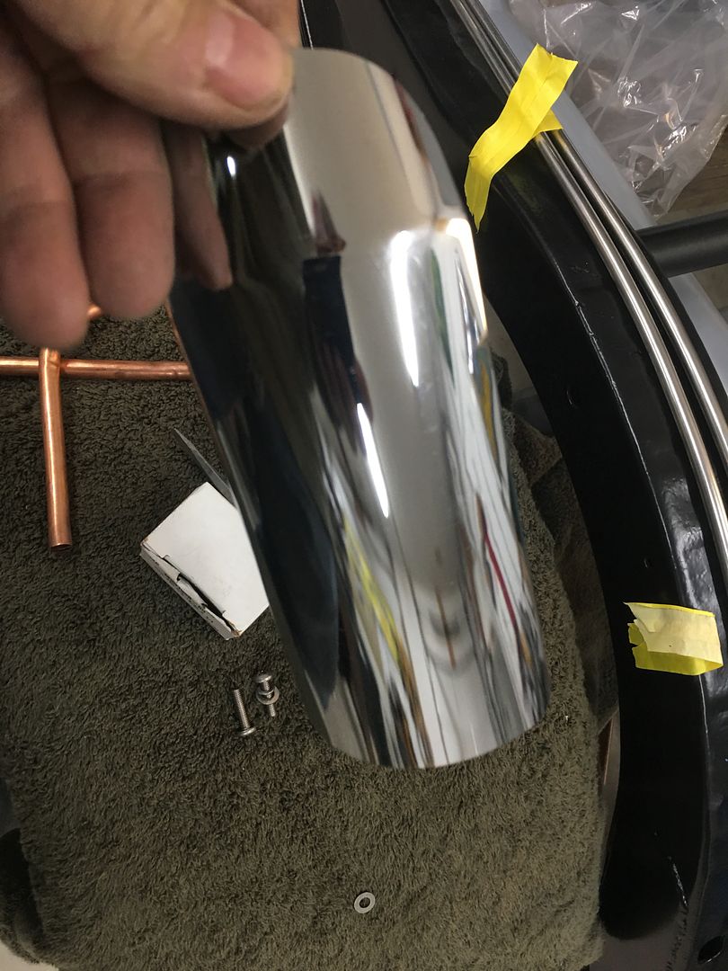
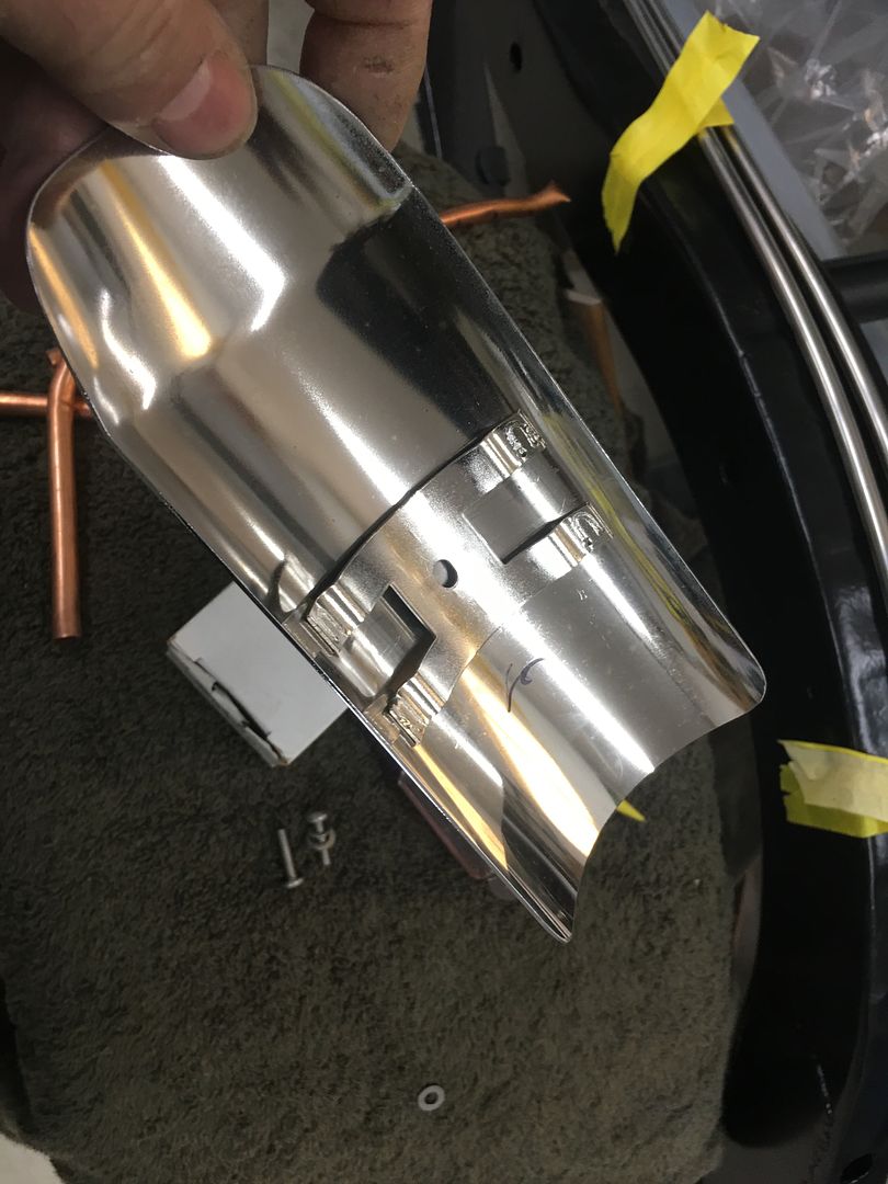
The lines will come close to the passenger tail pipe, so we'll add a heat shield. I visited a local motorcycle shop and picked up a donor...
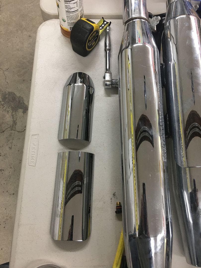
trimmed to fit...
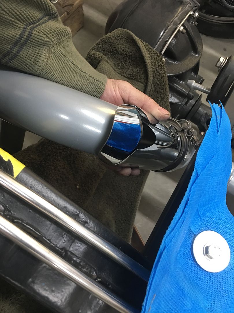
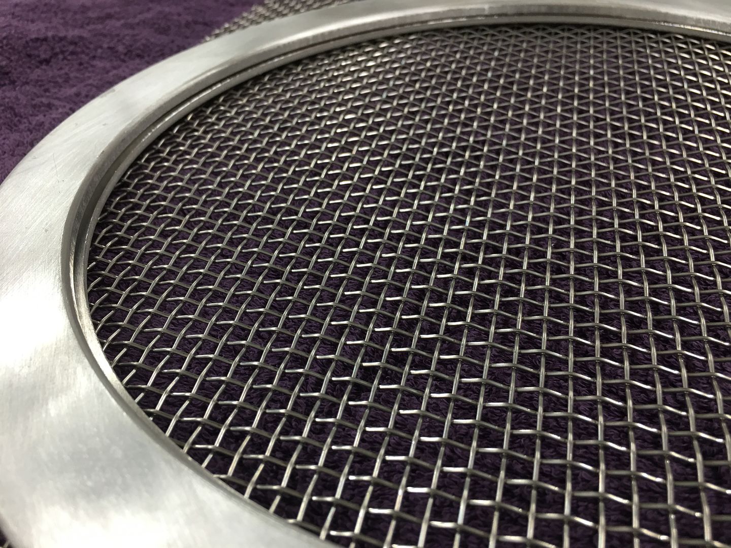
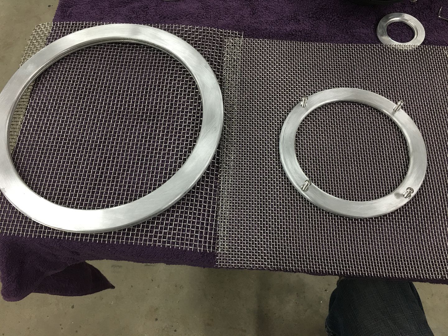
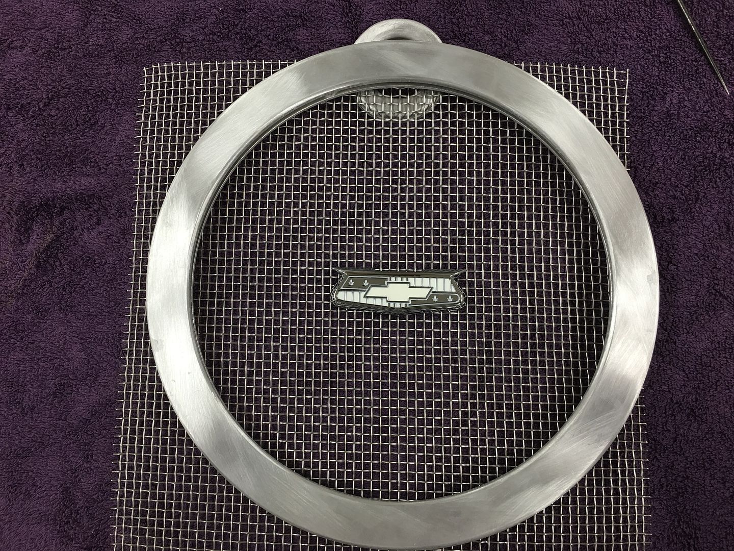
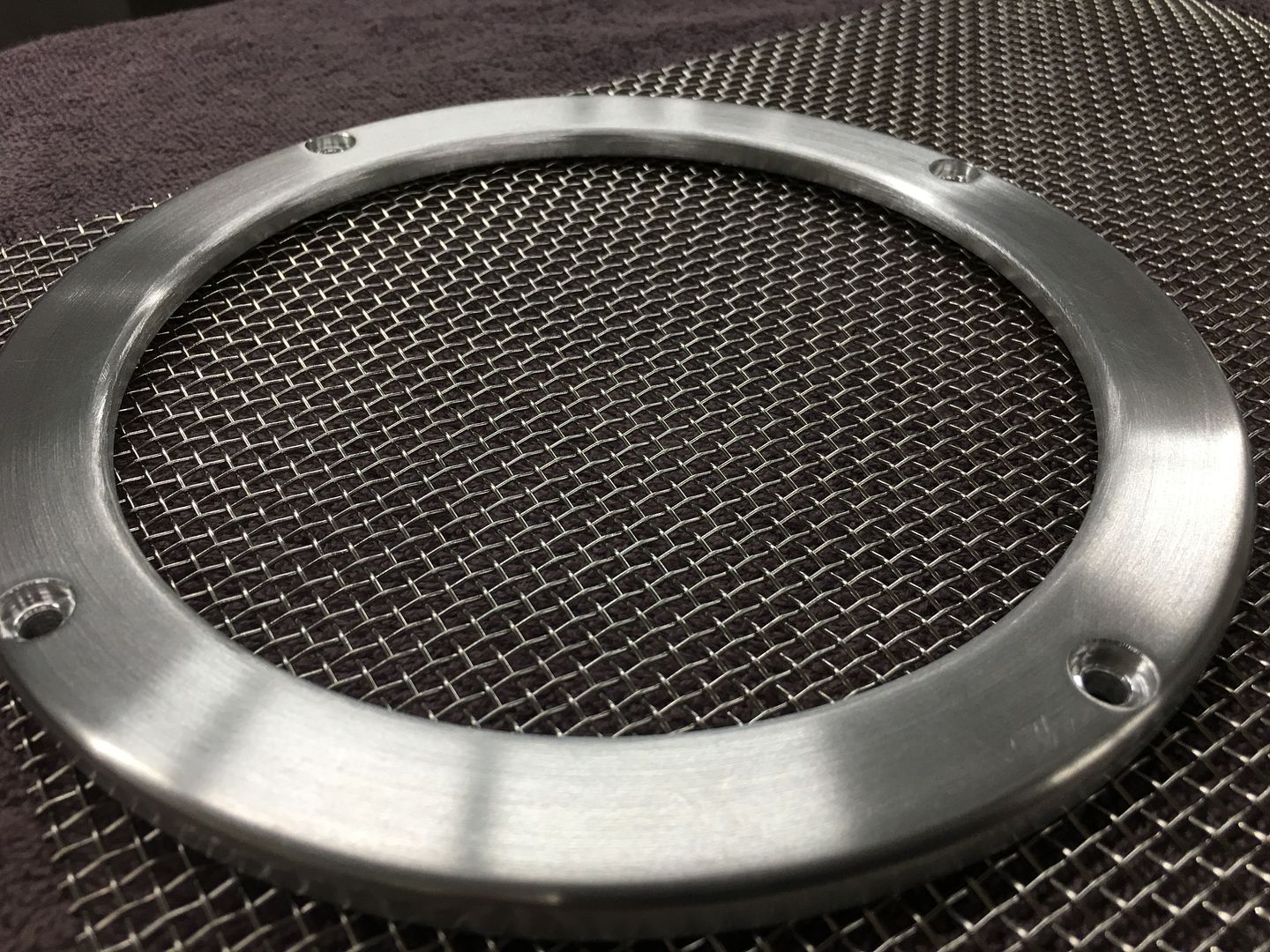
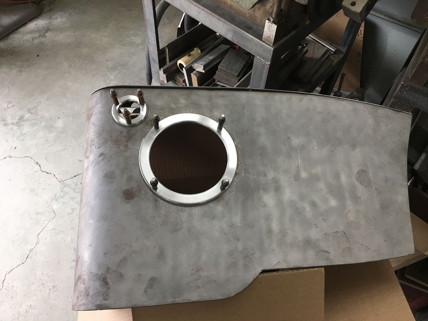
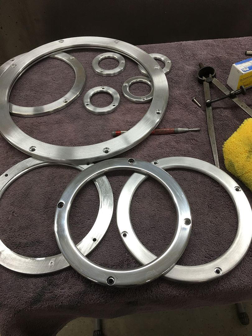
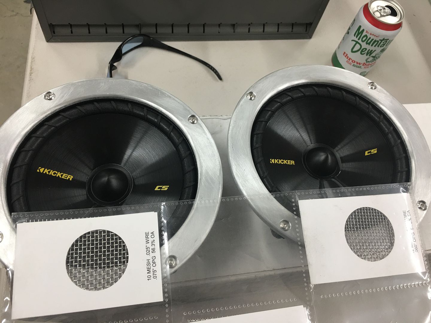
That should do. Next, we need to finish the kick panels for upholstery, which means mounting the speakers. The trim rings from cousin JB will need holes drilled to match the speakers. We have some button head allen screws we plan on using, but didn't really care for the surface mounted look...
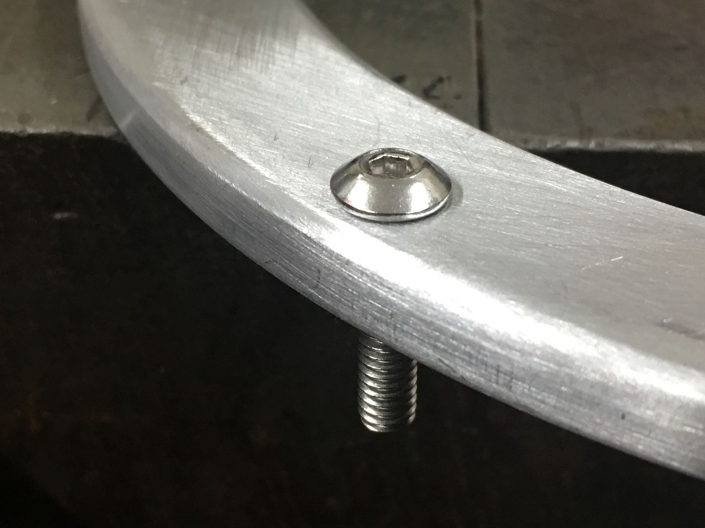
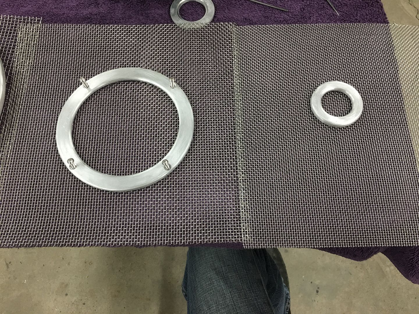
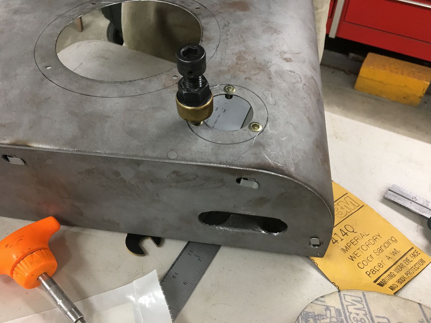
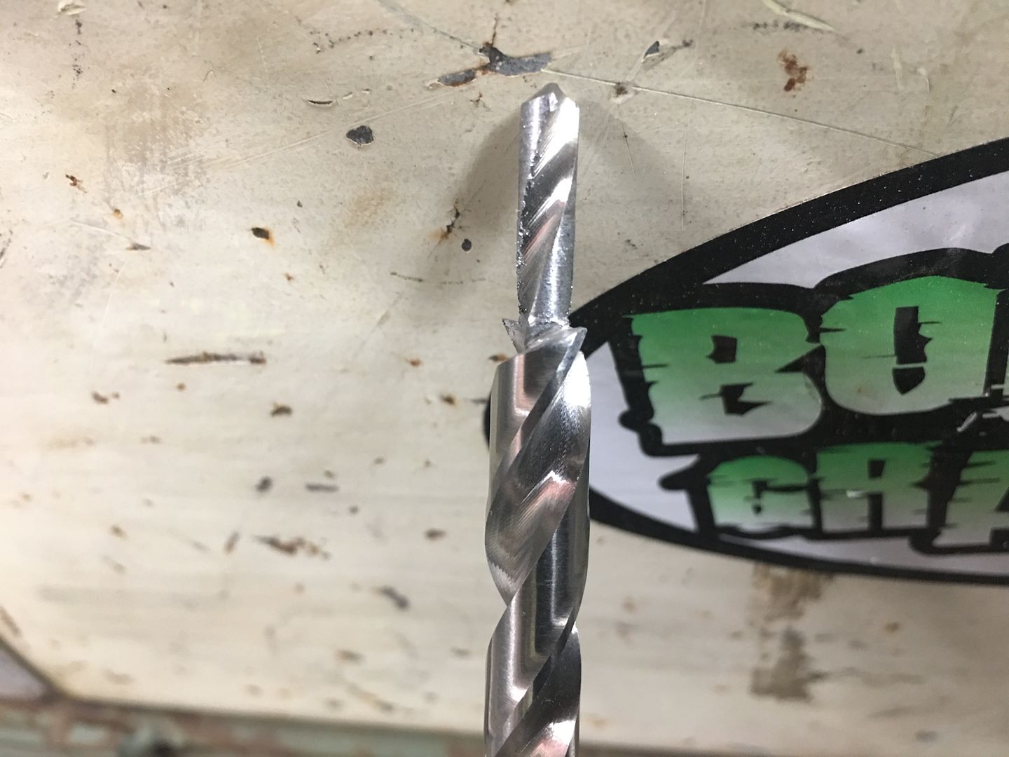
This would look so much better with the details of counterbored holes. Alas, the pitfalls of working on Saturdays without a local source. What's a person to do but make their own. The extended die grinder almost fits the Aloris tool holder too well, like it was made to be.
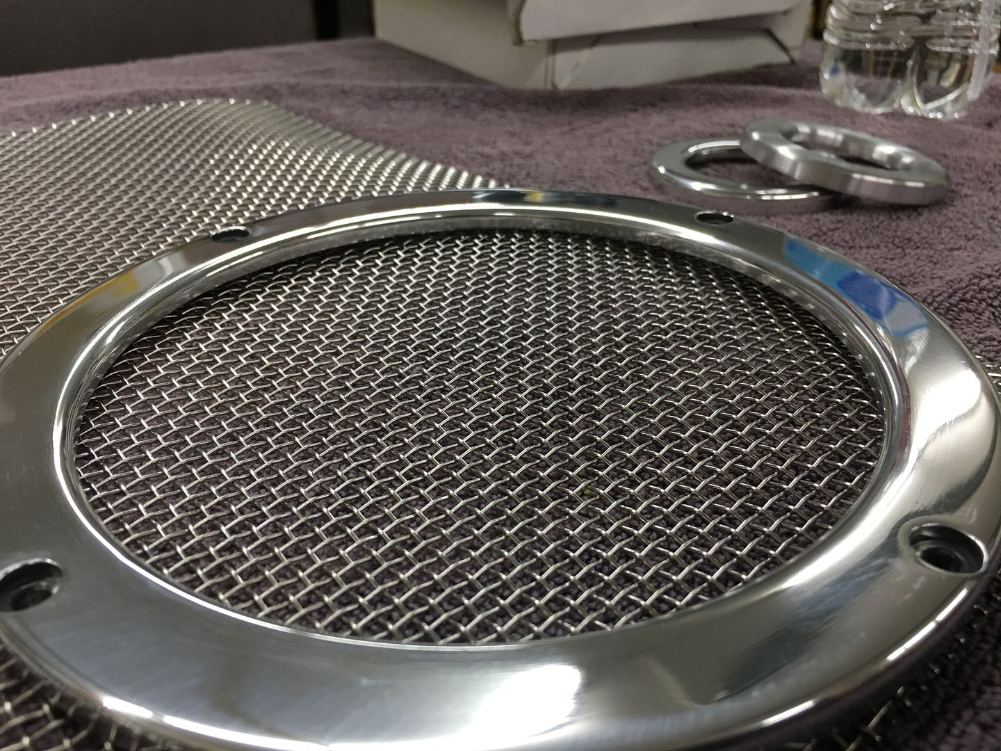
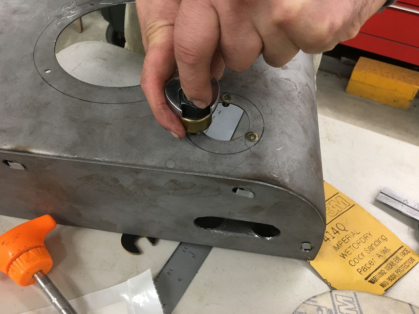
A 120 grit roloc sanding disc does well to backface the cutting edge and we are in business..
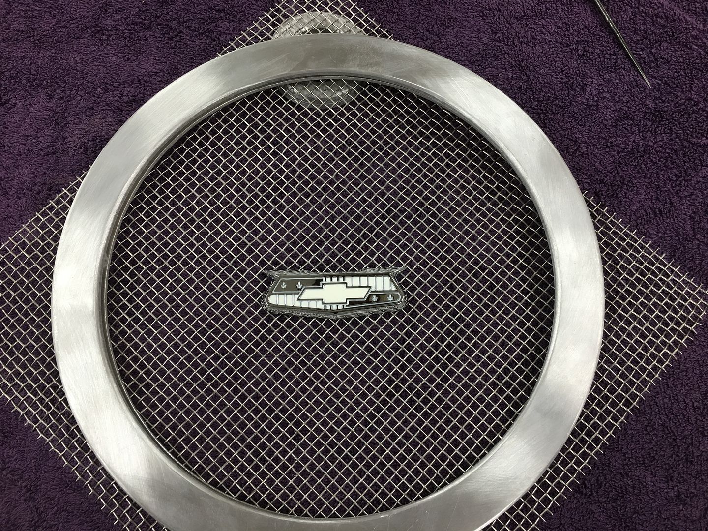
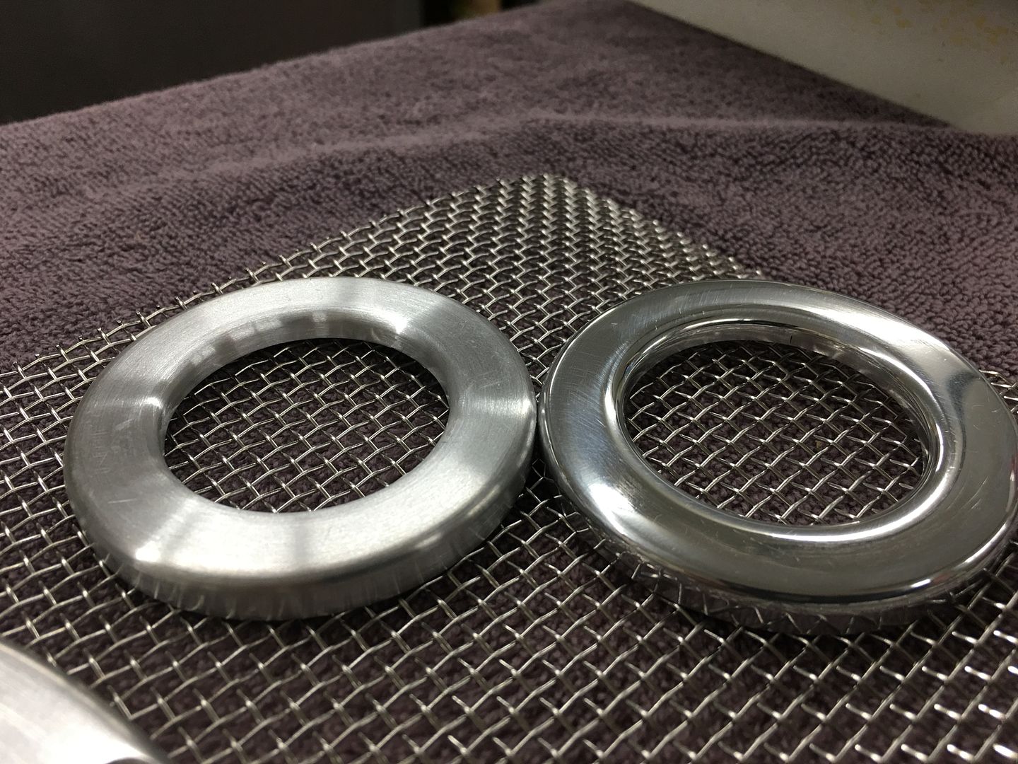
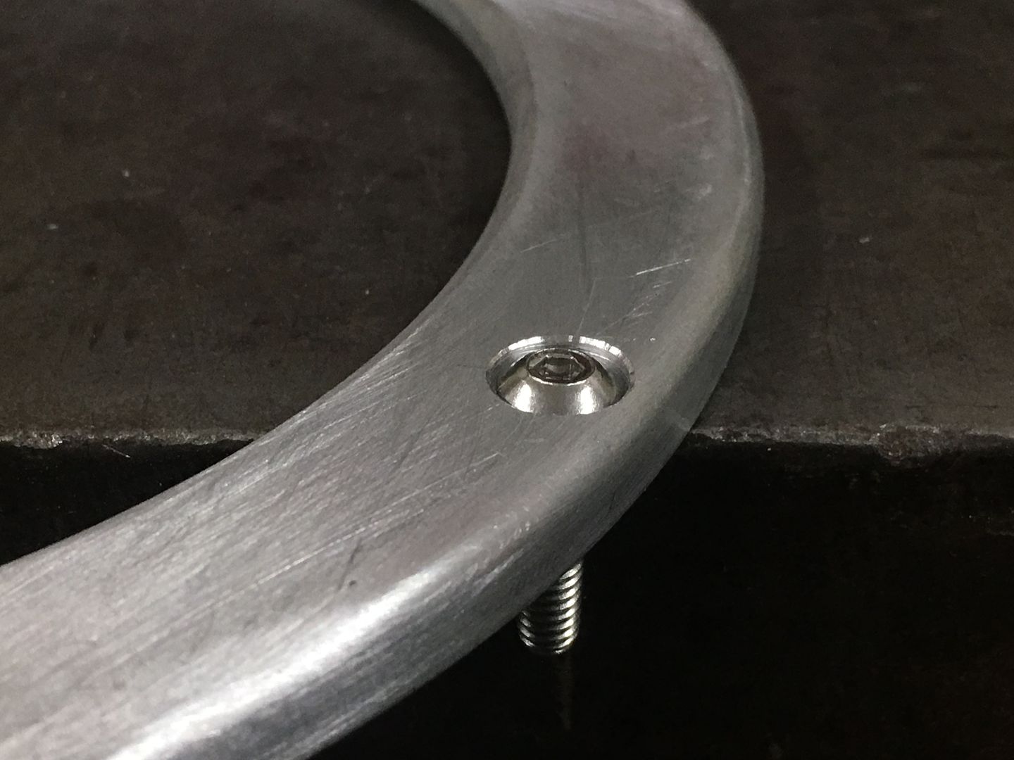
Much better, all in the details..
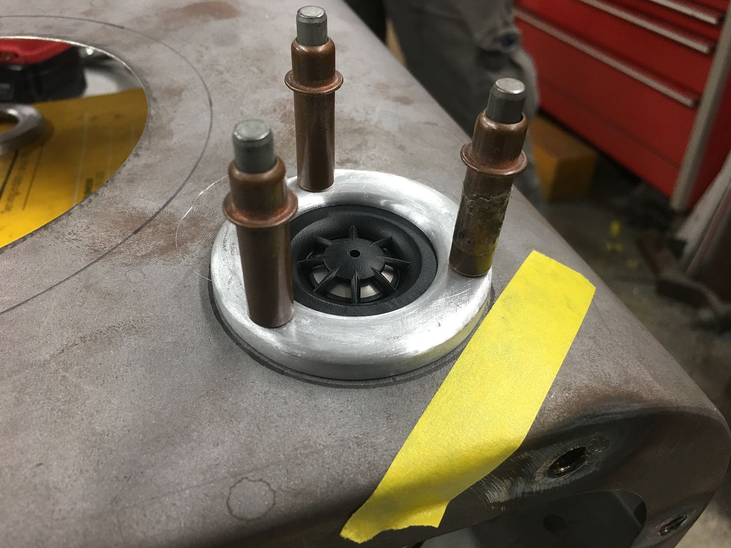
….and adding the tweeters to the kick panel...
We also pulled a pattern from the body mount so we could bend the lines around it accurately.
Highly technical drawing showing our tank location...
Tank located per our drawing in relation to body mount..
The more I look at this, the less I wanted to use the braided lines between the hard line and the tank. I'm just not comfortable with another fitting in the vicinity of the tail pipes. So back up and punt, looks like we're getting new tubing and bending again. The last lines weren't long enough to make it back to the tank, so we'll chalk them up as practice pieces, learning curve, if you will...
Here the Body mount pattern is bolted up, the lines will make a bend behind this body mount, travel across to the middle, and then toward the back where it will attach directly to the tank.
The lines will come close to the passenger tail pipe, so we'll add a heat shield. I visited a local motorcycle shop and picked up a donor...
trimmed to fit...
That should do. Next, we need to finish the kick panels for upholstery, which means mounting the speakers. The trim rings from cousin JB will need holes drilled to match the speakers. We have some button head allen screws we plan on using, but didn't really care for the surface mounted look...
This would look so much better with the details of counterbored holes. Alas, the pitfalls of working on Saturdays without a local source. What's a person to do but make their own. The extended die grinder almost fits the Aloris tool holder too well, like it was made to be.
A 120 grit roloc sanding disc does well to backface the cutting edge and we are in business..
Much better, all in the details..
….and adding the tweeters to the kick panel...