To avoid these ads, REGISTER NOW!

My design for a single post hydraulic press

ert01

Well-known member
Joined
Jun 26, 2011
Messages
151
I've used my old Princess Auto 12T press to do enough u-joints that it's paid for itself 5x over... All that use made me think about what I actually need a press for and what sort of design might be better in my garage.

So today during my breaks I put pencil to paper and came up with a design.

Feel free to critique it and revise it. Note that the top section that supports the jack will be fully boxed in with 1/4" plate in the final execution.

I already have a pneumatic jack that I modified for inverted use. As a note to anyone who tries to modify these jacks for inverted use, there are two separate intake ports in the base. One is for the manual pump and one is for the air motor. A snorkel must be added to BOTH of these intakes.

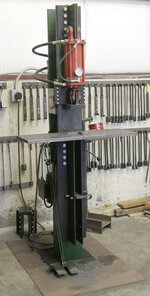
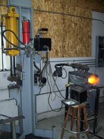
Anyways... Here's the pics of my current progress:

ruhu4u9e.jpg


ave9yjyg.jpg


emeqe4us.jpg


Note the spider gear welded onto the release valve :) (I'm a jeep guy and I always have a full stock of spider gears in my shop. I've found they make awesome handles for many shop tools)
 
Last edited:
To avoid these ads, REGISTER NOW!
OP
E

ert01

Well-known member
Joined
Jun 26, 2011
Messages
151
Oh and I will add a slider to the head of the press to help keep the deflection to a minimum.

The presses I've pictured below have sliders kinda like what I'm thinking:

ge3ubeve.jpg

yge7ypap.jpg

y6u8ahah.jpg
 

bsaint

Well-known member
Joined
Apr 26, 2010
Messages
5,109
Location
Manchester, CT
In the industry we call this a C-frame machine. Came out great. This is what I would want to make instead of H-frame.
 
OP
E

ert01

Well-known member
Joined
Jun 26, 2011
Messages
151
Before I went into the trades, I was an illustrator. I used computers for a lot of my work, but I have always preferred pencil and paper.

It does look a lot like a log splitter :) in researching my project I came across a few guys who converted 30T log splitters into presses. I think it's a great idea... I'm just cheap and I had all this steel laying around. My only cost is the jack and it's pretty cheap when it goes on sale.

I like this design better then an h frame design because it is a lot more open and allows a wider range of material positioning and at the same time it takes up less real estate in my garage. I will be making a foot switch for it too in the future. Should make u-joint changes a breeze!

Here's a question for you guys though... If I were to drill and thread the base of the jack to install a pressure gauge, how do I do the calculation to convert PSI to tonnage of force? I'd like to put a pressure gauge on the press and pre-mark the gauge to show tonnes instead of PSI.
 

agoins

Well-known member
Joined
Apr 27, 2011
Messages
55
Location
Knoxville, TN
Before I went into the trades, I was an illustrator. I used computers for a lot of my work, but I have always preferred pencil and paper.

It does look a lot like a log splitter :) in researching my project I came across a few guys who converted 30T log splitters into presses. I think it's a great idea... I'm just cheap and I had all this steel laying around. My only cost is the jack and it's pretty cheap when it goes on sale.

I like this design better then an h frame design because it is a lot more open and allows a wider range of material positioning and at the same time it takes up less real estate in my garage. I will be making a foot switch for it too in the future. Should make u-joint changes a breeze!

Here's a question for you guys though... If I were to drill and thread the base of the jack to install a pressure gauge, how do I do the calculation to convert PSI to tonnage of force? I'd like to put a pressure gauge on the press and pre-mark the gauge to show tonnes instead of PSI.

Area of cylinder in square inches * PSI = lbs of force. :bounce:
3.14* inside radius of cylinder * inside radius of cylinder * PSI = lbs of force.
 

bimmer1980

Well-known member
Joined
Feb 5, 2009
Messages
2,105
Location
York, PA
I would recommend changing the design of your top cylinder mount. Look at the other presses and how there ram is attached. My concern with your design is that it will have a tendency to bend the flanges of the I-beam. An I-beam was not designed to take that kind of load.

Either using another short piece of i-beam mounted to the main ibeam would work or some angles mounted. You could cap the top of the i-beam and the mount with a flat piece of steel to keep the flanges from twisting. I would also weld in a flat piece at a right angle to the web that ties the two flanges together--do this at a couple of different places--at the bottom of the ram mount and at the top of the base/workpiece mount.

Best of luck

BTW--nice drawings
 

kald

Well-known member
Joined
Mar 31, 2012
Messages
674
Location
Central Fl
Maybe a weld plate, as thick or thicker than the flanges, on the end/top of the I beam.
 

ckpitt55

Well-known member
Joined
Jan 15, 2011
Messages
108
Location
PA
It'd be nice if you could mount the table to some sort of dovetail sliding mechanism that you could lock into position when setting height instead of having to unbolt/bolt it up every time you want to change it, but I can appreciate the desire to keep things simple (and cheap).
 
To avoid these ads, REGISTER NOW!
OP
E

ert01

Well-known member
Joined
Jun 26, 2011
Messages
151
I'm open to suggestions on how to make the table height more easily adjustable. I was just planning to bolt it and then stack plates onto the table for finer adjustment but I'm open to other ideas.

I capped the top of the I beam and the two arms or the top mount last night. Thanks for the suggestion :)
 

ckpitt55

Well-known member
Joined
Jan 15, 2011
Messages
108
Location
PA
I'm open to suggestions on how to make the table height more easily adjustable. I was just planning to bolt it and then stack plates onto the table for finer adjustment but I'm open to other ideas.

I capped the top of the I beam and the two arms or the top mount last night. Thanks for the suggestion :)

I'll see if I can't come up with something, it'll take some thinking to make sure the table won't want to slip on you under all that pressure.
 

cruzzer

Well-known member
Joined
Jun 29, 2007
Messages
60
Location
Jim Thorpe Pa
Thanks for the idea! I have several scrap pieces of I-beam sitting around with no idea what to do with them as they are just not big enough for something really big.. This would be good for a small shop press that would tuck nicely into the corner..
 

AndyA

Well-known member
Joined
May 23, 2011
Messages
514
Location
Texas Near Dallas
Looks a lot like a log splitter...

That's the first thing I thought. You might check your design by comparing against log splitters of similar tonnage.

Also..you shouldn't attach the load to the flanges the way shown at the top. The flanges don't have any strength in that direction. You'll end up just S-curving them. The web has all the strength in that direction. A single plate to "extend" the web forward is the way to go.

Your table is better designed in this way. The web of the I-beam under the table is in the same plane as the web of the main I-beam. If the table I-beam is fairly long, and the bolts are placed toward the center, there shouldn't be much bending load on the flanges, and the load should be carried by the web. Reproducing this at the top should solve the problems there.

Edit: I should have read more before responding. I think I just echoed bimmer1980's concerns.
 
Last edited:

Doozer75

Well-known member
Joined
Oct 24, 2009
Messages
260
Location
Buffalo NY
Bad design pushing directly with the ram, unless the cylinder is supported in the front, rather than the rear. You do not want to create a longer column in compression if you do not have to. Other designs you pictured get around this by attaching the ram to a carriage to take lateral forces. The design you have drawn will put the column of compressive forces in bending when the I beam deflects. This will tend to make the press spit out any work you are trying to press. Very dangerous.
--Doozer
 
OP
E

ert01

Well-known member
Joined
Jun 26, 2011
Messages
151
I will be building a carriage for the post of the ram. It isn't shown in the drawing yet because I haven't nailed down a design I'm happy with for it yet.
 

cpl

Well-known member
Joined
Apr 30, 2012
Messages
136
Location
Brazil
ert,

nice layout.. really liked..

and since im about to build my press too.. i was doing some drawing here.. (very amateur level)

since i work with steel cuting it's easy to me to cut the parts and weld together..

i was thinking about this:

draft01.jpg

draft02.jpg


the base is locked by steel round bar in horizontal position in two holes..

im thinking about using 5/8" steel to the structure..
 
To avoid these ads, REGISTER NOW!
Top Bottom