To avoid these ads, REGISTER NOW!

MY home made radiant hydronic floor setup saga.

JohnnyMac

Well-known member
Joined
Dec 29, 2022
Messages
76
Hello everyone! first post after lots of research!

I have a 40x60 pole building that I plan to spray insulate with 2.5-3 inches of closed cell.
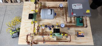
I'm finally getting ready to solder/install my heating panel, but would love any obvious tips/feedback/errors in my setup.
I used menards/sioux/radient tech for much of my planning, as well as forum searching and lots of reading. I'm to the point of soldering together my own panel, having sourced my own components, to Mimic the panel below (couldn't bring myself to spend $2000 on something I could build for $500) May bite me, but we'll see!

Pad is 4 inches thick, with 2 inches of high density foam board under it, and beside it. w/ moisture barrier.
8, 300 Foot loops, following the recommended pattern from vendor diagram. Pressure checked. in fact still have air in it. no leaks.

My panel is to mimic this 1-Zone panel. Besides being more compact, I think I did ok.


I was recommended a 19KW boiler (electric is my only option)

I already see I need to flip my manifold bleeder valves, with my inlets (left to right), to avoid jumping the hot/cold hoses from the panel to the manifolds. No biggie.
I'm about to start soldering this monster together this weekend. Would love to have some feedback before I hit the point of no return.

I have seen a few people use THESE "hot water heater hoses" to go from their panels, to their manifolds. Anyone like/dislike that idea?

THANK YOU ALL VERY MUCH!!! I'm sure I'll have wiring questions soon....


1672416332207.png1672416460190.png
 
To avoid these ads, REGISTER NOW!

fitter30

Well-known member
Joined
Jun 23, 2019
Messages
2,981
Location
Peace Valley,mo
Looks good. Why are you using Primary/ secondary loop purge tee instead of just back to back tees? Your micro bubble air eleminator will take care of all the air. Glycol if used has to be made for a boiler system minimum 30% for the inhibitor package.
 
OP
J

JohnnyMac

Well-known member
Joined
Dec 29, 2022
Messages
76
Looks good. Why are you using Primary/ secondary loop purge tee instead of just back to back tees? Your micro bubble air eleminator will take care of all the air. Glycol if used has to be made for a boiler system minimum 30% for the inhibitor package.
thank you very much for the response! I assume you're asking me about why I used this, opposed to just 2 90 degree fittings? I was simply following my plan to copy the recommended panel. Once I mocked it up, I gathered it appears to really only loop off the bottom, and that may be what it's for, but already had it. Are you suggesting I remove it and just put in 90's there? At this point it may just stay since I have it all cut and mocked up.
1672422387654.png
as for coolant/water. I purchased this cryo-tek product, and distilled water, again on their recommendation. If thats not what i should have, let me know! thanks again!!
 

TurnipTruck

Well-known member
Joined
Aug 28, 2005
Messages
1,572
Location
Southcentral Alaska
thank you very much for the response! I assume you're asking me about why I used this, opposed to just 2 90 degree fittings? I was simply following my plan to copy the recommended panel. Once I mocked it up, I gathered it appears to really only loop off the bottom, and that may be what it's for, but already had it. Are you suggesting I remove it and just put in 90's there? At this point it may just stay since I have it all cut and mocked up.
1672422387654.png
as for coolant/water. I purchased this cryo-tek product, and distilled water, again on their recommendation. If thats not what i should have, let me know! thanks again!!
This valve will ONLY be closed when initially purging the system of air, and thereafter needs to be left open. It is a fancy replacement for a pair of ”closely-spaced tees” used in primary/secondary pumping. Your pump for the boiler will inject warmed water through the closely spaced tees into the main circulating loop pumping into the floor while isolating the two different flow rates.
Look for the valve handle labeled “CRITICAL” on the example you copied.
Honestly not sure what you mean by "makeup".
How are you filling the system? Via one of the hose spigots?
Your drawing shows an anti-backflow valve and a water pressure regulator at the very top. Or are you pumping a glycol/water mix in the system? Either way, add a tee and valve.
 
Last edited:
OP
J

JohnnyMac

Well-known member
Joined
Dec 29, 2022
Messages
76
This valve will ONLY be closed when initially purging the system of air, and thereafter needs to be left open. It is a fancy replacement for a pair of ”closely-spaced tees” used in primary/secondary pumping. Your pump for the boiler will inject warmed water through the closely spaced tees into the main circulating loop pumping into the floor while isolating the two different flow rates.
Look for the valve handle labeled “CRITICAL” on the example you copied.

How are you filling the system? Via one of the hose spigots?
Your drawing shows an anti-backflow valve and a water pressure regulator at the very top. Or are you pumping a glycol/water mix in the system? Either way, add a tee and valve.

Well thank you for mentioning that, because looking at the water path flow, I would have assumed it was closed, thus isolating the 2 loops.. yikes. glad i posted this thread. I'll have to rear the instructions carefully and make sure I'm not doing anything else stupid.

I was going to fill it through the provided "entry fill" and "exit fill" and then via the pressure blow off valve if needed, as it's the high point.

Yes I posted the antifreeze they recommended above. mixed with distilled water. The picture of the vendor panel doesn't have that high T you're mentioning. I do see it on the paper diagram however... I think i copied the vendor panel picture pretty closely.

again, THANK YOU!!
 

PoorUB

Well-known member
Joined
Mar 29, 2021
Messages
11,656
Location
Fargo, ND
Looks good. I would take out the relief valve on the upper left and add a T and a water valve, hose bib, put the relief in above the T. The valve will help to purging air at the highest point. but no a big deal as the air eliminator is right there, but a valve there will move air faster than the air eliminator while filling. You can always pop the relief valve open, but some guys frown on that.

You couple do with a bit more BTU, but you are not far off. Depending on who you listen to you can go all the way to 35 BTU per foot of tubing. Where I worked we always used 30 BTU fer foot.
 
OP
J

JohnnyMac

Well-known member
Joined
Dec 29, 2022
Messages
76
Looks good. I would take out the relief valve on the upper left and add a T and a water valve, hose bib, put the relief in above the T. The valve will help to purging air at the highest point. but no a big deal as the air eliminator is right there, but a valve there will move air faster than the air eliminator while filling. You can always pop the relief valve open, but some guys frown on that.

You couple do with a bit more BTU, but you are not far off. Depending on who you listen to you can go all the way to 35 BTU per foot of tubing. Where I worked we always used 30 BTU fer foot.
Thank you for your input! so whats the point of a hose bib? just that you can fill it via Garden hose? or you treat it as a burp valve?

Are you suggesting i don't use a pressure relief valve?

My thoughts based on your comments is I add 4 inches of pipe under the pressure relief valve, and fill it via that high spot. I understand I'll need to purge plenty of air, but believe that can be done via the air separator valve, and it won't hurt anything to top off by spinning the pressure valve back off and topping off there if it burps a ton of air...no?

and agree on the BTU...I settled on 19 after getting both 19 and 24 recommendations. The wiring/amp requirements were more manageable.
 

PoorUB

Well-known member
Joined
Mar 29, 2021
Messages
11,656
Location
Fargo, ND
Thank you for your input! so whats the point of a hose bib? just that you can fill it via Garden hose? or you treat it as a burp valve?

Are you suggesting i don't use a pressure relief valve?

My thoughts based on your comments is I add 4 inches of pipe under the pressure relief valve, and fill it via that high spot. I understand I'll need to purge plenty of air, but believe that can be done via the air separator valve, and it won't hurt anything to top off by spinning the pressure valve back off and topping off there if it burps a ton of air...no?

and agree on the BTU...I settled on 19 after getting both 19 and 24 recommendations. The wiring/amp requirements were more manageable.
Reread what i said! Just T in a "burp" valve as you called it below the relief. Leave the pressure relief in the system, you need it!

You want to fill at the lowest spot so air can naturally migrate out of the system. Bleed air at the high spot.

The 19 KW is pretty close. 400 feet of tube at 30 BTU per foot comes to 72,000 BTU versus your 19KW heater putting out almost 65,000 BTU.

Where are you located? North slope of Alaska needs more BTU than northern California.
 
OP
J

JohnnyMac

Well-known member
Joined
Dec 29, 2022
Messages
76
Reread what i said! Just T in a "burp" valve as you called it below the relief. Leave the pressure relief in the system, you need it!

You want to fill at the lowest spot so air can naturally migrate out of the system. Bleed air at the high spot.

The 19 KW is pretty close. 400 feet of tube at 30 BTU per foot comes to 72,000 BTU versus your 19KW heater putting out almost 65,000 BTU.

Where are you located? North slope of Alaska needs more BTU than northern California.
Ohio. I understand bleed vs fill. Thank you.
 

Sumboodie

Well-known member
Joined
Mar 20, 2021
Messages
10,700
Location
AK
thank you very much for the response! I assume you're asking me about why I used this, opposed to just 2 90 degree fittings? I was simply following my plan to copy the recommended panel. Once I mocked it up, I gathered it appears to really only loop off the bottom, and that may be what it's for, but already had it. Are you suggesting I remove it and just put in 90's there? At this point it may just stay since I have it all cut and mocked up.
1672422387654.png
as for coolant/water. I purchased this cryo-tek product, and distilled water, again on their recommendation. If thats not what i should have, let me know! thanks again!!
You don't add water to that, it's already mixed. Unless you got the concentrate. The one is the link is 55%.

We normally sell 60% TriaFrost at work, 50% isn't rated quite cold enough.
I forget the min temps off hand. I do know the rated temps are under ideal conditions with fresh stuff.
IE... don't cut it close to the #s.
 
Last edited:
OP
J

JohnnyMac

Well-known member
Joined
Dec 29, 2022
Messages
76
You don't add water to that, it's already mixed. Unless you got the concentrate. The one is the link is 55%.

We normally sell 60% TriaFrost at work, 50% isn't rated quite cold enough.
I forget the min temps off hand. I do know the rated temps are under ideal conditions with fresh stuff.
IE... don't cut it close to the #s.
Reading the instructions, even though it's 55% as it comes, it is to be diluted with distilled water for desired temperature coverage. Radiant tech told me to use this, with water....are they incorrect?

 
To avoid these ads, REGISTER NOW!
OP
J

JohnnyMac

Well-known member
Joined
Dec 29, 2022
Messages
76
Are the pumps supposed to be fighting each other between the tee's?
Seem like the secondary pump should be pumping in the other direction.
The paper diagram, and the panel picture/instructions show them pointing the same direction. I'm still wrapping my head around that also, but I think I have it correct?
 
OP
J

JohnnyMac

Well-known member
Joined
Dec 29, 2022
Messages
76
Can't do a simple fill with a glycol system. Need a reservoir tank and pump.

I have an electric transfer pump. I suppose that's why guys above said plumb a hose bib into it....to attach a washing machine hose to and force feed it?

Can't I do that through those valves on the manifolds?
 
Last edited:

Kezorm

Well-known member
Joined
Aug 18, 2021
Messages
174
Location
Twin Cities, MN
The paper diagram, and the panel picture/instructions show them pointing the same direction. I'm still wrapping my head around that also, but I think I have it correct?
Assuming you have them pumping as shown on plan, they are correct. This is classic primary / secondary configuration. You essentially have 2 independent loops. The valve connecting the 2 loops needs to be open in operation. The floor loop just "steals" hot water away from the system loop in operation. Research something like 'hydronic primary / secondary".
 

86turbodsl

Well-known member
Joined
Jul 1, 2005
Messages
6,558
Location
Michigan
What are you using for controls? Just an air thermostat on/off deal? Consider outdoor reset unless you like swings, or you have VERY good insulation.
 
OP
J

JohnnyMac

Well-known member
Joined
Dec 29, 2022
Messages
76
What are you using for controls? Just an air thermostat on/off deal? Consider outdoor reset unless you like swings, or you have VERY good insulation.
Yes the orange box is a thermostat. Didn't even know what an outdoor reset was until I just Googled it. Interesting
 

86turbodsl

Well-known member
Joined
Jul 1, 2005
Messages
6,558
Location
Michigan
I found high mass emitters like slabs are hard to regulate without reset. But i suppose it depends on what you can tolerate.
 
OP
J

JohnnyMac

Well-known member
Joined
Dec 29, 2022
Messages
76
Anyone have an opinion on If flex water heater supply hoses would be a bad idea when it comes to mating the panel to manifolds? Would sure uncomplicated the last few solder connections...thx
 

TurnipTruck

Well-known member
Joined
Aug 28, 2005
Messages
1,572
Location
Southcentral Alaska
Anyone have an opinion on If flex water heater supply hoses would be a bad idea when it comes to mating the panel to manifolds? Would sure uncomplicated the last few solder connections...thx
Only if you plan on changing the flex every 5 to 7 years, like washing machine hoses. Which reminds me, I’m overdue.
 

Firebrick43

Well-known member
Joined
May 12, 2015
Messages
14,101
Location
West central Indiana
Anyone have an opinion on If flex water heater supply hoses would be a bad idea when it comes to mating the panel to manifolds? Would sure uncomplicated the last few solder connections...thx
No, its as simple as that, No.

At least you used unions below the boiler, make sure you leave plenty of room above the boiler.
 
OP
J

JohnnyMac

Well-known member
Joined
Dec 29, 2022
Messages
76
After solder, I am bench pressure checking my panel before hanging it, or permanently attaching to the board. Lucky I did! My solders had ZERO issues. But had one of my swivel joints, the plastic strainer, and two npt threaded Teflon pasted joints leaking. Was really surprised on the Teflon pasted npt joints having issues! I damn near swore off tape forever...glad I kept a roll.
 

Attachments

  • 20230102_193747.jpg
    20230102_193747.jpg
    602 KB · Views: 74

fitter30

Well-known member
Joined
Jun 23, 2019
Messages
2,981
Location
Peace Valley,mo
Thank you for your input! so whats the point of a hose bib? just that you can fill it via Garden hose? or you treat it as a burp valve?

Are you suggesting i don't use a pressure relief valve?

My thoughts based on your comments is I add 4 inches of pipe under the pressure relief valve, and fill it via that high spot. I understand I'll need to purge plenty of air, but believe that can be done via the air separator valve, and it won't hurt anything to top off by spinning the pressure valve back off and topping off there if it burps a ton of air...no?

and agree on the BTU...I settled on 19 after getting both 19 and 24 recommendations. The wiring/amp requirements were more manageable.
So u can use a washing machine hose because of 2 female ends
 
OP
J

JohnnyMac

Well-known member
Joined
Dec 29, 2022
Messages
76
So u can use a washing machine hose because of 2 female ends
Yeah I have those male fittings on 4 other locations for fill/recirc. Both on the manifolds and by the upper motor.

Thanks for the explanation.
 
OP
J

JohnnyMac

Well-known member
Joined
Dec 29, 2022
Messages
76
Can I ask for some wiring clarification help please for this Taco sr501-4 relay.

I'm gathering from the instructions that I would have to use the alternative wiring diagram since I have 2 pumps. That correct so far?

I need to add a resistor between the W and 24 vac terminals?

The relay gets 12v power via N, which also goes to the circulator pump

Thermostat goes to R/W TT.


What is H? I have a factory jumper there...remove??

My largest confusion comes as to where the other pump wires in...? Terminal 5, 4, ZC, and ZR, have me confused. I'm not gathering where the 2nd pump ties in.
 

Attachments

  • 16730959361431186272689329253840.jpg
    16730959361431186272689329253840.jpg
    1.3 MB · Views: 48
  • 16730959523352817768995595801773.jpg
    16730959523352817768995595801773.jpg
    873.1 KB · Views: 31
  • 16730959695873585980351938360479.jpg
    16730959695873585980351938360479.jpg
    799.8 KB · Views: 31

TurnipTruck

Well-known member
Joined
Aug 28, 2005
Messages
1,572
Location
Southcentral Alaska
I have never done an electric boiler, but I strongly suspect that the boiler itself controls its circulation pump, and the zone pump will be controlled by your relay when the thermostat tells it. Then terminals 5,6 are wired to ”TT” on the boiler.

So the normal sequence should be:
1) thermostat gets cold, calls for heat.
2)relay turns ON, activating the zone pump.
3)boiler sees that the relay wants some heat via TT closing.
4)boiler turns its own pump on and it’s internal flow switch then sees flow.
5) all permissives are satisfied? Then big contractor turns on the heating elements.

Use the typical (left) schematic.
 
OP
J

JohnnyMac

Well-known member
Joined
Dec 29, 2022
Messages
76
2748C92F-D71F-42BA-B9A6-5A628F35493C.png
Nope, my assumptions were wrong in the prior post. This schematic is what you need to use.
THANK YOU SO MUCH!!!! where did you find that?? It's not in any of my instructions, and I googled like mad yesterday!
 

TurnipTruck

Well-known member
Joined
Aug 28, 2005
Messages
1,572
Location
Southcentral Alaska
I don’t see anything from the thermostat or the switching relay to trigger the boiler to turn on, so I’m presuming that once the boiler circulator pump turns on and causes flow, the boiler flow switch then turns on the heat?
I guess that is the safest way.
 
To avoid these ads, REGISTER NOW!
Top Bottom