To avoid these ads, REGISTER NOW!

My Wilton C2

OP
A

alan camby

Well-known member
Joined
Dec 3, 2011
Messages
1,566
Location
South of Indianapolis, Indiana
Alan: since you are making an already great vise better you might want to thread those double pins that hold the vise nut in like a few members have done. It would make cleanings and re greasing the vise easier in the future. i can't remember the vise repair 101 post # where the members talk about it, but with your skills just mentioning it's a possibility is probably enough.

one of my clients that used to fabricate and work on hydros had his brand new Wilton bullet vise sandblasted and he left it naked because he didn't want any paint around his welding table. i think it looks pretty good naked, but your vise and your color is the rule.

good luck and looking good so far.

BTW

drive,
Thanks for the idea. I like it. I like it enough I put the tail casting on and slid the nut in and stared at it for 10 min. I really did not like the idea of having three items all threaded together on each side. I noticed how the main casting and the end casting fit very tight together. Did not like how the nut has a gap between the end casting and nut, on the side.

My plan is to tap the main and tail casting while mounted together. I will use 5/16-18 set screws. The end of the screws will look like a dog point set screw. I looked at using standard dog points but the diameter of the dog is to small. So I will add my own custom dog point to the set screws. While installing the set screw, I will not apply pressure to the nut, just engage my 1/4" diameter dog in the nut. A drop of blue Loctite will keep the set screw from backing out.
1/4" is the diameter of the factory pins.

If I want to remove the nut. All I need to do is back out the set screws.

The sided of the vise will stay clean, no exposed bolt heads.

As far as the raw look. I like the look of raw steel, but I think the texture of media blasted metal is not my thing. Also the feel reminds me of a chalkboard.
My vise will be painted.

Thanks much.
 
Last edited:
To avoid these ads, REGISTER NOW!
OP
A

alan camby

Well-known member
Joined
Dec 3, 2011
Messages
1,566
Location
South of Indianapolis, Indiana
Hey Alan
Nice work on your end cap, it would be way to much work for me to start making endcaps for the bullets, here is one I made for a baby I am trying to find time finishing up. I do not own a lathe so I have to make mine on a CNC, as you can see I step off the radius and attach it to a threaded rod so I can chuck it in my wood lathe where I file it to remove the steps. I added a step to the end cap, I like how it came out. There is no reason to make these as thin as the originals as long as the center hole is clearanced for the spindle. Some day I will have room for a lathe and it would drastically change the way I make vise parts. Great job on your restoration and enjoy your post.

KM Scott,
your baby looks great and has the stock look. Thanks for all the information and Kudos.
 
OP
A

alan camby

Well-known member
Joined
Dec 3, 2011
Messages
1,566
Location
South of Indianapolis, Indiana
Lots of fun today.


Sandblasted w/ fine grit coal slag. The inner ring was only sprayed with primer.
https://scontent-b-dfw.**.fbcdn.net/hphotos-xap1/v/t1.0-9/10416567_626149840850278_1636726596148878872_n.jpg?oh=b4fb6a0ea86a4fd8070bf6b731e017d7&oe=55651204

sandblasted. Think the C2 excels at the rings. He has been holding this position for hours.
https://scontent-b-dfw.**.fbcdn.net/hphotos-xpa1/v/t1.0-9/10947281_626149814183614_507653764089374282_n.jpg?oh=37d3c10ec09c86cc4192416433aa7ea6&oe=556D534F


Red oxide primer. Did 3 coats.
10931281_626149777516951_4434420139641939264_n.jpg


Little brother holding up the C2 to dry. C2 was not painted around the Parker.
Think my finger might have made the picture.

If you are wondering, there is a square tube in the Parker jaws. The Wilton is slid over the square. There was no use of the force to hold him vertical.
https://scontent-a-dfw.**.fbcdn.net/hphotos-xpf1/v/t1.0-9/10945763_626149747516954_8531425996977715316_n.jpg?oh=a529cfac56587519d39667b21fd7adb2&oe=5524CDB7

Three coats of Pepsi blue. pictures don't show a good representation of the color. Take a Pepsi out of the fridge and that is the color.
10352084_626149710850291_8627563838294350100_n.jpg


Yes I painted the anvil. Hope this might discourage others from thinking it is a anvil.


Here are a few more that show the color better.
https://scontent-b-dfw.**.fbcdn.net/hphotos-xpf1/v/t1.0-9/10428415_626257010839561_2697805237157572282_n.jpg?oh=2389beb372e488dc79c2091dd5ac113a&oe=5528F966

1461342_626257050839557_706639049591351186_n.jpg
 
Last edited:
OP
A

alan camby

Well-known member
Joined
Dec 3, 2011
Messages
1,566
Location
South of Indianapolis, Indiana
Here are the pins for the main nut.

Modified with a 1/4" tip compared to a stock 5/16-18x1-1/2" set screw.
https://scontent-b-dfw.**.fbcdn.net/hphotos-xpf1/v/t1.0-9/10945768_627149507416978_2708608823685162625_n.jpg?oh=d4aac2ee45ea2bb9e7d7989de5042a20&oe=55517C6E

Vise is almost done. Still need to clean and install pipe jaws.
1014052_627149440750318_3403357645631038434_n.jpg


It is so much easier to put the base on with the help of a shop crane. Outer and inner ring has 3 coats of primer. I did not paint the underside in order to keep the thicker paint out of the lockdown teeth.
https://scontent-b-dfw.**.fbcdn.net/hphotos-xpa1/v/t1.0-9/10933840_627149480750314_3378007769083390228_n.jpg?oh=01f018c30698c6301413d1682685a32c&oe=5555029A

Next I will be building a vise stand.

Thanks for checking it out.
 
Last edited:

drivesitfar

Well-known member
Joined
Oct 23, 2013
Messages
36,040
Location
Pacific Northwest
Alan: are you hanging the vise by those washers you welded a bolt to from your shop crane when you painted it? nice work and thanks for the pictures. your Wilton C2 doing an iron cross description needed a picture so hopefully it's ok to post this one.

did you tap the original holes for the pins to hold the vise nut with a 5/16 tap? then taking the threads off the end of the set screws to hold the vise nut in did you use a bench grinder or do tell how you removed them?

very nice vise and a terrific restoration.
 

Attachments

  • yuri-van-gelder-l-cross-on-rings.jpg
    yuri-van-gelder-l-cross-on-rings.jpg
    46.4 KB · Views: 15
OP
A

alan camby

Well-known member
Joined
Dec 3, 2011
Messages
1,566
Location
South of Indianapolis, Indiana
Alan: are you hanging the vise by those washers you welded a bolt to from your shop crane when you painted it? nice work and thanks for the pictures. your Wilton C2 doing an iron cross description needed a picture so hopefully it's ok to post this one.

did you tap the original holes for the pins to hold the vise nut with a 5/16 tap? then taking the threads off the end of the set screws to hold the vise nut in did you use a bench grinder or do tell how you removed them?

very nice vise and a terrific restoration.

Drive,
The vise was hanging from the garage door rails. Your picture is what I was thinking too.

Yes I tapped the original holes. The factory holes are close to, if not, 1/4" diameter. The proper hole size for 5/16-18 is .257", which is a "F" drill bit.

If you do this the way I did. Do not drill the main nut that is for the spindle. The nut will retain the factory 1/4" hole.

First I installed the rear cast housing in the main vise housing. I spent some time making sure the holes from both housing aligned as close as possible. Next I drilled the factory holes with the F drill bit.

I always put a small chamfer on a hole that I am going to tap. I use a drill bit looking thing called a countersink that has a 82 degree angle. The angle is not that important for this, 82 degrees happens to be the angle of USS/SAE flat head screws. BTW Metric Flat head screws have a 90 degree angle. The purpose of the countersink when tapping is to help start the tap and it leaves a nice surface when finished. Without the counter sink a small bur might be present, on the surface of the metal, where the thread starts into the material tapped.

On deep through hole tapping, I like to use a blowgun with a small tip to blow the chips out as I go. I blow the chips out in the flute area of the tap.


When placing the nut down into the vise, it is important that it is installed the right way. Obviously the threaded end goes in first. Where a person could really go wrong is aligning the nut holes with the side holes in the vise. It is very important to look thru the holes in the side of the vise and make sure they are in near perfect alignment with the nut holes. If it looks off at all, pull the nut and rotate it 180 degrees and reinstall. Check the rotated nut and see if it aligns better. Failure to do this could mean cracking the nut when installing the set screws or the factory dowel pins.

As far as the thread removal on the 5/16-18 set screws. I used my lathe to remove them down to .250"

Thanks, Alan
 
Last edited:
OP
A

alan camby

Well-known member
Joined
Dec 3, 2011
Messages
1,566
Location
South of Indianapolis, Indiana
In hindsight, the best , and easiest way to have removable pins is probably a pull style dowel pin.

the factory pin on my vise is 1/4". They make pull style down pins that are internally threaded. The 1/4" size has a 8-32 internal thread that a screw can be inserted in. Using a slide hammer or other means of pulling, the pin can be pulled back out.

These pins would allow a person to have removable pins without modifying the vise. If I take apart my 500 or 1755 wilton's, I will probably go back together with these instead.

the threaded hole in the pin could be capped with a screw or set screw to keep dirt out of the threads.
 
OP
A

alan camby

Well-known member
Joined
Dec 3, 2011
Messages
1,566
Location
South of Indianapolis, Indiana
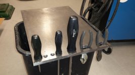
I have started on my stand for the c2.
I found a piece of scrap 12" x 18" x 1/2" cold rolled plate.

I decided to make half of it the base for the vise and the other half will be a small platform to put stuff on while working with the vise. I used my mill to square off one of the edges and decided to drill some holes and put In a few slots.

Now I need to decide if I want the platform on the right or the left of the vise.
What do you guys think? I am right handed. The pictures show the platform portion on the right but I can easily flip it over. Need to make a decision today or tomorrow at the latest because I will be working on the vertical support very soon.
 

Attachments

  • uploadfromtaptalk1422558188814.jpg
    uploadfromtaptalk1422558188814.jpg
    135.4 KB · Views: 25
OP
A

alan camby

Well-known member
Joined
Dec 3, 2011
Messages
1,566
Location
South of Indianapolis, Indiana
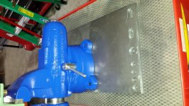
Sorry I think this is going to post sideways. No matter how I rotate the picture in my phone, tapatalk shows it sidways.

Anyhow, here is where the vise goes in relationship to the work platform. Obviously I could flip it over and have it on the left.

Any thoughts?
 

Attachments

  • uploadfromtaptalk1422558364888.jpg
    uploadfromtaptalk1422558364888.jpg
    151.4 KB · Views: 42

drivesitfar

Well-known member
Joined
Oct 23, 2013
Messages
36,040
Location
Pacific Northwest
Alan: since you are going to have tools on the platform and you are right handed wouldn't right make sense? personally i'd probably put the tools on the vertical support and have the extra room on the platform for projects.

i'm sure it will be ok either way and with the quality of work you do the stand and the vise will be another great picture for all of us to admire.

good luck
 
To avoid these ads, REGISTER NOW!
OP
A

alan camby

Well-known member
Joined
Dec 3, 2011
Messages
1,566
Location
South of Indianapolis, Indiana
Thanks guys,
I was thinking the platform would be best on the right. Seems like a while back I read, onGJ, that a vise, for a right paw, should go on the right side of the bench. So was kind of second guessing by having the vise on the left side of the platform.

Drive,
I don't really plan to store tools on the slots. It will be more of a place to set one down if I have it out.
Just like my 500N mount has the tool holes in the mounting plate. I hardly use them but sometimes they come in handy.

I am thinking of a way to keep spare vise jaws in a pocket/shelf on the column.
My plan is to use soft jaws and store the factory toothed jaws.
 

oldldh

Well-known member
Joined
May 22, 2012
Messages
3,700
Location
Fairhope, AL
Fixed it for you...

As a fellow righty...

I'd leave it like that...

Your vise is a "Swivlin' B@#tard"...:sad:

I won't matter which side you put it one....:spit:

It rotates!!!:evil:
 

Attachments

  • c2blue.jpg
    c2blue.jpg
    124 KB · Views: 38
OP
A

alan camby

Well-known member
Joined
Dec 3, 2011
Messages
1,566
Location
South of Indianapolis, Indiana
Thanks Everyone for the comments.

Gert,
I remember your C2, always thought it was orange. I just looked thru your posts and found your C2 thread and never would have guessed it was red. Looks real good :thumbup:.

I was really tempted to go Allis Chalmers Orange but was out of that color and had 3 cans of Pepsi Blue.
 

CNGsaves

Well-known member
Joined
Sep 26, 2012
Messages
13,233
Location
KS and OK
^ ^ ^ Great result . . . . superb !!! :thumbup:

NOT complete though . . . . haven't seen PIC with a Pepsi can for comparison ! ;)

Let's see few MORE PIC's that have some Pepsi cans !!! :D
 
OP
A

alan camby

Well-known member
Joined
Dec 3, 2011
Messages
1,566
Location
South of Indianapolis, Indiana
Started on the base of the base :headscrat

Step one, Find a bunch of stuff to build it with. I was out of PVC and popsicle sticks so this is what I came up with.

-Metric c-channel that is roughly 3"x6" with a center thickness just shy of 3/8" thick. This piece is 14" long.
-4" schedule 40 black pipe. This has a OD of 4.5" and a .237" wall thickness.
I cut this to 30.5" long
-3"x3"x3/8" angle steel. Two pieces 12" long.

10898041_628477677284161_174960942765630634_n.jpg


next I cut 45 degree ends on the angle. Sandblast all the red paint off of the c-channel, and mill scale off of angle. Drilled four 5/8" holes that will be the anchor holes.

Here is me reaming the 7/16" holes to 5/8"
1903997_628477697284159_1438818634900299595_n.jpg


Here are the pieces ready for welding. Notice the 5/16" keystock that is used as a spacer for the c-channel. Hard to tell in the picture but 2" of the angle protrudes from the front of the stand and about 4 inches protrude from the rear. The idea is to get most of the trip hazard to the backside.
10462675_628477727284156_5556019520126716035_n.jpg


Hers is the angle and c-channel welded together. I cleaned up all the spatter with a 4.5" wire wheel. The pipe is just there for looking at.
10968548_628477660617496_2769899111394488667_n.jpg


That was pretty much it for the night.
I stacked everything to get a idea of the finished product. The pipe will be welded to the base but the top of the pipe will bolt to the vise plate.
https://scontent-b-dfw.**.fbcdn.net/hphotos-xpf1/v/t1.0-9/10013127_628540497277879_3479805533592324773_n.jpg?oh=226b84d38dd63a35d6cba640855c2ac4&oe=55565130
 
OP
A

alan camby

Well-known member
Joined
Dec 3, 2011
Messages
1,566
Location
South of Indianapolis, Indiana
Test fitting the Wilton to his new home.

https://scontent-b-dfw.**.fbcdn.net/hphotos-xpf1/v/t1.0-9/10260014_630618097070119_1832165160542532013_n.jpg?oh=7186f6748577f5117de86be1d962c6af&oe=5559809A


https://scontent-a-dfw.**.fbcdn.net/hphotos-xpf1/v/t1.0-9/10953970_630618043736791_7682439095040406313_n.jpg?oh=a371ac15f6e634c41790b0b8f4a222ec&oe=55497EBB

Still need to add a shelf or two under the platform.
Than paint the stand black.
 

blind

Well-known member
Joined
Oct 24, 2010
Messages
217
Location
KY
I hate to see it in your shop and not mine but atleast you've taken care of it and painted it UK blue. I had to work the weekend you picked it up and saw your post in the vise thread. I immediately knew it was the one.
 
Last edited:
OP
A

alan camby

Well-known member
Joined
Dec 3, 2011
Messages
1,566
Location
South of Indianapolis, Indiana
Added two small shelves to hold a pencil, sharpe, spare jaws and other ect.

Finished painting the stand today and it is hanging in my shop to dry.

https://scontent-a-dfw.**.fbcdn.net/hphotos-xfa1/v/t1.0-9/p480x480/10444361_632337413564854_5882662804540175983_n.jpg?oh=2067e51e2e39a4556e923428b00650a3&oe=55645DF9

https://scontent-a-dfw.**.fbcdn.net/hphotos-xfp1/v/t1.0-9/10952583_632337506898178_5970423221903201270_n.jpg?oh=2ce324b500bf94df7e5e1287fa5643ca&oe=554DB1A4
 
OP
A

alan camby

Well-known member
Joined
Dec 3, 2011
Messages
1,566
Location
South of Indianapolis, Indiana
Sanded all the edges on my steel top and installed.
https://scontent-b-dfw.**.fbcdn.net/hphotos-xpa1/v/t1.0-9/10686678_632503976881531_7646382576485832996_n.jpg?oh=4ff617211292b3d1235f89ef22dcdadb&oe=5549588B

10603511_632503936881535_795931557030609730_n.jpg


Think I am finally done.
https://scontent-a-dfw.**.fbcdn.net/hphotos-xaf1/v/t1.0-9/10448819_632503906881538_351183220465626652_n.jpg?oh=a95a7f59c1a8c381305b09a8f524d240&oe=5562BC29

10959403_632508006881128_2568000841143542695_n.jpg
 

drivesitfar

Well-known member
Joined
Oct 23, 2013
Messages
36,040
Location
Pacific Northwest
Alan: I'm going to save the pictures of your C2 and stand to my laptop. very nice work. i see you bolted the stand to the floor so it's found a permanent home. i also see you tapped the steel plate and screwed it on from down below. what i don't understand is what that bolt going down is for that would be sitting under your Wilton?

thanks again for sharing your tips, tricks and pictures of your restoration and stand build. :thumbup::thumbup:
 
OP
A

alan camby

Well-known member
Joined
Dec 3, 2011
Messages
1,566
Location
South of Indianapolis, Indiana
Alan: I'm going to save the pictures of your C2 and stand to my laptop. very nice work. i see you bolted the stand to the floor so it's found a permanent home. i also see you tapped the steel plate and screwed it on from down below. what i don't understand is what that bolt going down is for that would be sitting under your Wilton?

thanks again for sharing your tips, tricks and pictures of your restoration and stand build. :thumbup::thumbup:

Thanks for all the comments.
The 5th bolt is just one that is installed opposite of the other 4.
Instead of the bolt coming up from the bottom and threading into the plate this bolt goes thru a though hole and threads into the column.

All of the bolts are using a small .5" ID x 1" OD x 2.25" long DOM tube welded to the column to make the connection point. The back tube was bored to
17/32" diameter on the lathe and threaded 5/8-11. I added it for extra support and for the fun of it. There is plenty of room under the swivel base of the vise to accommodate the 15/16" hex head of this bolt head. All these bolts are made in Indiana. The 5/8-11x2" is a Nucor (stamped lower case n) grade 5. The other 4 are 7/16-14x3" Lake Erie (stamped LE) grade 8.

All 5 DOM tubes were welded to the column while the column was upside down and the column was held vertical. Than the column was placed on the top plate upside down. Used transfer punches to make the bolt pattern on the top plate.

Most would probably weld the top to the column. The heat required to do this makes it almost impossible to do without distorting the top plate. I am not proficient at flame straitening and just preferred the idea of keeping the heat off of this plate. The cold rolled top is pretty nice compared to hot rolled when it comes to finish and flatness.

BTW. The four 5/8-11x3" bolts that fasten the swivel base to the top are flange bolts. The casting for the swivel base has almost no clearance for a washer or for the flange bolt. The bolts were ground flat on the one side that is closest to the vise. The bolts now look more like a D-shaped bolt when looked at from the end.
 
Last edited:
To avoid these ads, REGISTER NOW!
Top Bottom