To avoid these ads, REGISTER NOW!

Need Help with Converted Bandsaw wiring/identification/explanation please

Hephaestus29

Well-known member
Joined
Mar 13, 2011
Messages
2,989
Location
Indianapolis
Thanks in advance. My Electrical knowledge is mostly basic but I can follow some things but need help understanding what's going on here.

The Bandsaw is a DoAll 16-2 with a blade welder/grinder.

I'm not sure the motor is original, and was thinking it was three phase by looking at the plug end. But after closer inspection I see the black wire was not hooked up at either end of the cord.
I removed the plate on the motor and I don't know but i'm guessing it's
single phase 220 ???

It does mention 220 volts in the manual for my model, but I'm finding the manual hard to follow, it seems like it's not laid out very well to me.

I'm guessing if I switch the plug end to a 3 prong style Stove end I can use it on my already existing welder plug.

Also notice the jumpers on the fuses, can you tell me about that ? Thanks
 

Attachments

  • IMG_2384.jpg
    IMG_2384.jpg
    141.3 KB · Views: 88
  • IMG_7068.jpg
    IMG_7068.jpg
    140.2 KB · Views: 64
  • IMG_9366.jpg
    IMG_9366.jpg
    131.7 KB · Views: 68
  • IMG_9440.jpg
    IMG_9440.jpg
    138.1 KB · Views: 59
To avoid these ads, REGISTER NOW!

wyliesdiesels

Well-known member
Joined
Aug 14, 2012
Messages
20,073
Location
Modesto, CA
Thats a single phase motor. It has a capacitor.

Does the motor have a label?

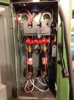
Whats with the red wires jumpering the line and load terminals in the fused disconnect?

Its a 3 phase disconnect BTW, but only 2 terminals are obviously being used...
 
OP
H

Hephaestus29

Well-known member
Joined
Mar 13, 2011
Messages
2,989
Location
Indianapolis
Motor is missing a label due to repaint
I believe.
I'm curious about the jumpers myself
other than the fuses being blown, or
at least they are rattling when I shake
them.
Load terminals in the fused disconnect ?
 

wyliesdiesels

Well-known member
Joined
Aug 14, 2012
Messages
20,073
Location
Modesto, CA
Line terminals are on the top, load terminals are on the bottom.

U should remove the jumpers. Thats dangerous and stupid. Defeats the purpose of the fuses...

Do u have a multimeter to test the fuses?

Do the motor leads have any number tags on them?

How many leads?

U could ohm them out to figure out which ones belong to each winding...
 
Last edited:
OP
H

Hephaestus29

Well-known member
Joined
Mar 13, 2011
Messages
2,989
Location
Indianapolis
Yes I have a multimeter.

There are 6 leads coming out of the motor.

Yes I figure the fuses are blown and they
didn't want to pay to replace them.

They didn't have any at Lowes, I'm
guessing they are around 20 dollars a
piece from the others I saw though.

The motor leads do have some writing
on them but I'm totally unfamiliar with
what one would look for.

Some of it is as follows:
CL 1251 X link
ULI AWM
E- 42607 SX- PA
 
OP
H

Hephaestus29

Well-known member
Joined
Mar 13, 2011
Messages
2,989
Location
Indianapolis
I put a new end on the cord, same as
a stove plug, plugged it in and turned
it on. It makes a pretty good humm
but the motor doesn't turn.
 
OP
H

Hephaestus29

Well-known member
Joined
Mar 13, 2011
Messages
2,989
Location
Indianapolis
Well I pulled the capacitor out and it says
110/125 VAC
Baldor motor
01300
860-950 MFD
USA
8016
 

Attachments

  • image.jpg
    image.jpg
    135.2 KB · Views: 19

G_P

Well-known member
Joined
Jul 11, 2010
Messages
7,135
Location
Central CT
Remove the belt, Flip the power on, then spin the motor by hand. If the motor starts and gets up to speed, the capacitor is bad.
 

Norcal

Well-known member
Joined
Mar 16, 2008
Messages
13,769
I put a new end on the cord, same as
a stove plug, plugged it in and turned
it on. It makes a pretty good humm
but the motor doesn't turn.

A "stove plug" is not proper except for a range. Not a grounding plug, they are a dual voltage device, but people use them 'cause they are cheap.

Check Baldors website, or WEG's has a bunch of wiring diagrams of a lot of different motors.
 
OP
H

Hephaestus29

Well-known member
Joined
Mar 13, 2011
Messages
2,989
Location
Indianapolis
Is the cap bulged at all?

Have u tested the fuses?

Yes I tested the fuses, they are both bad.

The capacitor does not have any bulging, but there is some residue that I've never see before
on a capacitor. It's off white and on the inside rim of the capacitor at the bottom where it was laying on it's side.
 
Last edited:

wyliesdiesels

Well-known member
Joined
Aug 14, 2012
Messages
20,073
Location
Modesto, CA
Wow. So someone stuffed a jumper in the fuse clips because they were too lazy or cheap to buy replacements?

What is the NEMA number of the outlet and plug youre using?
 
OP
H

Hephaestus29

Well-known member
Joined
Mar 13, 2011
Messages
2,989
Location
Indianapolis
A "stove plug" is not proper except for a range. Not a grounding plug, they are a dual voltage device, but people use them 'cause they are cheap.

Check Baldors website, or WEG's has a bunch of wiring diagrams of a lot of different motors.
15.00 is not cheap in my opinion and it has a place for the red, black & green wire.
 
OP
H

Hephaestus29

Well-known member
Joined
Mar 13, 2011
Messages
2,989
Location
Indianapolis
Wow. So someone stuffed a jumper in the fuse clips because they were too lazy or cheap to buy replacements?

What is the NEMA number of the outlet and plug youre using?

Yeah apparently, but after looking at fuses at Lowes I could see why. They didn't have mine but had some approximately the same length that were around 17.00.

My dad suggested since it was a 110 motor to get a different fuse box/disconnect switch with a lower amp fuse since those 600 amp would be way overkill for 110.

I'm still cornfused as to why the cord had the 4 pronged 3 phase plug unless they had an adapter to go from the 4 prong to a 3 prong 110 ???

I don't know about the Nema # I'll have to get back on that one. That is going to change anyway since it's a 220 plug and the motor is a 110. I'll have to find a big 110 plug big enough for that big 4 wire cable or switch to 3 wire cable.
 
Last edited:

wyliesdiesels

Well-known member
Joined
Aug 14, 2012
Messages
20,073
Location
Modesto, CA
The range receptacle is NOT grounded and shouldnt be used for this application.

Yes those fuses are overkill for this application. Those are 600v rated fuses.

Switch the disconnect and u can use cheaper fuses.

This is obviously hacked together.

How are u sure that its a 115v rated motor? It could be dual voltage. And if it is 115v, did u hook it up to 240v?
 
Last edited:

Norcal

Well-known member
Joined
Mar 16, 2008
Messages
13,769
Yeah apparently, but after looking at fuses at Lowes I could see why. They didn't have mine but had some approximately the same length that were around 17.00.

My dad suggested since it was a 110 motor to get a different fuse box/disconnect switch with a lower amp fuse since those 600 amp would be way overkill for 110.

I'm still cornfused as to why the cord had the 4 pronged 3 phase plug unless they had an adapter to go from the 4 prong to a 3 prong 110 ???

I don't know about the Nema # I'll have to get back on that one. That is going to change anyway since it's a 220 plug and the motor is a 110. I'll have to find a big 110 plug big enough for that big 4 wire cable or switch to 3 wire cable.

It's a 600 volt switch, not ampere, and there is no such thing as 110, or 220 in the US anymore.

As to the 4-wire plug, you have never fully informed us as to the rating, it could be a single phase 125/250 volt rated or a 3 phase 250 volt, but just by the kludge shown one cannot trust ANYTHING on a used machine, this really applies to any machine bought used , after it's all done you will have a nice machine.
 
OP
H

Hephaestus29

Well-known member
Joined
Mar 13, 2011
Messages
2,989
Location
Indianapolis
Well regardless of what I do or don't know, I guess I need to call in an electrician to help me with this one.

I got the 3 phase mill/VFD wired up without much problem but this one uhh ??
 

MTW

Well-known member
Joined
Aug 6, 2013
Messages
294
Location
SE Michigan
A few pointers.
Before doing anything else, like trying to connect power, you must determine what voltage the motor windings are connected for 120 or 240V. Energizing with the wrong voltage will cause more problems than you currently have.

The winding leads do have numbers on them, your just not looking close enough. The printing you quoted earlier is the wire type. Turn the wires over and find the numbers. The photo you uploaded shows the number for lead #1, usually the numbers have an underline beneath them, to show the bottom of the figure so 6 & 9 don't get confused.

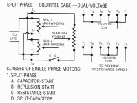
Here's a generic diagram that shows standard lead numbers . Before you disconnect any of them, you must first determine if they are connected for low or high volt operation.

SinglePhaseDualVoltReversibleMotor.jpg

Once you determine how it's connected, you'll then know what voltage to power it with for testing.

Next thing is trying to figure out what the HP is. Baldor usually has a tag riveted to the outer shell right next to the connection box. If it's missing you should see the rivet holes where it resided. If painted over you might be able to clean the paint off. Short of that you could get close on the size by looking at the frame chart and measuring the dimensions of the shaft size and height to get close.

From here that motor looks about 3/4 to 1 HP as a guess. You need to know that to select the proper fuse size. Those FRS-5 fuses are too small for a 1Φ 3/4HP motor that's why their blown and jumperd out. 5 amp would be the correct size for a 3/4HP @ 230V 3Φ, not for single phase. 10A units would be the size to use for a 3/4HP @ 230V 1Φ, 20A units would be the correct size for a 3/4HP @ 120V. But get the connections sorted before you buy some fuses to select the correct size.

Frame Chart
FrameChartTop.jpg
FrameChartMid.jpg

For the start capacitor any leakage of the dielectric fluid is a bad sign, there is a small covered vent hole in the top of the cap, if the cover is ruptured open, the capacitor definitely needs replacement. If its leaking, it also should be replaced, even if it still functions failure is eminent.

A 6 lead 1Φ dual voltage motor is an indication that there is no thermal protector built in to protect it in case of malfunction or overheating. This means that external protection must be added to prevent burnout and fires resulting. Fuses can be used for protection, but a manual motor starter with built in overload protection and heater element is preferred.

For your testing session, remove all of the belted loads from the motor first, to troubleshoot the motor only. Once you get it running the reinstall the belts for further testing.

That should be enough to get you started down the path. Check what you find and report back.

MTW Ω
 
To avoid these ads, REGISTER NOW!

gregtwojeeps

Well-known member
Joined
Jul 30, 2013
Messages
5,096
Location
Ky
I am surprised no one has not mentioned that the motor in the pic from appearances at least, looks to be the wrong type for its application. It does not look kosher to be using a open type vented motor... sitting at the base of a grinding/sawing type machine. True or false ?
 
OP
H

Hephaestus29

Well-known member
Joined
Mar 13, 2011
Messages
2,989
Location
Indianapolis
I am surprised no one has not mentioned that the motor in the pic from appearances at least, looks to be the wrong type for its application. It does not look kosher to be using a open type vented motor... sitting at the base of a grinding/sawing type machine. True or false ?

There is a large cover that goes over
everything you see on the motor side,
I just have it removed.
 

404

Well-known member
Joined
Aug 23, 2014
Messages
3,463
Location
Mass
Any capacitor that has the runs is bad.

The color choices the PO made on the plug also suggest 120 V motor. For a 240 V motor red and black would have been connected.

Remove belt as others have said.
 
OP
H

Hephaestus29

Well-known member
Joined
Mar 13, 2011
Messages
2,989
Location
Indianapolis
I went to Grainger before work to pick
up a capacitor and the first one they
bring out had been on the shelf so long
that it had been leaking.
I told him I wasn't buying that one and
he said it would be several days before
he could get another one in. I could drive
to the north side store if I had time.
I guess he thought I would take that
one, but he finally checked and they did
had another one.
 

wyliesdiesels

Well-known member
Joined
Aug 14, 2012
Messages
20,073
Location
Modesto, CA
I try to NEVER buy from grainger. Theyre way overpriced.

If youre not in a hurry to get a replacement have u thought of ordering online?
 
OP
H

Hephaestus29

Well-known member
Joined
Mar 13, 2011
Messages
2,989
Location
Indianapolis
I got the new capacitor installed after
work and it fired right up. The grinder
works but I don't know about the welder
yet, I don't have any scrap blades to
practice with, and I really don't know
how it works yet either.

I had never read any of the packages
of stove plugs but you're right they say
non-grounding. I haven't had any problems
using them before though, and I welded
with the one I have quite a bit.

The motor ended up being wired single
phase 220.
I put the jumper back in for the time
being and will have to work on getting
it switched over to a new disconnect
box later. There are a few other details
I'll have to take care of also.

Thanks to everyone for their input.
 
Last edited:

wyliesdiesels

Well-known member
Joined
Aug 14, 2012
Messages
20,073
Location
Modesto, CA
A 300v rated disconnect and fuses will be a lot cheaper.

Does the equipment need a neutral?

If so, u should switch it to a NEMA 14-** receptacle and plug.

If its 240v only then get a NEMA 6-** r and p.

The old school stove receptacles are NEMA 10-50...grounding was done through the neutral terminal...
 

404

Well-known member
Joined
Aug 23, 2014
Messages
3,463
Location
Mass
How does a 120v start capacitor survive inside a 240v motor?
 
OP
H

Hephaestus29

Well-known member
Joined
Mar 13, 2011
Messages
2,989
Location
Indianapolis
How does a 120v start capacitor survive inside a 240v motor?

I don't know, I could be wrong about
the way it's wired up but it's running
good, and I have it plugged in to
single phase 220.
The capacitor that was on the motor
had the wires soldered to it, so i'm
guessing it was original. I just replaced
it with one similar in size MFD.

I guess I need to figure it all out before
I run it much.
 

wyliesdiesels

Well-known member
Joined
Aug 14, 2012
Messages
20,073
Location
Modesto, CA
Yes but how would that work? Neutral is not connected to the motor at all.

No neutral is needed. The incoming hot leg connects to one side of the cap and the motor lead connects to the other side. The cap provides extra current and makes the supply look larger to the motor. Motors have in-rush currents that are
4x-8x FLC.

Ive replaced caps in AC units before and it was the same setup except it was a dual rated cap. One input terminal, 2 outputs- one for the compressor, one for the fan motor.
 

404

Well-known member
Joined
Aug 23, 2014
Messages
3,463
Location
Mass
No neutral is needed. The incoming hot leg connects to one side of the cap and the motor lead connects to the other side. The cap provides extra current and makes the supply look larger to the motor. Motors have in-rush currents that are
4x-8x FLC.

Ive replaced caps in AC units before and it was the same setup except it was a dual rated cap. One input terminal, 2 outputs- one for the compressor, one for the fan motor.

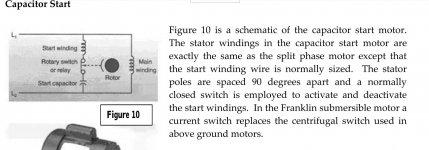
I've included a pic of a cap start motor schematic. Line 1 and 2 with 220v between them go across the cap. Even with the start winding in series, I would expect the cap to see 220 volts at some point.

The caps in the ac units are the silver metal cans right? What voltage rating do they have compared to the voltage input to the AC unit?
 

Attachments

  • capstart.jpg
    capstart.jpg
    116.1 KB · Views: 10

wyliesdiesels

Well-known member
Joined
Aug 14, 2012
Messages
20,073
Location
Modesto, CA
I've included a pic of a cap start motor schematic. Line 1 and 2 with 220v between them go across the cap. Even with the start winding in series, I would expect the cap to see 220 volts at some point.

The caps in the ac units are the silver metal cans right? What voltage rating do they have compared to the voltage input to the AC unit?

Thats incorrect. You're misinterpreting the schematic.

No where does the cap connect to both L1 and L2.

One end of the start winding is connected to L1. The other end is connected to the relay or switch.

The other end of the relay or switch is connected to one end of the cap and the other end of the cap is connected to L2.

The cap is in between L2 and the switch.

I already explained this in 33 and its the same as the diagram u posted albeit i forgot to mention the switch or relay. But the connections are the same.

Where do u see the cap connected to both L1 and L2?
 
Last edited:

MTW

Well-known member
Joined
Aug 6, 2013
Messages
294
Location
SE Michigan
How does a 120v start capacitor survive inside a 240v motor?

In a dual volt 1Φ motor the start winding and start capacitor are always connected for the low voltage 120V, in order for the winding and cap to be compatible for both voltages.

With a low voltage connection the start winding and cap are connected across the 120V supply voltage.

With high voltage connections, the start winding and cap are connected one side to line and the other to the midpoint between the 2 run windings, therefore producing 120V (half line voltage). The 2 run winding sections act as a voltage divider to power the start winding at 120V.

This happens automatically when you change the connections according to the nameplate for the different voltages.

That is why the start caps are always rated at 120V. There would be no harm done using a higher voltage rated cap, but usually they are a larger physical size and don't fit in the cover.

SinglePhaseDualVoltReversibleMotor.jpg

MTW Ω
 

LS6 Tommy

Well-known member
Joined
Dec 27, 2013
Messages
26,162
Location
Northern NJ
Start caps and run caps are operated differently, too. They are not interchangeable. Just for identification purpose info, sealed metal caps with uF ratings of 70 or less and electrical ratings of 370 or 440VAC are run caps. Bakalite caps with uF ratings that are above 70 and electrical ratings of 125, 250 or 370VAC and have some sort of a retaining ring holding the terminal plate in are start caps.

Tommy
 
Last edited:

404

Well-known member
Joined
Aug 23, 2014
Messages
3,463
Location
Mass
In a dual volt 1Φ motor the start winding and start capacitor are always connected for the low voltage 120V, in order for the winding and cap to be compatible for both voltages.

With a low voltage connection the start winding and cap are connected across the 120V supply voltage.

With high voltage connections, the start winding and cap are connected one side to line and the other to the midpoint between the 2 run windings, therefore producing 120V (half line voltage). The 2 run winding sections act as a voltage divider to power the start winding at 120V.

This happens automatically when you change the connections according to the nameplate for the different voltages.

That is why the start caps are always rated at 120V. There would be no harm done using a higher voltage rated cap, but usually they are a larger physical size and don't fit in the cover.

SinglePhaseDualVoltReversibleMotor.jpg

MTW Ω

Fantastic explanation, thank you. Do you design motors or something like that?:bowdown:
 

404

Well-known member
Joined
Aug 23, 2014
Messages
3,463
Location
Mass
Thats incorrect. You're misinterpreting the schematic.

No where does the cap connect to both L1 and L2.

One end of the start winding is connected to L1. The other end is connected to the relay or switch.

The other end of the relay or switch is connected to one end of the cap and the other end of the cap is connected to L2.

The cap is in between L2 and the switch.

I already explained this in 33 and its the same as the diagram u posted albeit i forgot to mention the switch or relay. But the connections are the same.

Where do u see the cap connected to both L1 and L2?

You are absolutely right, the winding is in there. The winding and cap are in series.
 
OP
H

Hephaestus29

Well-known member
Joined
Mar 13, 2011
Messages
2,989
Location
Indianapolis
Ok thanks for the advice and I got
enough of the paint off the wires to
read them.

T 1 is by itself with a white
T 4&5 along with a blue
T 2,3,8 together
 
To avoid these ads, REGISTER NOW!
Top Bottom