To avoid these ads, REGISTER NOW!

Need help with wiring on a older ceiling heater.

mnster

Well-known member
Joined
Feb 17, 2011
Messages
75
Location
Rockford, IL
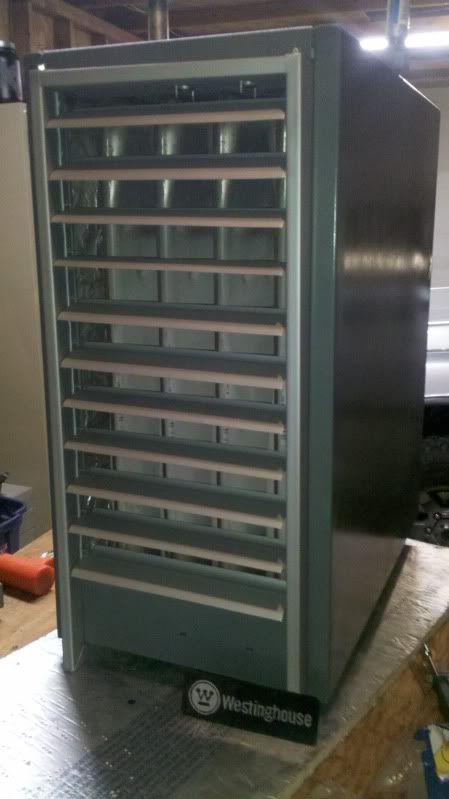
I purchased a older Westinghouse heater 64,000Btu heater off Craiglist a while back.

See here..
http://www.garagejournal.com/forum/showthread.php?t=149832

Well now I've got it all cleaned up and almost ready to hang.
2012-09-21_19-27-21_88_zps8f6617dc.jpg


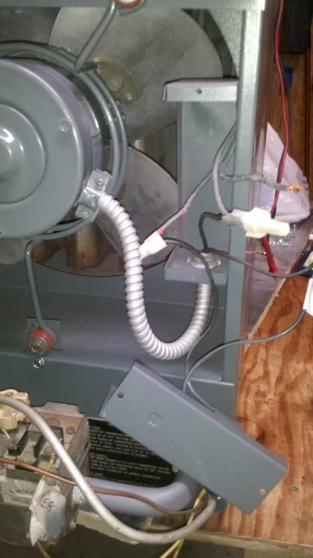
The only issue is when I disassembled the heater to repaint I marked most of the wires but left out the location of one of the main power in wires. I have scoured the internet for days and have never seen anything regarding wiring for these older Westinghouse type heaters. I've attempted to browse the wiring diagrams for Reznor and Dayton heaters but they seem to differ quite a bit or have no actual diagram. I really just want to confirm to myself that it's correct before I plug it in and fry everything. I'm a diesel mechanic with a extensive electrical background in DC circuits not AC so much.

The heater is entirely basic by design. Its old school no electronic pilot no solid state circuit boards. It has a 24v transformer for the gas regulator, two thermal switches in the upper hood, and an electric fan. That's it yet since I have no direction to follow I can't be sure I have it interconnected correctly.

Here is how I currently have it setup...
heatercrap_zpsd13c4772.jpg


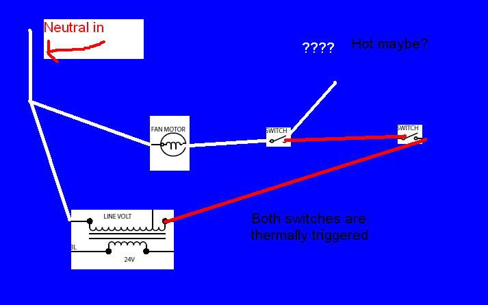
Switches. The black wire is the one I might think may be the hot wire.
2012-09-21_19-47-25_568_zps26f19993.jpg


The wires that run off the right side of the picture are the white neutral wires.
2012-09-21_20-12-33_577_zps78b7d4e5.jpg


Here is a name plate if anyone can help assist in finding a manual.
2012-09-21_20-17-40_739_zpsc93c7b98.jpg


Thanks
 
To avoid these ads, REGISTER NOW!
OP
M

mnster

Well-known member
Joined
Feb 17, 2011
Messages
75
Location
Rockford, IL
Well I plugged it in anyway and nothing happened. I can hear the transformer bmmmmmm vibrating. So I know it was getting power. I figured the switches overhead were not warm enough thereby not engaging the fan. So I took out my propane torch and heated airspace about 3 inches from the switch (not pointed at the switch) and nothing switched.

I'm guessing the switches are put in place to thermally actuate the fan is that correct? I take it the heater builds heat then when the switches are hot enough the fan turns on and blows heat out.

Jumpering over the switch and presto we have fan movement.
2012-09-21_21-51-37_709_zpsc46d0dfd.jpg
 
Last edited:

mrobins297aaa

Well-known member
Joined
Sep 20, 2010
Messages
3,283
Location
south east michigan
I would think one of those switches is the safety...........which ever one is closed at room temperature is the safety, the other one could be use to start the fan or it could be another safety............its hard to see is there any other controls?
I think it will work the way you have it wired, if they are using that thermo disk to start the fan it should be in the open position. In your drawing the switch on the right should be the safety so if it over heats it will open and cut power to the transformer and the fan will continue to run to cool things down.
 
Last edited:

mrobins297aaa

Well-known member
Joined
Sep 20, 2010
Messages
3,283
Location
south east michigan
Yeah i wouldn't use a propane torch to check them but maybe a heat gun would work.
my guess is the safety will open up somewhere around 200 deg and the other switch to start the fan my closed around 110 deg.

i would just get the thing in place and get the gas on and then see what happens, it may work just fine..............and if it don't you don't have anything major wrong there that you can't get at and change later.........what ever you do don't run it without that safety.
 

Ironhorse

Well-known member
Joined
Sep 17, 2012
Messages
800
From your wiring chart...why would you have two switches in line to switch one device? My guess is you have one thermo switch for the fan motor...and one switch for the numatic gas valve. Are both switches 120volt? or is one 24volt off the thremostat transformer? check the rating on the valve and see if it is 24volt or 120 volt...if 120volt...I will guess you know what to do. Just a thought.
 
To avoid these ads, REGISTER NOW!

mrobins297aaa

Well-known member
Joined
Sep 20, 2010
Messages
3,283
Location
south east michigan
From your wiring chart...why would you have two switches in line to switch one device? My guess is you have one thermo switch for the fan motor...and one switch for the numatic gas valve. Are both switches 120volt? or is one 24volt off the thremostat transformer? check the rating on the valve and see if it is 24volt or 120 volt...if 120volt...I will guess you know what to do. Just a thought.

That gas valve looks like the standard 24 volt valve to me and besides there would no need for the transformer if the gas valve was 120volt, on that system the only job of that transformer is to supply 24 volt power to the gas valve via of the thermostat.

the thermo switch that controls the gas valve doesn't have to be 24 volt to control it it just needs to break the 120 volt power to the transformer.
 
Last edited:
OP
M

mnster

Well-known member
Joined
Feb 17, 2011
Messages
75
Location
Rockford, IL
I would think one of those switches is the safety...........which ever one is closed at room temperature is the safety, the other one could be use to start the fan or it could be another safety............its hard to see is there any other controls?
I think it will work the way you have it wired, if they are using that thermo disk to start the fan it should be in the open position. In your drawing the switch on the right should be the safety so if it over heats it will open and cut power to the transformer and the fan will continue to run to cool things down.


You are correct the switch next to the fan switch is a normally closed safety. I pointed the torch more in the direction of the switch and bam fan engaged. I tested the safety switch which clicked off as well. Thanks for the explanation. I had realized it was normally closed but wasn't completely sure why and if it was broke or something. Appears to function perfectly.


Yeah i wouldn't use a propane torch to check them but maybe a heat gun would work.
my guess is the safety will open up somewhere around 200 deg and the other switch to start the fan my closed around 110 deg.

i would just get the thing in place and get the gas on and then see what happens, it may work just fine..............and if it don't you don't have anything major wrong there that you can't get at and change later.........what ever you do don't run it without that safety.

Yeah I wished my harbor freight heat gun was still working it spewed sparks a few months ago and that was it. Again thanks for the temperature ball park. Made it easier to guess if they were functioning at the proper temps.

Yeah I just wanted to make sure it was functioning some what on the bench before hanging it over head. working on the bench sure beats the cramped wall on a ladder. But, that is the plan now that it seems safe and secure wire wise. This heater has been converted to propane and I need to convert it back to natural gas.

That gas valve looks like the standard 24 volt valve to me and besides there would no need for the transformer if the gas valve was 120volt, on that system the only job of that transformer is to supply 24 volt power to the gas valve via of the thermostat.

the thermo switch that controls the gas valve doesn't have to be 24 volt to control it it just needs to break the 120 volt power to the transformer.

Yes a standard UNitrol 24v gas valve. Which I now need to find a wiring diagram or explanation of how to hook the transformer, thermostat, together. Though since I'm converting to natural gas I might need a new gas valve? Or might they make a part that converts it? I might just have a pro step in after me and adjust as needed I have no idea what is still original with this heater. If the previous owner switched the gas valve, pilot light, and orfices or not. It makes it hard to know what it came with. Still though I only paid $50 for this heater so I guess I have spare change to fix it as need be.
 

mrobins297aaa

Well-known member
Joined
Sep 20, 2010
Messages
3,283
Location
south east michigan
the 24 v wiring would be as follows: one wire from the transformer to the R terminal of the T stat , one wire from the W terminal on the T stat to one terminal of the gas valve, one wire from the other terminal on the gas valve to the other side of the transformer.

to convert to propane you need to change the orfices in the burners and the pilot light.
and the pressure spring in the gas valve.

I never seen anybody make a gas valve for propane they usually just give you the natural gas valve and the kit to convert it.

check around you may still be able to get the kit, use the numbers on the valve not the unit numbers. The kit is really quite simple to install (comes with instructions) but unless you have a manometer to set the gas pressure for propane you will need to get someone to help you.

also unless you have a digital stat you'll have to set the heat antisapator in the thermostat. if its not set correct the system can short cycle on and off. Remove the cover to the stat and look for a dial or pointer, it will usually say "longer or shorter" somewhere on there refering to the cycle lengths. What you are setting is the current flow thru the circuit, look on the gas valve for a ink stamp like ".2 amps or something similar. That is the setting you use on the the T stat. if there's nothing there set it at .2 amps I think that would be close for that system. You could also actually measure it.
 
OP
M

mnster

Well-known member
Joined
Feb 17, 2011
Messages
75
Location
Rockford, IL
Thanks I've since ordered the natural gas regulator attachment for this gas valve. The orifice's appear to be #44 which when I look at a chart appear to be the correct size for the output on natural gas. Might pick up a drill bit to be sure they were not drilled. Then I need to inspect the pilot for size. Get a gauge if need be to check the water column. But, I really need to figure out the codes regarding running the stove pipe. I'd like to run it though the roof. Is there a link somewhere that has the national standards of how it can be run or is it a local thing? If it is local where might I find the codes? I'd like to start planning where to hang it but every time I find myself scratching my head about how the pipe needs to be run. I know the 10ftx 3ft min rule of off the height of the pitch of the roof. But, must it be a certain distance from the edge of the house? Thanks again for your help.
 
To avoid these ads, REGISTER NOW!
Top Bottom