Motorman55
Well-known member
Looking to replace these older rotary dimmer switches with new style slide types.
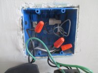
Curios as to how these were wired. Not sure if an electrician did it or the PO of the house.
1st Each switch controls a separate ceiling light fixture in the kitchen.
2nd Both switches are on the same breaker.
Obviously they both work, but why is it wired this way and should the white wire on the right that's cut off have a wire nut on it.
Also I would think that both switches need to be grounded to the larger grounding wire.
What would the wiring schematic look like?
Thanks for any info.
Curios as to how these were wired. Not sure if an electrician did it or the PO of the house.
1st Each switch controls a separate ceiling light fixture in the kitchen.
2nd Both switches are on the same breaker.
Obviously they both work, but why is it wired this way and should the white wire on the right that's cut off have a wire nut on it.
Also I would think that both switches need to be grounded to the larger grounding wire.
What would the wiring schematic look like?
Thanks for any info.