To avoid these ads, REGISTER NOW!

Need Some Electronic Repair Help

KDoug

Well-known member
Joined
Feb 26, 2018
Messages
388
Location
Southeast Texas
Hi,

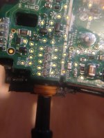
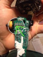
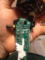
I'm trying to repair a Dewalt Oscillating tool, and to do that I had to take the circuit board out. I accidentally chipped one of the components trying to get the board out. I've been watching several electronic videos on how to desolder and replace SMD components like this and I've practiced on a scrap circuit board from one of my other power tools. So I've got two questions:

What is this part? I has the number 102 on it.

Where can I get an equivalent replacement?

Sorry if the pictures aren't that great, it was hard to get the camera to focus.
 

Attachments

  • IMG_3201.jpg
    IMG_3201.jpg
    91.1 KB · Views: 189
To avoid these ads, REGISTER NOW!

captaindiode

Well-known member
Joined
Jul 8, 2013
Messages
371
Location
NC
It looks like an SMD resistor pack. 102 would indicate 1,000 ohms. If you have an digital meter, set it on ohms and measure across the opposing pins. The are four 1,000 (or 1k) ohms resistors in it. I would measure it before I tried replacing and see if you really damaged it.

1 is the first number in the value
0 is the second number in the value
2 means multiply by 100 or add two zeros
 

MBfreak

MEMBER EMERITUS
Joined
Dec 10, 2010
Messages
2,301
Location
Linkoping , Sweden
Pic not clear enough for me to really see.
Like captaindiode says, it is probably a SMD 1000 Ohm resistor.
I THINK it is a single resistor, I have not seen SMD´s in " packs " they were quite common on pinconnected resistor packs.
If it is a single resistor, get two solder irons with fine tips and melt both pads while lifting the part.
Clean the pads with solder wick. Hold the new part in correct position and resolder one pad at a time using a very small amount of tin.

Ola
 
OP
K

KDoug

Well-known member
Joined
Feb 26, 2018
Messages
388
Location
Southeast Texas
It looks like an SMD resistor pack. 102 would indicate 1,000 ohms. If you have an digital meter, set it on ohms and measure across the opposing pins. The are four 1,000 (or 1k) ohms resistors in it. I would measure it before I tried replacing and see if you really damaged it.

1 is the first number in the value
0 is the second number in the value
2 means multiply by 100 or add two zeros

Thanks, that was very helpful. I read something briefly on the resistor coding but wasn't sure if it applied to my case because I was unsure if it was a resistor or not.

I think it works, I was just wanting to see if I could replace it in case I did any damage to it. I bought all the stuff to do it: ChipQuik and a fine point soldering iron tip. The ChipQuik works good, I tried removing some small resistors on a scrap board I had.
 

Miss the Pontiacs

Well-known member
Joined
Nov 7, 2016
Messages
16,446
Location
Saskatchewan Canada
It looks like an SMD resistor pack. 102 would indicate 1,000 ohms. If you have an digital meter, set it on ohms and measure across the opposing pins. The are four 1,000 (or 1k) ohms resistors in it. I would measure it before I tried replacing and see if you really damaged it.

1 is the first number in the value
0 is the second number in the value
2 means multiply by 100 or add two zeros

:bowdown: Wow that is certainly easier than what I remember. Is there much use for the old school method that I had to learn? In the end we didn’t use it much. We would just isolate the problem replace the card, mark the repair tag and it became someone else’s Edit

Further information: List of electronic color code mnemonics
A useful mnemonic matches the first letter of the color code, in numeric order. Here are two that includes tolerance codes gold, silver, and none:

Bad beer rots our young guts but vodka goes well – get some now.[13]
Black Brown ROY of Great Britain had a Very Good Wife who wore Gold and Silver Necklace.
The colors are sorted in the order of the visible light spectrum: red (2), orange (3), yellow (4), green (5), blue (6), violet (7). Black (0) has no energy, brown (1) has a little more, white (9) has everything and grey (8) is like white, but less intense.[14]
 

Attachments

  • B3EC77CA-52B8-442A-8AAC-CD6194A0E16F.jpeg
    B3EC77CA-52B8-442A-8AAC-CD6194A0E16F.jpeg
    37 KB · Views: 28
OP
K

KDoug

Well-known member
Joined
Feb 26, 2018
Messages
388
Location
Southeast Texas

pgray007

Well-known member
Joined
Jul 25, 2007
Messages
573
Location
Charlotte, NC area
I've wondered that too, their shipping must be subsidized by the Gov't


Incidentally, you’re right. There’s a policy for reduced rate postage from “economically disadvantaged” countries from a couple decades ago. The idea being that you’d give small companies in places like Africa access to US consumers so they could grow small businesses, improve their economies, etc.

Like many good ideas, China is pretty far from the economic backwater it was when the policy was enacted, so now they can ship to the US through the postal system way cheaper than I can ship the same package to the next town over.


Sent from my iPhone using Tapatalk
 
To avoid these ads, REGISTER NOW!

outdoorspace

Banned
Joined
Jan 28, 2014
Messages
356
Thanks, how would I know the spacing between the tabs? If I do a google search, what would be the proper nomenclature I should use?

Use a caliper and compare your measurements to the dimensions in the datasheet. By far the most common package for resistor arrays is 0.12" x 0.06".
 
OP
K

KDoug

Well-known member
Joined
Feb 26, 2018
Messages
388
Location
Southeast Texas
So I finally got around to measuring the resistance on the resistor and I'm consistently measuring .3 ohms. Does that even sound right or do I have my meter set incorrectly?
 

RPH

Well-known member
Joined
Dec 17, 2006
Messages
4,190
Location
Michigan Thumb
Is the device isolated when measuring? If not, then there is a good chance you’re measuring a parallel path through the circuit. Hardest thing I have with the new guys is to make sure their measuring what they think they are. Surface mount components come in sizes that are 605, 805, and a few others. Wrong size and it won’t fit the pads. Some are the size of ground pepper grains.
 

ransil

Well-known member
Joined
Jul 22, 2018
Messages
313
Location
pa
Size looks like a 0603 or 0805
Hard to tell in a picture
Small chip might not hurt it, if it is bad from chipping/ cracking it will read open.
.3 ohms something not reading right.
Its a resistor array so you need to check all 4 resistors, should be straight across.


Sent from my SM-G920V using Tapatalk
 
Last edited:
OP
K

KDoug

Well-known member
Joined
Feb 26, 2018
Messages
388
Location
Southeast Texas
Is the device isolated when measuring? If not, then there is a good chance you’re measuring a parallel path through the circuit. Hardest thing I have with the new guys is to make sure their measuring what they think they are. Surface mount components come in sizes that are 605, 805, and a few others. Wrong size and it won’t fit the pads. Some are the size of ground pepper grains.

If by isolated you mean it's been removed from the board, it hasn't been. CaptainDiode mentioned in a previous post above to measure the resistance while on the board. Don't know if that's right or wrong. There are 3 other resistors just like and they read .3 ohms as well. Unless I'm measuring the wrong pins. The 102 code says that it is supposed to be 1K ohms.
 
OP
K

KDoug

Well-known member
Joined
Feb 26, 2018
Messages
388
Location
Southeast Texas
Alright so from what I've gathered from the comments on here is that the resistor should be fine... still bugs me I don't know enough to find an equivalent replacement part.

Anyways, I've got one more part I need to find which was the initial problem. There is a connector on the board that is wired to the battery terminals (with 20 AWG) that burnt out. I thought about soldering the wires directly to the board, but the wire is too big in diameter to fit through the holes on the board. If someone could point me in the right direction with a similar part I'd very much appreciate it. I think it has a 2.5mm pin spacing. There is a lot of parts that come up on Google when I type in "wire to board connector", and I feel lost.

Attached are some pictures.
 

Attachments

  • IMG_3187.jpg
    IMG_3187.jpg
    64.1 KB · Views: 29
  • IMG_3178.jpg
    IMG_3178.jpg
    75.4 KB · Views: 28
OP
K

KDoug

Well-known member
Joined
Feb 26, 2018
Messages
388
Location
Southeast Texas
Since I haven't got a whole lot of replies to this thread, does anybody have a good electronics forum I can ask my questions?

Thanks
 

ozymandis

New member
Joined
Mar 1, 2017
Messages
4
There`s a Russian guy on here who does that kind of thing, send him a message he`s great, his blog`s a good long read. Im sure he would help you.
Find his garage thread I think its called "a small garage in Russia". He repairs allsorts of stuff this is right up his street, he also likes Americans.I cant remember his nickname on here it`s Viouk or Vlouk something like that, short for Vladimir.
 
OP
K

KDoug

Well-known member
Joined
Feb 26, 2018
Messages
388
Location
Southeast Texas
There`s a Russian guy on here who does that kind of thing, send him a message he`s great, his blog`s a good long read. Im sure he would help you.
Find his garage thread I think its called "a small garage in Russia". He repairs allsorts of stuff this is right up his street, he also likes Americans.I cant remember his nickname on here it`s Viouk or Vlouk something like that, short for Vladimir.

Thanks, pretty much am wrapping up this project at this point, but will keep that in mind for the future
 
To avoid these ads, REGISTER NOW!
Top Bottom