To avoid these ads, REGISTER NOW!

Need some motor wiring help

rslaback

Well-known member
Joined
Jul 24, 2010
Messages
4,086
Location
Westcentral Wisconsin
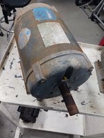
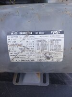
I picked up a pallet of used motors because I needed a specific one of them for my brake lathe. Before posting the extras up for sale I am verifying that they run.

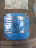
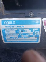
One of the motors is a Gould Century 6-350468-40 which is a 10HP motor on 200-230V single phase.

The wiring diagram shows me most of what I need. I have 4 winding motor leads that come out labeled 1,4, 5 and 7. The diagram appears to show that wire 7 goes to an external capacitor bank and the wire returning from that is called wire 8. L1 gets tied to 4 and 5. L2 gets tied to 1 and 8. However, it does not say what the additional two yellow 16awg wires are for. Can anyone provide some help with that? Is that for a missing overload or something? The plate for the peckerhead was missing so it is possible those went to a component on that cover.

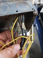
20250901_011841.jpg


17567083096367727991625325004478.jpg


17567083653071474948794651240847.jpg


17567084091605784443182329661299.jpg
 
Last edited:
To avoid these ads, REGISTER NOW!

mm08822

Well-known member
Joined
Jan 13, 2012
Messages
6,073
Location
NJ
Look up PTC motor thermal protection.

You won't need it connected initially to verify motor operation but eventually will need to ensure that feature works as part of your offering.
 

micromind

Well-known member
Joined
Sep 24, 2023
Messages
3,124
Location
Fernley, Nevada, about 30 miles east of Reno.
Most likely some sort of thermal protection.

As noted, they could be PTC or a Klixon or they could be winding heaters.

A PTC will usually read 50 - 100Ω.

A Klixon will read close to zero Ω.

Winding heaters are usually more than 100Ω

This motor most likely has a Klixon. If it does, it's a good idea to connect the yellow wires in series with the starter control circuit. This way you have double overload protection.
 

walta

Well-known member
Joined
Jan 13, 2017
Messages
2,313
Location
Dutzow Missouri
This motor is only really useable for driving fans that move air and the motor must be located in the air stream to provide cooling of the motor. It will have almost zero starting toque.

What else is on the pallet?
 

Attachments

  • 2025-09-01_11-06-46.gif
    2025-09-01_11-06-46.gif
    510.8 KB · Views: 3

Chuckster in NJ

Well-known member
Joined
Jan 26, 2010
Messages
2,334
Location
Hunterdon County NJ
This motor is only really useable for driving fans that move air and the motor must be located in the air stream to provide cooling of the motor. It will have almost zero starting toque.

What else is on the pallet?
TRUE! This motor was most likely used in a green house exhaust fan……. Note the minor corrosion on the outside of the motor.

BTW! The motor even says: HIGH EFFICIENCY CROP DRYER so it needs air pulled across it to lower heat.
 
OP
R

rslaback

Well-known member
Joined
Jul 24, 2010
Messages
4,086
Location
Westcentral Wisconsin
TRUE! This motor was most likely used in a green house exhaust fan……. Note the minor corrosion on the outside of the motor.

BTW! The motor even says: HIGH EFFICIENCY CROP DRYER so it needs air pulled across it to lower heat.
I assume in my location that it was actually used in a corn dryer. Which is fine because guys around here sometimes need replacement motors for their corn dryers.
 

fitter30

Well-known member
Joined
Jun 23, 2019
Messages
3,000
Location
Peace Valley,mo
4 & 5 - L1
1 - L 2
7 goes to one side of the capacitor/ s
3 connects to other side of capacitor/s & L2 ( 100 mfd or uF X 370 vac cap)
Two yellows go to a thermostat
Couldn't find a diagram other than what's on motor. K221 is the catalog # located second from the bottom of motor tag left side. K221 was replaced by K221 R2 and uses a thermostat . With capacitors in circuit full time use run type caps not starting.
 
OP
R

rslaback

Well-known member
Joined
Jul 24, 2010
Messages
4,086
Location
Westcentral Wisconsin
4 & 5 - L1
1 - L 2
7 goes to one side of the capacitor/ s
3 connects to other side of capacitor/s & L2 ( 100 mfd or uF X 370 vac cap)
Two yellows go to a thermostat
Couldn't find a diagram other than what's on motor. K221 is the catalog # located second from the bottom of motor tag left side. K221 was replaced by K221 R2 and uses a thermostat . With capacitors in circuit full time use run type caps not starting.
I think the 3 is actually a mangled 8. The rotation diagram shows 1, 4, 5 and 8.
 
To avoid these ads, REGISTER NOW!

nadogail

Well-known member
Joined
Jan 23, 2009
Messages
32,081
Location
Coronado, CA
I used to grab the used capacitors from when I changed out the ballasts during repairs to the shop lighting system. Those motor capacitors don't need to be exact, just "sort of close", 10% is almost exact.
 

dscheidt

Well-known member
Joined
Apr 26, 2017
Messages
2,916
It covers the peak voltage value of the ac sine wave. A higher voltage rating usually provides a longer cap life. The only drawback that I know is, it means a larger volume for the same microfarad rating.
Caps have gotten smaller, so it’s often easy to fit a higher voltage rated capacitor in the same space.
 
To avoid these ads, REGISTER NOW!
Top Bottom